

prEN IEC 62052-11:2026
(Main)Electricity metering equipment - General requirements, tests and test conditions - Part 11: Metering equipment
- Status
- Not Published
- Publication Date
- 14-Nov-2027
- Technical Committee
- CLC/TC 13 - Equipment for electrical energy measurement and load control
- Current Stage
- 4060 - Enquiry results established and sent to TC, SR, BTTF - Enquiry
- Start Date
- 28-Aug-2026
- Completion Date
- 28-Aug-2026

prEN IEC 62052-11:2026 is a CLC draft standard for electricity metering equipment. It specifies general requirements, tests and test conditions for AC and DC electricity meters, including construction, marking, metrological performance, climatic endurance and immunity to external influences. It is intended for manufacturers, test laboratories, conformity assessors and buyers who need to judge whether a meter design and test program fit the general requirements for metering equipment.
What does prEN IEC 62052-11:2026 specify?
prEN IEC 62052-11:2026 specifies the general requirements and associated type tests for electricity meters. The scope covers meters for electrical networks with nominal voltage up to 1 000 V AC or 1 500 V DC, and it includes meters with integrated displays, detached displays, or no display.
The document is organized into clauses for scope, normative references, terms and definitions, nominal electrical values, construction requirements and tests, marking and documentation, metrological performance, climatic requirements, external influence quantities and disturbances, and type test reporting. The annexes add detailed test outputs, symbol examples, EMC arrangements, special test circuits, guidance for multi-branch meters, guidance for transducer-operated meters, and reference formulas.
Meters with external transducers may be tested in two ways:
- as directly connected meters, when the meter and its transducers are tested together
- as transducer-operated meters, when the meter is tested without the transducers
Annex overview
| Annex | What it covers |
|---|---|
| Annex A | Optical test output |
| Annex B | Class A, B and C electrical pulse outputs and inputs |
| Annex D | Meter symbols and markings |
| Annex E | Meter ports |
| Annex F | Test set-up for EMC tests |
| Annex G | Test circuit diagrams for harmonics and interharmonics |
| Annex H | Short-time overcurrent test waveform |
| Annex I | Fast load current variation test |
| Annex J | Electromagnet for external magnetic field testing |
| Annex K | Earth fault test circuit |
| Annex L | Meter current signal range |
| Annex M | Application to Multi-Branch Circuit Energy Meters |
| Annex N | Testing of transducer-operated meters |
| Annex R | Reference definitions and formulas for voltage, current, power and energy |
What are the key requirements of prEN IEC 62052-11:2026?
prEN IEC 62052-11:2026 combines construction, metrological, climatic and EMC requirements into one general framework for meter type testing. In practice, that means a meter has to be designed, marked and tested as a complete product, not just as a measuring element.
Construction, enclosure and interfaces
Clause 5 requires the meter to meet the safety requirements of IEC 62052-31:2024. It also requires corrosion protection for parts exposed in normal use, a meter case that keeps working after non-permanent deformation, and a cover that cannot be removed without a tool. For meters installed in a matching socket, rack or with a detached display, the tests are performed in that installation arrangement.
Clause 5 also covers windows, terminals, sealing provisions, measured-value display, storage of measured values, pulse outputs, pulse inputs and auxiliary power supply. For a user, this means the complete mechanical and interface design is part of conformity, including how readings are viewed, how seals are applied and how external signals are exchanged.
A notable practical requirement is that measured values must remain stored in non-volatile memory for at least 12 months after all external power is disconnected, and must be available again when power returns. That matters for billing continuity and for later verification after outages.
Marking and documentation
Clause 6 requires the meter to carry the markings needed by local regulations and the document set described in Table 8. The marking includes identification information, electrical ratings, accuracy class, meter constants, operating temperature range and, where relevant, transformer or transducer ratio and auxiliary supply data.
The document also requires a connection diagram or a reference to one, with phase sequence shown for polyphase meters. This matters because installers need to connect the meter correctly, and test labs need the same information to reproduce the declared configuration.
Metrological performance
Clause 7 sets the general conditions for accuracy testing. The meter is tested in its case with the cover in place, at thermal stability, with the specified phase sequence and balanced polyphase conditions where applicable. Accuracy can be verified either by a meter test method or by reading the energy registers through communications ports.
Clause 7 also requires uncertainty control in the test laboratory. If the expanded uncertainty is within the stated relationship to the accuracy limit, the measured error can be compared directly with the class limit; otherwise the acceptance limit is reduced by the uncertainty. In practice, this tells the laboratory how to judge borderline results.
The clause also covers meter constant verification, initial start-up time, no-load condition, repeatability, error variation with current, error shift due to influence quantities, and time-keeping accuracy for clocks needed by the meter’s primary functions. The start-up time is declared by the manufacturer, and the document notes a typical upper bound of 10 s except for certain multi-function meters.
Climatic performance and durability
Clause 8 requires meters to work and be stored or transported under the climatic conditions defined for indoor or outdoor use. It covers dry heat, cold, damp heat cyclic exposure and solar radiation. The display may have its own operating range, but it should recover and function correctly once conditions return to normal.
The durability requirement points to metrological stability testing in IEC CD 62059-32-1:2025. For a buyer or quality manager, that means long-term drift is treated as part of the design assessment, not as an afterthought.
External influences and EMC
Clause 9 covers the effects of external influence quantities and disturbances, including electromagnetic compatibility. The meter, detached display and transducers are tested in their normal working position, with representative accessories and cable layouts.
The acceptance criteria focus on primary functions:
- energy registration
- display operation
- operation of supply control switches and load control switches
Temporary degradation is allowed only within the defined limits. In particular, the meter must not lose the ability to restore its functions after the disturbance is removed, and software reset is not acceptable as a normal response. For disturbances that cause more severe effects, the energy register change is limited by the critical change value.
Clause 9 also includes tests for voltage dips and interruptions, DC ripple, electrostatic discharge, radiated RF immunity, conducted RF immunity, surge, ring wave, damped oscillatory wave, external static magnetic fields, power frequency magnetic fields, harmonics, frequency variation, reversed phase sequence, auxiliary voltage variation, short-time overcurrents, self-heating, fast load current variation and earth fault.
Type test reporting
Clause 10 requires a type test to be documented in a report that identifies the tested meter type, the configurations covered, the laboratory, the test sample identification and firmware details, the applied test methods, the results and the pass/fail rationale. This is what makes the document usable for certification, technical file preparation and repeatable conformity assessment.
What terms does prEN IEC 62052-11:2026 define?
- Meter - An instrument in which currents and voltages act on solid-state elements to produce an output proportional to the energy to be measured.
- Watt-hour meter / active energy meter - A meter intended to measure active energy by integrating active power over time.
- Multi-function meter - A meter that combines energy measurement with other functions such as demand indication, communication, control or power quality functions.
- Detached display (DD) - A display in its own enclosure, separate from the meter case, powered by the meter and intended only for designated meter types.
- Current signal - The measurand at the meter’s current circuit terminals, understood differently for directly connected, transformer-operated and transducer-operated meters.
- Influence quantity - A long-duration quantity that is not being measured but can affect metrological performance.
- Disturbance - A short-duration quantity that may affect metrological performance.
- Type test - A series of tests carried out on one meter or a small number of identical meters to check compliance with the relevant requirements.
Who uses prEN IEC 62052-11:2026?
Manufacturers use prEN IEC 62052-11:2026 when designing meter cases, displays, terminals, pulse interfaces, auxiliary supplies and markings, and when planning type testing. Test laboratories use it to set up verification, EMC and environmental tests, and to write reproducible test reports.
Utilities, metering specialists and buyers use it to compare meter designs on a common technical basis. It is also relevant to installers and integrators working with meter sockets, meter racks, detached displays, communication modules and control functions, because the standard ties compliance to the intended installation arrangement.
Quality managers and conformity assessment teams use it to check whether a meter family has been tested in representative configurations and whether the declared documentation matches the actual product design.
What changed in prEN IEC 62052-11:2026 from the previous edition?
prEN IEC 62052-11:2026 supersedes 13/1947/CD and 13/1994/CC.
Which standards are used with prEN IEC 62052-11:2026?
- IEC 62052-31:2024 - provides safety requirements, construction safety for detached displays, and several marking and durability references.
- IEC 62053 series - provides the accuracy-class-specific requirements that complement this general document.
- IEC 62057-1:2023 - provides meter test station and verification methods referenced for accuracy testing.
- IEC 62054-21:2004 - provides the time-keeping accuracy requirements for clocks used by meter primary functions.
- IEC 61000-4-11:2020 - provides the test method basis for voltage dips and short interruptions.
- IEC 61000-4-5:2014 - provides the surge test framework referenced for EMC immunity testing.
- IEC 61326-1:2020 - provides port definitions and EMC-related concepts used in the disturbance testing clauses.
- IEC 60068-2-1, -2-2, -2-5, -2-6, -2-27, -2-30, -2-47 and -2-64 - provide the environmental test methods for cold, dry heat, solar radiation, vibration, shock, damp heat and related mounting conditions.
- IEC 60721-1:1990, IEC 60721-3-3:2019 and IEC 60721-3-4:2019 - provide the environmental class framework used for indoor and outdoor operating conditions.
- IEC Guide 98-3:2008 and IEC Guide 98-4:2012 - provide the uncertainty estimation and decision-rule basis for acceptance of test results.
- IEC 60404-5:2015 and IEC 60404-8-1:2023 - provide material and measurement references for the magnetic field test arrangements.
- IEC 60038:2009 and IEC 60038:2009/AMD1:2021 - provide standard voltages used as the electrical basis.
- IEC 60381-1:1982 - provides the analogue signal reference used in the normative references list.
- NEMA C12.31G-TR-2024:2024 - provides the reference definitions and formulas reproduced in Annex R.
What does the prEN IEC 62052-11:2026 document contain?
The document contains detailed test methods for mechanical, electrical, climatic and EMC performance, along with the acceptance criteria used to judge results. It also contains marking tables, symbol examples, connection-diagram guidance and documentation requirements for meter cases, displays, transformer-operated meters and transducer-operated meters.
Several annexes provide practical test arrangements rather than only requirements. For example, Annex A gives the optical test output arrangement, Annexes B and C define electrical pulse outputs and inputs, Annex F shows EMC test set-ups, and Annex G gives circuit diagrams for harmonics and interharmonics testing.
The document also contains worked guidance for special cases. Annex M addresses Multi-Branch Circuit Energy Meters, Annex N addresses transducer-operated meters, Annex H explains the short-time overcurrent waveform basis, and Annex R gives the mathematical reference definitions for voltage, current, power and energy used for technical comparison and accuracy evaluation.
Relations
- Effective Date
- 18-Mar-2025
- Effective Date
- 12-Mar-2024
- Effective Date
- 12-Mar-2024
- Effective Date
- 12-Mar-2024
Get Certified
Connect with accredited certification bodies for this standard

BSMI (Bureau of Standards, Metrology and Inspection)
Taiwan's standards and inspection authority.
Sponsored listings
Frequently Asked Questions
prEN IEC 62052-11:2026 is a draft published by CLC. Its full title is "Electricity metering equipment - General requirements, tests and test conditions - Part 11: Metering equipment". This standard covers: Electricity metering equipment - General requirements, tests and test conditions - Part 11: Metering equipment
Electricity metering equipment - General requirements, tests and test conditions - Part 11: Metering equipment
prEN IEC 62052-11:2026 is classified under the following ICS (International Classification for Standards) categories: 17.220.20 - Measurement of electrical and magnetic quantities. The ICS classification helps identify the subject area and facilitates finding related standards.
prEN IEC 62052-11:2026 has the following relationships with other standards: It is inter standard links to EN IEC 62052-11:2021/prAC:2026, EN IEC 62052-11:2021, EN IEC 62052-11:2021/A12:2024, EN IEC 62052-11:2021/A11:2022. Understanding these relationships helps ensure you are using the most current and applicable version of the standard.
prEN IEC 62052-11:2026 is associated with the following European legislation: EU Directives/Regulations: 2014/30/EU, 2014/32/EU; Standardization Mandates: M/541, M/552. When a standard is cited in the Official Journal of the European Union, products manufactured in conformity with it benefit from a presumption of conformity with the essential requirements of the corresponding EU directive or regulation.
prEN IEC 62052-11:2026 is available in PDF format for immediate download after purchase. The document can be added to your cart and obtained through the secure checkout process. Digital delivery ensures instant access to the complete standard document.
Standards Content (Sample)
SLOVENSKI STANDARD
01-julij-2026
Oprema za merjenje električne energije - Splošne zahteve, preskusi in preskusni
pogoji - 11. del: Merilna oprema
Electricity metering equipment - General requirements, tests and test conditions - Part
11: Metering equipment
Elektrizitätszähler - Allgemeine Anforderungen, Prüfungen und Prüfbedingungen - Teil
11: Messeinrichtungen
équipement de comptage de l'électricité - Exigences générales, essais et conditions
d'essai - Partie 11: équipement de comptage
Ta slovenski standard je istoveten z: prEN IEC 62052-11:2026
ICS:
17.220.20 Merjenje električnih in Measurement of electrical
magnetnih veličin and magnetic quantities
91.140.50 Sistemi za oskrbo z elektriko Electricity supply systems
2003-01.Slovenski inštitut za standardizacijo. Razmnoževanje celote ali delov tega standarda ni dovoljeno.
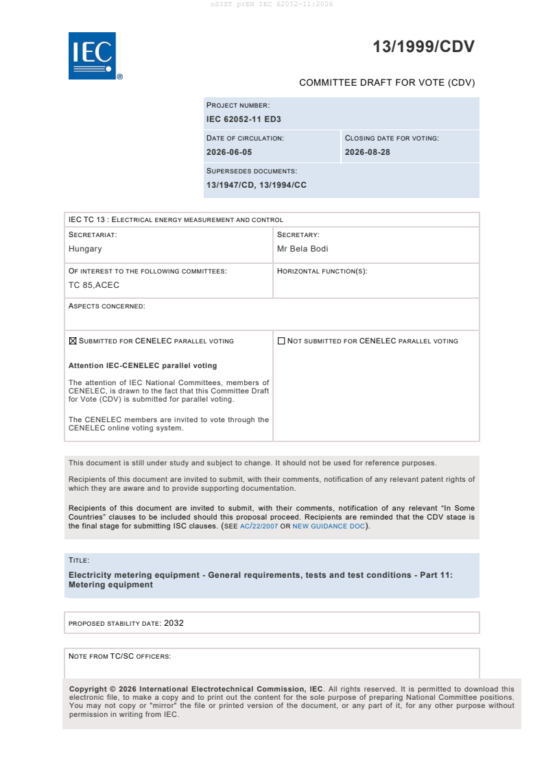
13/1999/CDV
COMMITTEE DRAFT FOR VOTE (CDV)
PROJECT NUMBER:
IEC 62052-11 ED3
DATE OF CIRCULATION: CLOSING DATE FOR VOTING:
2026-06-05 2026-08-28
SUPERSEDES DOCUMENTS:
13/1947/CD, 13/1994/CC
IEC TC 13 : ELECTRICAL ENERGY MEASUREMENT AND CONTROL
SECRETARIAT: SECRETARY:
Hungary Mr Bela Bodi
OF INTEREST TO THE FOLLOWING COMMITTEES: HORIZONTAL FUNCTION(S):
TC 85,ACEC
ASPECTS CONCERNED:
SUBMITTED FOR CENELEC PARALLEL VOTING NOT SUBMITTED FOR CENELEC PARALLEL VOTING
Attention IEC-CENELEC parallel voting
The attention of IEC National Committees, members of
CENELEC, is drawn to the fact that this Committee Draft
for Vote (CDV) is submitted for parallel voting.
The CENELEC members are invited to vote through the
CENELEC online voting system.
This document is still under study and subject to change. It should not be used for reference purposes.
Recipients of this document are invited to submit, with their comments, notification of any relevant patent rights of
which they are aware and to provide supporting documentation.
Recipients of this document are invited to submit, with their comments, notification of any relevant “In Some
Countries” clauses to be included should this proposal proceed. Recipients are reminded that the CDV stage is
the final stage for submitting ISC clauses. (SEE AC/22/2007 OR NEW GUIDANCE DOC).
TITLE:
Electricity metering equipment - General requirements, tests and test conditions - Part 11:
Metering equipment
PROPOSED STABILITY DATE: 2032
NOTE FROM TC/SC OFFICERS:
electronic file, to make a copy and to print out the content for the sole purpose of preparing National Committee positions.
You may not copy or "mirror" the file or printed version of the document, or any part of it, for any other purpose without
permission in writing from IEC.
Link to Committee Draft for Vote (CDV) online document:
Click here
How to access
This link leads you to the Online Standards Development (OSD) platform for National Mirror
Committee’s (NMC) comments. The project draft may be found further down this document.
Resource materials
We recommend NCs to review the available materials to better understand the member commenting
on the OSD platform. This includes the:
• OSD NC roles overview
• How to add and submit comments to the IEC
Contact
Should you require any assistance, please contact the IEC IT Helpdesk.
IEC CDV 62052-11 © IEC 2026
CONTENTS
CONTENTS . 1
FOREWORD . 8
INTRODUCTION . 11
1 Scope . 13
2 Normative references . 14
3 Terms and definitions . 17
3.1 General definitions . 18
3.2 Definitions related to the functional elements . 23
3.3 Definitions of meter ports . 27
3.4 Definitions of mechanical elements . 29
3.5 Definitions related to measurements . 31
3.6 Definitions related to external influences . 35
3.7 Definition of tests . 38
3.8 Definitions related to meter marking and symbols . 38
4 Nominal electrical values . 40
4.1 Voltages . 40
4.1.1 Nominal voltages signals . 40
4.1.2 Voltage signal ranges . 41
4.2 Currents . 41
4.2.1 Nominal current signals . 41
4.2.2 Starting current signal . 42
4.2.3 Minimum current signal . 42
4.2.4 Transitional current signal . 42
4.2.5 Maximum current signal . 42
4.2.6 Current signal ranges . 43
4.3 Frequencies . 43
4.3.1 Nominal frequencies . 43
4.3.2 Frequency ranges . 43
4.4 Power consumption. 43
5 Construction requirements and tests. 44
5.1 General . 44
5.2 Mechanical tests . 45
5.2.1 Acceptance criteria . 45
5.2.2 Shock test . 45
5.2.3 Vibration test . 45
5.3 Window . 46
5.4 Terminals - Terminal block(s) - Protective conductor terminal . 46
5.5 Sealing provisions . 46
5.5.1 General . 46
5.5.2 Sealing of meter case . 46
5.5.3 Sealing of meter terminal covers. 46
5.5.4 Sealing of detached displays . 47
5.5.5 Sealing of meter configuration . 47
5.6 Display of measured values . 47
5.6.1 General . 47
5.6.2 Meters without displays . 48
IEC CDV 62052-11 © IEC 2026
5.6.3 Meters with displays . 48
5.7 Storage of measured values . 49
5.8 Pulse outputs . 49
5.8.1 General . 49
5.8.2 Optical test output . 49
5.8.3 Electrical pulse outputs . 50
5.8.4 Operation indicator . 51
5.9 Electrical pulse inputs . 51
5.9.1 General characteristics . 51
5.9.2 Functional tests of electrical pulse inputs. 51
5.10 Auxiliary power supply . 52
6 Meter marking and documentation . 52
6.1 Meter accuracy class marking . 52
6.2 Meter marking . 52
6.3 Connection diagrams and terminal marking . 57
6.4 Symbols . 57
6.4.1 General . 57
6.4.2 Symbols for the measuring elements . 57
6.4.3 Symbols for transformer-operated or transducer-operated meters . 58
6.4.4 Identification of the displayed information . 58
6.4.5 Marking of the measured quantity . 58
6.4.6 Symbols of principal units used for meters (see Table 9) . 59
6.4.7 Symbols for auxiliary devices. 59
6.4.8 Symbols for communication ports . 59
6.5 Documentation . 59
6.5.1 Installation manuals . 59
6.5.2 Instruction for use . 60
7 Metrological performance requirements and tests . 60
7.1 General test conditions . 60
7.2 Methods of accuracy verification . 62
7.3 Measurement uncertainty . 62
7.4 Meter constant . 63
7.5 Initial start-up time of the meter . 64
7.6 Test of no-load condition . 64
7.7 Starting current signal test . 65
7.8 Repeatability test . 65
7.9 Limits of error due to variation of the current . 66
7.10 Limits of error shift due to influence quantities . 66
7.11 Time-keeping accuracy . 66
8 Climatic requirements and tests . 66
8.1 General . 66
8.2 Environmental conditions . 66
8.3 Tests of the effects of the climatic environments . 67
8.3.1 General test requirements . 67
8.3.2 Acceptance criteria . 67
8.3.3 Dry heat test . 67
8.3.4 Cold test . 68
8.3.5 Damp heat cyclic test . 68
8.3.6 Protection against solar radiation . 68
IEC CDV 62052-11 © IEC 2026
8.4 Durability . 69
9 The effects of external influence quantities and disturbances . 69
9.1 General . 69
9.2 Acceptance criteria . 71
9.3 Electromagnetic compatibility (EMC) . 72
9.3.1 General . 72
9.3.2 Voltage dips, short interruptions, and DC ripple . 74
9.3.3 Electrostatic discharge immunity test . 76
9.3.4 Radiated, radio-frequency, electromagnetic field immunity test - test
without current signal . 77
9.3.5 Radiated, radio-frequency, electromagnetic field immunity test - test
with current signal . 77
9.3.6 Electrical fast transient/burst immunity test . 78
9.3.7 Immunity to conducted disturbances, induced by radio-frequency fields . 78
9.3.8 Test for immunity to conducted, differential mode current disturbances . 79
9.3.9 Surge immunity test . 80
9.3.10 Ring wave immunity test . 83
9.3.11 Damped oscillatory wave immunity test . 84
9.3.12 External static magnetic fields . 85
9.3.13 Power frequency magnetic field immunity test . 86
9.3.14 Emission requirements . 86
9.4 Tests of immunity to other influence quantities . 87
9.4.1 General . 87
9.4.2 Harmonics in the current and voltage circuits . 87
9.4.3 Voltage signal variation . 88
9.4.4 Ambient temperature variation . 89
9.4.5 Interruption of phase voltage . 89
9.4.6 Frequency variation . 90
9.4.7 Reversed phase sequence. 90
9.4.8 Auxiliary voltage variation . 91
9.4.9 Operation of auxiliary devices . 91
9.4.10 Short-time overcurrents . 91
9.4.11 Self-heating . 92
9.4.12 Fast load current variations . 93
9.4.13 Earth fault . 93
10 Type test . 94
10.1 Test conditions . 94
10.2 Type test report . 94
Annex A (normative) Optical test output . 96
Annex B (normative) Class A, B and C electrical pulse outputs and inputs . 98
B.1 Electrical characteristics of pulse outputs and inputs . 98
B.1.1 Electrical characteristics of pulse outputs . 98
B.1.2 Electrical output pulse waveform . 98
B.1.3 Test of electrical pulse outputs . 99
B.1.4 Test of electrical pulse inputs . 99
B.2 Class C electronic pulse outputs . 100
B.2.1 Characteristics of class C electronic pulse outputs . 100
Annex C (normative) Electrical pulse output for special applications and long
distances according to IEC 60381-1:1982 . 102
IEC CDV 62052-11 © IEC 2026
C.1 Operating conditions and output pulse waveform . 102
C.2 Test of pulse output for special applications and long distances . 103
C.3 Test of pulse input for special applications and long distances . 103
Annex D (informative) Meter symbols and markings . 105
Annex E (informative) Meter ports . 115
Annex F (informative) Test set-up for EMC tests . 119
Annex G (normative) Test circuit diagrams for testing influence of harmonics and
interharmonics . 121
Annex H (informative) Short time overcurrent test waveform . 128
Annex I (informative) Fast load current variation test . 129
Annex J (normative) Electromagnet for testing the influence of externally produced
magnetic fields . 130
J.1 Permanent magnet and electromagnet for testing the influence of external
static magnetic field . 130
J.2 Electromagnet for testing the influence of external static magnetic field with
magneto-motive force of 1 000 At (ampere-turns) . 130
Annex K (normative) Test circuit diagram for the test of immunity to earth fault . 132
Annex L (informative) Meter current signal range . 133
Annex M (informative) Application to Multi-Branch Circuit Energy Meters . 134
M.1 Overview . 134
M.2 Definitions . 134
M.3 General . 134
M.4 Cross-channel influences . 135
M.5 Channel configuration and sealing for multi-branch meters . 135
M.6 Verification for multi-branch meters . 135
Annex N (informative) Testing of transducer-operated meters . 136
N.1 General . 136
N.2 Transducer-operated meters tested with external transducers, as directly
connected meters . 136
N.2.1 General . 136
N.2.2 Example test setup for testing transducer-operated meters as directly
connected meters . 137
N.3 Transducer-operated meters tested with reference transducers . 137
N.3.1 General . 137
N.3.2 Example test setup for testing transducer-operated meters with
reference transducers . 138
N.4 Other methods of testing of transducer-operated meters . 139
N.4.1 Example test setup for testing transducer-operated meters with
simulated transducer signals . 139
Annex O (informative) Application of this standard to meters with detached displays . 140
Annex P (informative) Geometric representation of active and reactive power . 141
Annex Q (informative) Immunity to conducted common mode disturbances in the
frequency range from d.c to 150 kHz . 145
Annex R (informative) Mathematical definitions of the measured quantities . 146
R.1 General . 146
R.2 Abbreviations . 146
R.3 Voltage and current . 148
R.3.1 Voltage and current in the continuous time domain . 148
R.3.2 Voltage and current in the discrete time domain . 149
IEC CDV 62052-11 © IEC 2026
R.3.3 Voltage and current in the frequency domain . 149
R.4 Active power . 150
R.4.1 Active power in the continuous time domain . 150
R.4.2 Active power in the discrete time domain . 150
R.4.3 Active power in the frequency domain. 151
R.5 Active energy . 151
R.5.1 Active energy in the continuous time domain . 151
R.5.2 Active energy in the discrete time domain . 151
R.5.3 Active energy in the frequency domain . 152
R.5.4 Active energy in polyphase system . 152
R.6 Reactive power . 152
R.6.1 Fundamental reactive power in the frequency domain . 152
R.7 Reactive energy . 152
R.7.1 Fundamental reactive energy in the frequency domain . 152
R.7.2 Reactive energy in polyphase systems . 152
Bibliography . 153
Figure A.1 – Test arrangement for the optical test output . 96
Figure A.2 – Waveform of the optical test output . 96
Figure B.1 – Physical interface of the electrical pulse output . 98
Figure B.2 – Electrical output pulse waveform. 98
Figure B.3 – Pulse output test set-up . 99
Figure B.4 – Pulse input test set-up . 99
Figure B.5 – Non-isolated pulse output schematic . 100
Figure B.6 – Isolated pulse output schematic . 100
Figure B.7 – Electronic pulse output waveform . 101
Figure C.1 – Output pulse waveform . 102
Figure C.2 – Pulse output test set-up . 103
Figure C.3 – Pulse input test set-up . 104
Figure D.1 – Cross-phase connection of a var-hour meter with two measuring elements
in three-phase three-wire circuits . 109
Figure E.1 – Example: ports of a directly connected meter . 115
Figure E.2 – Example: ports of a transformer-operated meter . 116
Figure E.3 – Example: ports of a transducer-operated meter when type-tested with
transducers as a directly connected meter . 117
Figure E.4 – Example: ports of a transducer-operated meter when type-tested without
transducers . 118
Figure F.1 – Test set-up for the electrical fast transient/burst immunity test for
transformer-operated meters: each port (Mains, CT, HLV, ELV) is tested separately by
adding the coupling device to the respective port . 119
Figure F.2 – Test set-up for the electrical fast transient/burst immunity test for directly
connected meters : each port (Mains, HLV, ELV) is tested separately by adding the
coupling device to the respective port . 120
Figure G.1 – Test circuit diagram (informative, test of influence of interharmonics and
odd harmonics) on directly connected meter , transformer-operated meter , or
transducer-operated meter (current transducer with current output) . 121
Figure G.2 – Test circuit diagram (informative, test of influence of interharmonics and
odd harmonics) on transducer-operated meter (current transducer with voltage output) . 122
IEC CDV 62052-11 © IEC 2026
Figure G.3 – Burst-fired (integral cycle control) current signal waveform . 122
Figure G.4 – Informative distribution of interharmonic content of burst-fired current
signal waveform (the Fourier analysis is not complete) . 123
Figure G.5 – Phase fired waveform (odd harmonics) - 90° fired current signal waveform . 123
Figure G.6 – Informative distribution of harmonic content of 90° phase fired current
signal waveform (the Fourier analysis is not complete) . 124
Figure G.7 – Phase fired waveform (odd harmonics) - 45° fired current signal waveform . 124
Figure G.8 – Phase fired waveform (odd harmonics) - 135° fired current signal
waveform . 125
Figure G.9 – Test circuit diagram (informative) for half-wave rectification (DC and even
harmonics) . 125
Figure G.10 – Half-wave rectified current signal waveform (DC and even harmonics) . 126
Figure G.11 – Informative distribution of harmonic content of half-wave rectified current
signal waveform (the Fourier analysis is not complete) . 127
Figure J.1 – Electromagnet for testing the influence of external static magnetic field
with magneto-motive force of 1 000 At (ampere-turns) . 131
Figure K.1 – Circuit to simulate earth fault condition in phase 1 . 132
Figure K.2 – Voltages at the meter under test . 132
Figure L.1 – Meter current signal range . 133
Figure N.1 – Example test setup for testing transducer-operated meters as directly
connected meters . 137
Figure N.2 – Test setup for testing transducer-operated meters with external reference
transducers . 138
Figure N.3 – Test setup for testing transducer-operated meters with simulated
transducer signals . 139
Figure P.1 – Energy flow by quadrant [SOURCE: NEMA C12.31G-TR-2024:2024 [14]] . 141
Figure P.2 – Historical representation of energy flow by quadrant [SOURCE: NEMA
C12.31G-TR-2024:2024 [14]] . 142
Figure P.3 – Historical geometric representation [SOURCE: IEC 62053-23:2003 [21] ] . 143
Figure P.4 – Historical alternative geometric representation [SOURCE: IEC 62053-
23:2003 [21] ] . 144
Table 1 – Examples of constant C for different instrument transformer ratios . 39
Table 2 – Preferred nominal values of voltage signals . 40
Table 3 – Voltage ranges . 41
Table 4 – Preferred nominal values of current signals . 41
Table 5 – Current signal ranges . 43
Table 6 – Frequency ranges . 43
Table 7 – Maximum power consumption . 44
Table 8 – Marking and documentation requirements . 53
Table 9 – Symbols of principal units used for meters . 59
Table 10 – Voltage and current balance . 60
Table 11 – Reference conditions . 61
Table 12 – Repeatability test points . 65
Table 13 – Environmental conditions . 66
Table 14 – Summary of the tests of immunity to influence quantities . 70
IEC CDV 62052-11 © IEC 2026
Table 15 – Summary of the tests of immunity to disturbances . 70
Table 16 – Acceptance criteria . 71
Table 17 – Tests of immunity to dips and short interruptions of AC supply voltage . 74
Table 18 – Tests of immunity to dips and short interruptions of DC supply voltage . 75
Table 19 – Surge and ring wave immunity test levels for the meter's mains ports,
current transformer ports and current transducer ports . 82
Table 20 – Evaluation of primary meter functions under influence of voltage signal
variation for directly connected, and transformer or transducer-operated meters . 89
Table 21 – Short-time overcurrent test . 92
Table A.1 – Operating conditions of the optical test output . 97
Table B.1 – Operating conditions of the electrical pulse outputs . 98
Table B.2 – Test of pulse output . 99
Table B.3 – Test of pulse input device . 100
Table B.4 – Operating conditions of electronic pulse outputs . 101
Table C.1 – Operating conditions of pulse output for special applications and long
distances . 102
Table C.2 – Test of pulse output device . 103
Table C.3 – Test of pulse input device . 104
Table D.1 – Examples of voltage marking according to network voltage . 105
Table D.2 – Symbols for measuring elements . 106
Table D.3 – Marking of the measured quantity (examples) . 109
Table D.4 – Inscriptions of the accuracy class and the meter constant (examples) . 110
Table D.5 – Symbols for transformer-operated meters and transducer-operated meters
(examples) . 110
Table D.6 – Tariff function symbols (examples) . 111
Table D.7 – Symbols for tariff function (examples) . 112
Table D.8 – Symbols for auxiliary devices (examples) . 112
Table D.9 – Symbols for communication ports (examples) . 113
Table M.1 – Cross-channel influence test conditions for Multi-Branch Circuit Energy
Meters . 135
IEC CDV 62052-11 © IEC 2026
INTERNATIONAL ELECTROTECHNICAL COMMISSION
____________
Electricity metering equipment - General requirements, tests and test
conditions -
Part 11: Metering equipment
FOREWORD
1) The International Electrotechnical Commission (IEC) is a worldwide organization for
standardization comprising all national electrotechnical committees (IEC National Committees).
The object of IEC is to promote international co-operation on all questions concerning
standardization in the electrical and electronic fields. To this end and in addition to other
activities, IEC publishes International Standards, Technical Specifications, Technical Reports,
Publicly Available Specifications (PAS) and Guides (hereafter referred to as "IEC
Publication(s)"). Their preparation is entrusted to technical committees; any IEC National
Committee interested in the subject dealt with may participate in this preparatory work.
International, governmental and non-governmental organizations liaising with the IEC also
participate in this preparation. IEC collaborates closely with the International Organization for
Standardization (ISO) in accordance with conditions determined by agreement between the two
organizations.
2) The formal decisions or agreements of IEC on technical matters express, as nearly as
possible, an international consensus of opinion on the relevant subjects since each technical
committee has representation from all interested IEC National Committees.
3) IEC Publications have the form of recommendations for international use and are accepted
by IEC National Committees in that sense. While all reasonable efforts are made to ensure that
the technical content of IEC Publications is accurate, IEC cannot be held responsible for the
way in which they are used or for any misinterpretation by any end user.
4) In order to promote international uniformity, IEC National Committees undertake to apply IEC
Publications transparently to the maximum extent possible in their national and regional
publications. Any divergence between any IEC Publication and the corresponding national or
regional publication shall be clearly indicated in the latter.
5) IEC itself does not provide any attestation of conformity. Independent certification bodies
provide conformity assessment services and, in some areas, access to IEC marks of conformity.
IEC is not responsible for any services carried out by independent certification bodies.
6) All users should ensure that they have the latest edition of this publication.
7) No liability shall attach to IEC or its directors, employees, servants or agents including
individual experts and members of its technical committees and IEC National Committees for
any personal injury, property damage or other damage of any nature whatsoever, whether direct
or indirect, or for costs (including legal fees) and expenses arising out of the publication, use
of, or reliance upon, this IEC Publication or any other IEC Publications.
8) Attention is drawn to the Normative references cited in this publication. Use of the referenced
publications is indispensable for the correct application of this publication.
9) IEC draws attention to the possibility that the implementation of this document may involve
the use of (a) patent(s). IEC takes no position concerning the evidence, validity or applicability
of any claimed patent rights in respect thereof. As of the date of publication of this document,
IEC [had/had not] received notice of (a) patent(s), which may be required to implement this
IEC CDV 62052-11 © IEC 2026
document. However, implementers are cautioned that this may not represent the latest
information, which may be obtained from the patent database available at https://patents.iec.ch.
IEC shall not be held responsible for identifying any or all such patent rights.
IEC 62052-11:2025 has been prepared by IEC technical committee 13: Electrical energy
measurement and control. It is an International Standard.
This third edition cancels and replaces the second edition published in 2020. This edition
constitutes a technical revision.
This edition includes the following significant technical changes with respect to the previous
edition:
a) Normative references have been updated,
b) Transducer-operated meters included in scope (tested without transducers)
c) Definitions of instrument transformers, current sensors, transducers, and transducer-
operated meters have been added,
d) Definition of accuracy class has been revised; definition of accuracy class index has been
removed,
e
...