

prEN IEC 62282-2-400:2026
(Main)Fuel cell technologies - Part 2-400: Fuel cell modules - Calculation of rated power and power density of a PEM stack and PEM module
- Status
- Not Published
- Publication Date
- 09-Jan-2028
- Technical Committee
- CLC/SR 105 - Fuel cell technologies
- Drafting Committee
- IEC/TC 105 - IEC_TC_105
- Current Stage
- 4020 - Enquiry circulated - Enquiry
- Start Date
- 31-Jul-2026
- Due Date
- 07-Jul-2023
- Completion Date
- 31-Jul-2026

prEN IEC 62282-2-400:2026 is a draft IEC standard prepared by IEC Technical Committee 105 and submitted for CENELEC parallel voting. It specifies how to calculate the rated power and power density of proton exchange membrane (PEM) fuel cell stacks and PEM modules, and how to verify stabilized operation at rated and maximum power. It is aimed at people who need a common basis for testing, comparing, or declaring stack and module performance.
What does prEN IEC 62282-2-400:2026 specify?
prEN IEC 62282-2-400:2026 specifies methods for calculating rated power and power density for PEM fuel cell stacks and PEM modules. It also sets the test preparation and stabilized-operation method used to verify that the stack or module can deliver the declared power.
The document applies to PEM fuel cells irrespective of application and PEM technology type, including high-temperature PEM fuel cells. It focuses on the stack and module in their standalone state before peripheral devices affect net power output. It excludes fuel cell road vehicle applications and the storage and delivery of fuel and oxidant to the module.
The document is organized into clauses on scope, normative references, terms and definitions, symbols, test preparation, stabilized operation, mass and volume calculation, and power density, plus one normative annex.
| Annex | What it covers |
|---|---|
| Annex A | Stabilized operation test methods, test bench setup, data processing, mean output power, efficiency, and output voltage fluctuation |
What are the key requirements of prEN IEC 62282-2-400:2026?
Test preparation and measurement control
Clause 5 requires a documented test plan before any performance test is run. The plan has to cover the test object and its composition, operating conditions, target uncertainty, measurement instruments, data acquisition, and acceptance criteria. In practice, this means the test lab must define the full measurement setup before starting, rather than trying to reconstruct it after the fact.
Clause 5 also requires hydrogen handling to follow ISO TR 15916 and calls for high-accuracy instrumentation and planned recording intervals. The practical point is that reported power and density values only have value if the measurement chain is controlled and traceable.
Environmental and operating conditions
Clause 5.2 sets minimum instrument accuracy expectations for voltage, current, temperature, time, flow rate, pressure, and humidity. Clause 5.3 then requires testing under defined laboratory conditions, with the stack or module installed and operated according to the manufacturer’s instructions.
For gas and coolant conditions, the document requires hydrogen grade D from ISO 14687:2025 and manufacturer-defined inlet and outlet conditions. Air composition, including key contaminants named in the document, is recorded in the test report as specified by the manufacturer. In practice, performance claims are tied to declared operating conditions, so test reports need to show what the stack or module actually saw.
Stabilized operation at rated and maximum power
Clause 6 requires a stabilized operation test to show that the fuel cell stack or fuel cell module can operate at rated power and maximum power. Annex A gives the method: operate at rated current and maximum current, keep the electrical load connected, and repeat the test run as agreed between the user and the manufacturer.
The mean output power at rated current and maximum current must meet or exceed the rated power and maximum power, respectively. The test also records efficiency and output voltage fluctuation. That matters because a claimed power figure is only useful if the product can hold it in steady operation, not just momentarily.
Mass and volume calculations
Clause 7 requires the composition of the compressed cell row assembly, fuel cell stack, and fuel cell module to be recorded in the test report. The dry mass of the stack or module is measured directly, while the compressed cell row assembly is an optional calculation based on the masses of the bipolar plates and MEAs with gas seals.
Volume is treated in a similar way. The document allows volume to be determined from geometry, with the compressed cell row assembly volume based on cell area and the distance between end plates. If the manufacturer provides a model, critical dimensions need verification. In practice, this keeps power density based on measured or checked boundaries rather than on optimistic assumptions.
Power density reporting
Clause 8 requires mass power density and volume power density to be calculated at rated power and at maximum power. The calculations are provided for the compressed cell row assembly, the fuel cell stack, and the fuel cell module.
This is the key comparison metric for buyers and integrators. It lets them compare products on a common basis such as W/kg and W/L, while keeping the same boundary definition across different designs.
What terms does prEN IEC 62282-2-400:2026 define?
- Compressed cell row assembly - the assembly of successive MEAs and bipolar plates, including gas seals, compressed in the fuel cell stack.
- Fuel cell stack - an assembly of cells, separators, cooling plates, manifolds, and a supporting structure that converts reactants to DC power, heat, and other reaction products.
- Fuel cell module - an assembly with one or more fuel cell stacks and additional components intended to be integrated into a power system or vehicle.
- Rated power - the maximum continuous electric power output that a fuel cell stack or fuel cell module is designed to achieve under normal operating conditions specified by the manufacturer.
- Maximum power - the highest electric power output that a fuel cell stack or fuel cell module can be operated at, as specified by the manufacturer.
- Mass power density - the ratio of rated power or maximum power to the dry mass of a compressed cell row assembly, fuel cell stack, or fuel cell module.
- Volume power density - the ratio of rated power or maximum power to the volume of a compressed cell row assembly, fuel cell stack, or fuel cell module.
Who uses prEN IEC 62282-2-400:2026?
Manufacturers of PEM stacks and PEM modules use this document to define how they calculate and report rated power and power density. Test laboratories use it to set up stabilized-operation tests, measure output, and process the results in a repeatable way.
System integrators and buyers use it when they need to compare products on the same performance basis. Quality, validation, and certification teams use it to check that test plans, measurements, and reported values are aligned with the same boundary conditions and calculation method. It is relevant across PEM fuel cell applications outside road vehicles.
What changed in prEN IEC 62282-2-400:2026 from the previous edition?
prEN IEC 62282-2-400:2026 supersedes 105/935/CD and 105/965A/CC.
Which standards are used with prEN IEC 62282-2-400:2026?
- ISO TR 15916 - provides the hydrogen safety guidance used for handling hydrogen during test preparation.
- ISO 14687:2025 - defines the hydrogen fuel quality requirement, including the grade used for testing.
- ISO 10303-42 - supports CAD-based geometric representation for determining cell area and volume.
- ISO 10360 (all parts) - supports acceptance and reverification tests for coordinate measuring machines used to verify dimensions.
- ISO 1183-1 - supports the immersion method mentioned for determining volume.
- IEC 62282-2-100:2020 - provides the fuel cell power system context referenced in the scope.
- IEC 62282-3-200:2015 - is cited for uncertainty-analysis guidance.
- ISO/IEC Guide 98 (all parts) - is cited as an alternative basis for measurement uncertainty analysis.
What does the prEN IEC 62282-2-400:2026 document contain?
The document contains symbols for power, mass, volume, efficiency, and output-voltage fluctuation in Table 1. It also contains the test preparation requirements in Clause 5, including laboratory conditions, operating conditions, and measurement accuracy expectations.
Annex A provides the stabilized-operation test methods. It includes the test bench arrangement, the agreed conditioning procedure, the rated-power and maximum-power test steps, and the data-processing formulas for mean output power, efficiency, and output voltage fluctuation.
The figures show the fuel cell power system components, an example of a start-up and go operational test, an exploded view of the cell area, and an example test-station setup. Table A.1 lists the operating parameters to record during the test. The calculation clauses then use these defined measurements to derive mass, volume, and power density for the stack, module, and optional compressed cell row assembly.
Frequently Asked Questions
prEN IEC 62282-2-400:2026 is a draft published by CLC. Its full title is "Fuel cell technologies - Part 2-400: Fuel cell modules - Calculation of rated power and power density of a PEM stack and PEM module". This standard covers: Fuel cell technologies - Part 2-400: Fuel cell modules - Calculation of rated power and power density of a PEM stack and PEM module
Fuel cell technologies - Part 2-400: Fuel cell modules - Calculation of rated power and power density of a PEM stack and PEM module
prEN IEC 62282-2-400:2026 is available in PDF format for immediate download after purchase. The document can be added to your cart and obtained through the secure checkout process. Digital delivery ensures instant access to the complete standard document.
Standards Content (Sample)
SLOVENSKI STANDARD
01-september-2026
Tehnologije gorivnih celic - 2-400. del: Moduli gorivnih celic - Izračun nazivne moči
in gostote moči sklopa PEM in modula PEM
Fuel cell technologies - Part 2-400: Fuel cell modules - Calculation of rated power and
power density of a PEM stack and PEM module
Ta slovenski standard je istoveten z: prEN IEC 62282-2-400:2026
ICS:
27.070 Gorilne celice Fuel cells
2003-01.Slovenski inštitut za standardizacijo. Razmnoževanje celote ali delov tega standarda ni dovoljeno.
105/1166/CDV
COMMITTEE DRAFT FOR VOTE (CDV)
PROJECT NUMBER:
IEC 62282-2-400 ED1
DATE OF CIRCULATION: CLOSING DATE FOR VOTING:
2026-07-31 2026-10-23
SUPERSEDES DOCUMENTS:
105/935/CD, 105/965A/CC
IEC TC 105 : FUEL CELL TECHNOLOGIES
SECRETARIAT: SECRETARY:
Germany Mr David Urmann
OF INTEREST TO THE FOLLOWING COMMITTEES: HORIZONTAL FUNCTION(S):
ASPECTS CONCERNED:
SUBMITTED FOR CENELEC PARALLEL VOTING NOT SUBMITTED FOR CENELEC PARALLEL VOTING
Attention IEC-CENELEC parallel voting
The attention of IEC National Committees, members of
CENELEC, is drawn to the fact that this Committee Draft for Vote
(CDV) is submitted for parallel voting.
The CENELEC members are invited to vote through the
CENELEC online voting system.
This document is still under study and subject to change. It should not be used for reference purposes.
Recipients of this document are invited to submit, with their comments, notification of any relevant patent rights of which they
are aware and to provide supporting documentation.
Recipients of this document are invited to submit, with their comments, notification of any relevant “In Some Countries”
clauses to be included should this proposal proceed. Recipients are reminded that the CDV stage is the final stage for
submitting ISC clauses. (SEE AC/22/2007 OR NEW GUIDANCE DOC).
TITLE:
Fuel cell technologies - Part 2-400: Fuel cell modules - Calculation of rated power and power density of
a PEM stack and PEM module
PROPOSED STABILITY DATE: 2029
NOTE FROM TC/SC OFFICERS:
electronic file, to make a copy and to print out the content for the sole purpose of preparing National Committee positions.
You may not copy or "mirror" the file or printed version of the document, or any part of it, for any other purpose without
permission in writing from IEC.
IEC CDV 62282-2-400 © IEC 2026 105/1166/CDV
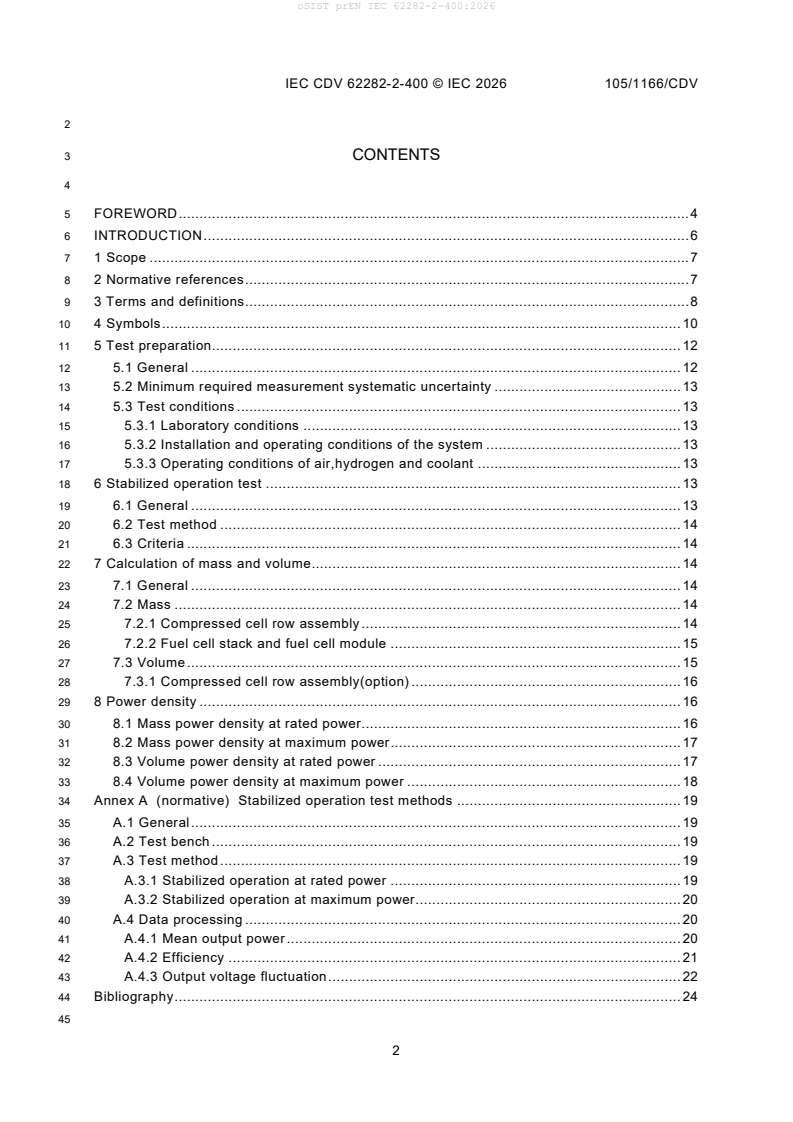
3 CONTENTS
5 FOREWORD . 4
6 INTRODUCTION . 6
7 1 Scope . 7
8 2 Normative references . 7
9 3 Terms and definitions . 8
10 4 Symbols . 10
11 5 Test preparation. 12
12 5.1 General . 12
13 5.2 Minimum required measurement systematic uncertainty . 13
14 5.3 Test conditions . 13
15 5.3.1 Laboratory conditions . 13
16 5.3.2 Installation and operating conditions of the system . 13
17 5.3.3 Operating conditions of air,hydrogen and coolant . 13
18 6 Stabilized operation test . 13
19 6.1 General . 13
20 6.2 Test method . 14
21 6.3 Criteria . 14
22 7 Calculation of mass and volume . 14
23 7.1 General . 14
24 7.2 Mass . 14
25 7.2.1 Compressed cell row assembly . 14
26 7.2.2 Fuel cell stack and fuel cell module . 15
27 7.3 Volume . 15
28 7.3.1 Compressed cell row assembly(option) . 16
29 8 Power density . 16
30 8.1 Mass power density at rated power. 16
31 8.2 Mass power density at maximum power . 17
32 8.3 Volume power density at rated power . 17
33 8.4 Volume power density at maximum power . 18
34 Annex A (normative) Stabilized operation test methods . 19
35 A.1 General . 19
36 A.2 Test bench . 19
37 A.3 Test method . 19
38 A.3.1 Stabilized operation at rated power . 19
39 A.3.2 Stabilized operation at maximum power . 20
40 A.4 Data processing . 20
41 A.4.1 Mean output power . 20
42 A.4.2 Efficiency . 21
43 A.4.3 Output voltage fluctuation . 22
44 Bibliography . 24
105/1066/CDV IEC CDV 62282-2-400 © IEC 2026
46 Figure 1 – Fuel cell power system components . 7
47 Figure 2 – Examples of a start-up and go operational test . 15
48 Figure 3 – Exploded view of cell area . 15
49 Figure A.1 – Example of a test station setup for fuel cell stack or fuel cell module . 19
51 Table 1 – Symbols and their meanings. 10
52 Table A.1 – High dynamic standard load profile . 20
IEC CDV 62282-2-400 © IEC 2026 105/1166/CDV
54 INTERNATIONAL ELECTROTECHNICAL COMMISSION
55 ____________
57 FUEL CELL TECHNOLOGIES – Part 2-400: Fuel cell modules –
58 Calculation of Rated Power and Power Density of a PEM stack and PEM
59 module
61 FOREWORD
62 1) The International Electrotechnical Commission (IEC) is a worldwide organization for standardization comprising
63 all national electrotechnical committees (IEC National Committees). The object of IEC is to promote international
64 co-operation on all questions concerning standardization in the electrical and electronic fields. To this end and
65 in addition to other activities, IEC publishes International Standards, Technical Specifications, Technical Reports,
66 Publicly Available Specifications (PAS) and Guides (hereafter referred to as "IEC Publication(s)"). Their
67 preparation is entrusted to technical committees; any IEC National Committee interested in the subject dealt with
68 may participate in this preparatory work. International, governmental and non-governmental organizations liaising
69 with the IEC also participate in this preparation. IEC collaborates closely with the International Organization for
70 Standardization (ISO) in accordance with conditions determined by agreement between the two organizations.
71 2) The formal decisions or agreements of IEC on technical matters express, as nearly as possible, an international
72 consensus of opinion on the relevant subjects since each technical committee has representation from all
73 interested IEC National Committees.
74 3) IEC Publications have the form of recommendations for international use and are accepted by IEC National
75 Committees in that sense. While all reasonable efforts are made to ensure that the technical content of IEC
76 Publications is accurate, IEC cannot be held responsible for the way in which they are used or for any
77 misinterpretation by any end user.
78 4) In order to promote international uniformity, IEC National Committees undertake to apply IEC Publications
79 transparently to the maximum extent possible in their national and regional publications. Any divergence between
80 any IEC Publication and the corresponding national or regional publication shall be clearly indicated in the latter.
81 5) IEC itself does not provide any attestation of conformity. Independent certification bodies provide conformity
82 assessment services and, in some areas, access to IEC marks of conformity. IEC is not responsible for any
83 services carried out by independent certification bodies.
84 6) All users should ensure that they have the latest edition of this publication.
85 7) No liability shall attach to IEC or its directors, employees, servants or agents including individual experts and
86 members of its technical committees and IEC National Committees for any personal injury, property damage or
87 other damage of any nature whatsoever, whether direct or indirect, or for costs (including legal fees) and
88 expenses arising out of the publication, use of, or reliance upon, this IEC Publication or any other IEC
89 Publications.
90 8) Attention is drawn to the Normative references cited in this publication. Use of the referenced publications is
91 indispensable for the correct application of this publication.
92 9) IEC draws attention to the possibility that the implementation of this document may involve the use of (a)
93 patent(s). IEC takes no position concerning the evidence, validity or applicability of any claimed patent rights in
94 respect thereof. As of the date of publication of this document, IEC had not received notice of (a) patent(s), which
95 may be required to implement this document. However, implementers are cautioned that this may not represent
96 the latest information, which may be obtained from the patent database available at https://patents.iec.ch. IEC
97 shall not be held responsible for identifying any or all such patent rights.
98 IEC 62282-4-200 has been prepared by IEC Technical Committee 105: Fuel cell technologies.
99 It is an International Standard.
100 The text of this International Standard is based on the following documents:
Draft Report on voting
105/XX/FDIS 105/XX/RVD
102 Full information on the voting for its approval can be found in the report on voting indicated in
103 the above table.
104 The language used for the development of this International Standard is English.
105/1066/CDV IEC CDV 62282-2-400 © IEC 2026
105 This document was drafted in accordance with ISO/IEC Directives, Part 2, and developed in
106 accordance with ISO/IEC Directives, Part 1 and ISO/IEC Directives, IEC Supplement, available
107 at www.iec.ch/members_experts/refdocs. The main document types developed by IEC are
108 described in greater detail at www.iec.ch/publications.
109 A list of all parts in the IEC 62282 series, published under the general title FUEL CELL
110 TECHNOLOGIES can be found on the IEC website.
111 The committee has decided that the contents of this document will remain unchanged until the
112 stability date indicated on the IEC website under webstore.iec.ch in the data related to the
113 specific document. At this date, the document will be
114 • reconfirmed,
115 • withdrawn, or
116 • revised.
IEC CDV 62282-2-400 © IEC 2026 105/1166/CDV
118 INTRODUCTION
119 It is essential to define the rated power of fuel cell stacks and modules, as well as to calculate
120 their volume and mass. This ensures complete and rigorous definition of system boundaries,
121 thereby avoiding unreasonable calculation practices such as adopting maximum power output
122 values paired with minimum stack volume parameters.
123 For this reason, harmonised definitions of rated power and volume/mass power density are
124 highly market-relevant. Such harmonisation facilitates a better understanding of stack and
125 module performance and enables fair, valid comparative evaluation, which is particularly
126 beneficial for system integrators.
127 The purpose of this document is to harmonise the calculation methods for the rated power and
128 power density of PEM fuel cell stacks and modules. It applies exclusively to proton exchange
129 membrane (PEM) fuel cell stacks and modules.
130 Although this document excludes fuel cell road vehicle applications, this standard may be
131 applicable to all other fuel cell applications, as it solely addresses stack and module
132 performance irrespective of the intended use case.
133 This document is not intended to restrict technological development. Any appliance using
134 materials or construction methods different from those specified herein may be assessed and
135 tested against the intent of these requirements. Where substantial equivalence is demonstrated,
136 the appliance shall be deemed compliant with this document.
105/1066/CDV IEC CDV 62282-2-400 © IEC 2026
137 FUEL CELL TECHNOLOGIES – Part 2-400: Fuel cell modules –
138 Calculation of Rated Power and Power Density of a PEM stack and PEM
139 module
141 1 Scope
142 This document specifies methods for calculating the rated power and power density of PEM fuel cell
143 stacks and modules.
144 To supply power to an application, the stack or module shall be integrated within a fuel cell
145 power system, as illustrated in Figure 1 in accordance with IEC 62282-2-100:2020.
146 This document applies to all PEM fuel cells, irrespective of their application and PEM technology
147 type, including high-temperature PEM fuel cells.
149 Figure 1 – Fuel cell power system components
150 Fuel cell modules may be fitted with or without enclosures, and can operate at substantial
151 pressurisation levels or near ambient pressure.
152 Since peripheral devices affect the net power output of the fuel cell power system, this standard
153 focuses on the stack and module in their standalone state prior to such peripheral influences,
154 as illustrated in Figure 1.
155 This document excludes the storage and delivery of fuel and oxidant to the fuel cell module.
156 2 Normative references
157 The following documents are referred to in the text in such a way that some or all of their content
158 constitutes requirements of this document. For dated references, only the edition cited applies.
IEC CDV 62282-2-400 © IEC 2026 105/1166/CDV
159 For undated references, the latest edition of the referenced document (including any
160 amendments) applies.
161 ISO1183-1,Plastics — Methods for determining the density of non-cellular plastics 一 Plastics —
162 Methods for determining the density of non-cellular plastics
163 ISO 10303-42,Industrial automation systems and integration — Product data representation and
164 exchange - Part 42: Integrated generic resource: Geometric and topological representation
165 ISO 10360 (all part),Geometrical product specifications(GPS) - Acceptance and reverification tests for
166 coordinate measuring machines(CMM)
167 ISO 14687:2025 ,Hydrogen fuel quality - Product specification
168 3 Terms and definitions
169 For the purposes of this document, the following terms and definitions apply.
170 ISO and IEC maintain terminology databases for use in standardization at the following
171 addresses:
172 • IEC Electropedia: available at http://www.electropedia.org/
173 • ISO Online browsing platform: available at http://www.iso.org/obp
174 3.1
175 Compressed cell row assembly
176 assembly of all successive MEAs and bipolar plates(include gas seal) compressed in the fuel cell
177 stack
178 Note 1 to entry: The compressed cell row assembly includes all dummy cell in the fuel cell stack.
179 Note 2 to entry: See figure 2.
180 3.2
181 fuel cell stack
182 assembly of cells, separators, cooling plates, manifolds and a supporting structure that
183 electrochemically converts, typically, hydrogen-rich gas and air reactants to DC power, heat
184 and other reaction products
185 [SOURCE: IEC 60050-485:2020, 485-06-01]
186 3.3
187 fuel cell module
188 assembly incorporating one or more fuel cell stacks and, if applicable, additional components,
189 that is intended to be integrated into a power system or a vehicle
190 Note 1 to entry: A fuel cell module comprises the following main components: one or more fuel cell stack(s), a
191 piping system for conveying fuels, oxidants and exhausts, electric connections for the power delivered by the
192 stack(s), and means for monitoring, control or both. Additionally, a fuel cell module can comprise: means for
193 conveying additional fluids (e.g. cooling media, inert gas), means for detecting normal and abnormal operating
194 conditions, enclosures or pressure vessels and module ventilation systems, and the required electronic
195 components for module operation and power conditioning.
196 [SOURCE: IEC 60050-485:2020, 485-09-03]
197 3.4
198 Rated power
199 maximum continuous electric power output that a fuel cell stack or a fuel cell module is designed
200 to achieve under normal operating conditions specified by the manufacturer
201 Note 1 to entry: The rated power is expressed in W.
105/1066/CDV IEC CDV 62282-2-400 © IEC 2026
202 [SOURCE: IEC 60050-485:2020, 485-09-01, modified – “a fuel cell power system”has been
203 replaced with“a fuel cell stack or a fuel cell module]
204 3.5
205 Rated current
206 maximum continuous electric current as specified by the manufacturer, at which the fuel cell
207 stack or the fuel cell module has been designed to operate
208 Note 1 to entry: the rated current is expressed in A.
209 [SOURCE: IEC 60050-485:2020, 485-12-02, modified –“a fuel cell power system”has been
210 replaced with“a fuel cell stack or a fuel cell module]
211 3.6
212 Maximum power
213 maximum electric power output that a fuel cell stack or a fuel cell module can be operated
214 specified by the manufacturer
215 Note 1 to entry: Maximum power can be higher than rated power.
216 [SOURCE: IEC 63341-3:2025, 3.1.7, modified –“a fuel cell power system”has been replaced
217 with“a fuel cell stack or a fuel cell module;” specified by the manufacturer”has been added.]
218 3.7
219 Maximum current
220 maximum electric current output that a fuel cell stack or a fuel cell module can be operated
221 specified by the manufacturer
222 Note 1 to entry: Maximum current can be higher than rated current.
223 3.8
224 Output power
225 power generated by the fuel cell stack or the fuel cell module and available for external use
226 [SOURCE: IEC 63341-3:2025, 3.1.9, modified –“the fuel cell power system”has been replaced
227 with“the fuel cell stack or the fuel cell module;The note 1 to entry has been deleted;The note 2
228 to entry has been deleted.]
229 3.9
230 Efficiency
231 ratio of the mean single cell output voltage of a fuel cell stack or a fuel cell module to 1.254.
232 3.10
233 Mass power density
234 ratio of the rated power or maximum power to the dry mass of a compressed cell row assembly,
235 fuel cell stack or fuel cell module
236 3.11
237 Volume power density
238 ratio of the rated power or maximum power to the volume of a compressed cell row assembly,
239 a fuel cell stack or a fuel cell module
240 3.12
241 Steady state
242 state of a physical system in which the relevant characteristics remain constant with time
243 [SOURCE: IEC 60050-485:2020, 485-21-05]
IEC CDV 62282-2-400 © IEC 2026 105/1166/CDV
244 3.13
245 Cell area
246 outer contour projected area of a single cell perpendicular to the direction of current flow
247 Note 1 to entry: See Figure 3.
248 [SOURCE: IEC 60050-485:2020, 485-05-04, modified –”outer contour” has been add before
249 “Geometric”;The note 1 to entry has been deleted]
250 3.14
251 conditioning
252 preliminary step that is required to properly operate a fuel cell to achieve a desired performance
253 following a protocol specified by the manufacturer
254 Note 1 to entry: The conditioning can include reversible processes, or irreversible processes, or both depending on
255 the cell technology.
256 [SOURCE: IEC 60050-485:2020, 485-11-08]
257 4 Symbols
258 Table 1 lists the symbols and their meanings used in this document to represent the electrical
259 performance in the appropriate units.
260 Table 1 – Symbols and their meanings
Symbols Definition Unit
mass of compressed cell row assembly
M kg
RCA
quantity of bipolar plate included in compressed cell row assembly
n
mass of a bipolar plat
M kg
BP
quantity of MEA included dummy cell in compressed cell row assembly
m
mass of a MEA
M kg
GS
volume of compressed cell row assembly
V L
RCA
cell area 2
S dm
CA
distance between the two end plates of fuel cell stack
dm
L
EP
mass power density of compressed cell row assembly at rated power
PD W/kg
m,Rated,RCA
mass power density of fuel cell stack at rated power
PD W/kg
m,Rated,FCS
mass power density of fuel cell module at rated power
PD W/kg
m,Rated,FCM
rated power of fuel cell stack
P W
rated,FCS
rated power of fuel cell module
P W
rated,FCM
mass of fuel cell stack
M kg
FCS
mass of fuel cell module
M kg
FCM
mass power density of compressed cell row assembly at maximum power
PD W/kg
m,max,RCA
105/1066/CDV IEC CDV 62282-2-400 © IEC 2026
Symbols Definition Unit
mass power density of fuel cell stack at maximum power
PD
W/kg
m,max,FCS
mass power density of fuel cell module at maximum power
PD
W/kg
m,max,FCM
maximum power of fuel cell stack
P
W
max,FCS
maximum power of fuel cell module
P
W
max,FCM
volume power density of compressed cell row assembly at rated power
PD
W/L
v,Rated,RCA
volume power de
...