

prEN IEC 60041:2026
(Main)Field acceptance tests to determine the hydraulic performance of hydraulic turbines, storage pumps and pump-turbines
- Status
- Not Published
- Publication Date
- 14-Feb-2028
- Technical Committee
- CLC/SR 4 - Hydraulic turbines
- Drafting Committee
- IEC/TC 4 - IEC_TC_4
- Current Stage
- 4020 - Enquiry circulated - Enquiry
- Start Date
- 24-Jul-2026
- Due Date
- 29-Dec-2023
- Completion Date
- 24-Jul-2026

prEN IEC 60041:2026 is a CLC/IEC draft standard for field acceptance tests to determine the hydraulic performance of hydraulic turbines, storage pumps and pump-turbines. It specifies how to measure, calculate and compare discharge, power, efficiency, specific hydraulic energy, speed and transient behaviour against contractual guarantees, so owners, suppliers and test teams can use the same basis for acceptance.
What does prEN IEC 60041:2026 specify?
prEN IEC 60041:2026 covers acceptance testing of hydraulic turbines, storage pumps and pump-turbines on site. The standard focuses on the main hydraulic guarantees used in contracts and on the methods needed to verify them in field conditions.
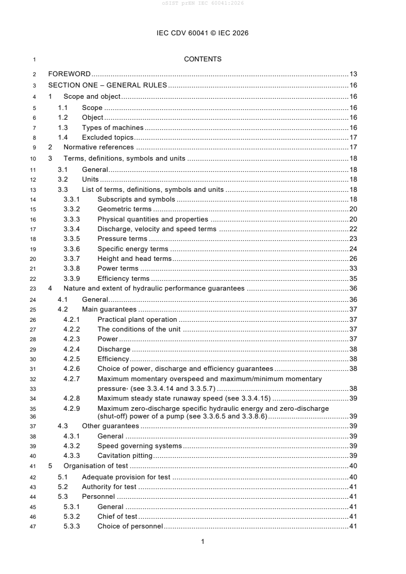
It is organised in four main parts:
- Section One - General Rules, Clauses 1 to 5
- Section Two - Execution of test for the determination of the steady state performance of the machine, Clauses 6 to 7
- Section Three - Execution of test for the determination of the transient characteristic of the machine, Clauses 8 to 9
- Section Four - Methods of measurement, Clauses 10 to 17
The standard also includes annexes for uncertainty analysis, physical data and specialised measurement methods. The main covered guarantees are power, discharge, efficiency, maximum momentary overspeed, maximum/minimum momentary pressure and maximum steady state runaway speed. Other guarantees, such as speed governing systems and cavitation pitting, are outside the covered scope.
| Annex | What it covers |
|---|---|
| Annex A | Systematic uncertainties in performance measurements at steady state conditions |
| Annex B | Rejection of outliers |
| Annex C | Analysis of the random uncertainty for a test at constant operating conditions |
| Annex D | Analysis of the random uncertainties for a test over a range of operating conditions |
| Annex E | Physical data |
| Annex F | Derivation of the equation for the specific hydraulic energy of a machine |
| Annex G | Measurement of electric power - correction for a single-phase measuring system |
| Annex H | Thermodynamic method - balance of power and computation of the specific mechanical energy |
| Annex I | Acoustic scintillation method of discharge measurement |
| Annex J | Acoustic transit time (ATT) method of discharge measurement |
| Annex K | Digital measurement of pressure fluctuations - guideline for signal processing |
What are the key requirements of prEN IEC 60041:2026?
prEN IEC 60041:2026 requires the contract, test setup, instrumentation and evaluation method to be agreed before acceptance testing starts. It then sets out how to run the test, reduce the results to the specified conditions, and compare them with the guarantees while taking measurement uncertainty into account.
Guarantees and contract data
Clause 4 requires contracts to define the main hydraulic guarantees and the values on which they are based. For a regulated or non-regulated machine, the contract should cover the guaranteed operating quantities and the site data needed to interpret them.
In practice, the purchaser is responsible for providing complete and accurate data for basins, waterways, inlet and outlet structures, driven or driving machinery, governors, valves, gates and related equipment. This matters because the acceptance test depends on the actual hydraulic installation, not only on the machine itself.
Clause 4 also states that the purchaser specifies the water quality, water temperature and the plant energy terms used as the basis for the guarantees. That keeps the test aligned with the conditions used when the performance was promised.
Test organisation and traceability
Clause 5 sets the framework for running the test. It covers adequate provision for the test, test authority, personnel, the chief of test, site preparation, agreement on the procedure, the date and programme, the data acquisition and processing system, dispute or repetition, inspection after the test and the final report.
In practice, this means the test must be organised like a controlled engineering exercise, not an informal site check. Drawings and relevant data have to be submitted, the site inspected and the instrumentation calibrated and checked before readings are accepted.
The clause on the data acquisition and processing system is important because it requires observation sheets, calibration of components, manual readings where needed, preliminary calculations and signed readings and recordings. That gives the acceptance result traceability if the test is challenged later.
Steady-state performance testing
Clauses 6 and 7 cover the steady-state acceptance test. They address the general procedure, the number of runs, readings and points, recommended procedures, and special procedures for double regulated turbines and for single regulated or double regulated pumps.
Clause 6 also defines the test conditions that must be met during a run, including limits on fluctuations and variations, and how far average specific hydraulic energy and rotational speed may deviate from the specified values. This matters because the measured point only counts if the machine is sufficiently close to the target condition.
Clause 7 explains how results are compiled, converted and corrected to the specified conditions. It also requires test curves, uncertainty analysis and comparison with guarantees. The standard therefore does not treat raw site readings as final results.
A key point in Clause 7 is the temperature influence on efficiency. If the water temperature during the test differs from the specified temperature, efficiency may be converted using the method in this clause, but only for the machine types listed in Table 1. That is important for buyers and suppliers because the contract must match the machine type and reference temperature.
Transient behaviour
Clauses 8 and 9 cover transient characteristic testing. The standard addresses speed variations, pressure variations and the movement of shut-off devices during transient events.
In practice, this is the part used to check overspeed and pressure behaviour during events such as load rejection or power failure. Clause 9 then shows how the transient results are converted and compared with the guarantees.
Measurement methods
Clauses 10 to 17 define the measurement methods used to determine the quantities needed for acceptance. Clause 10 states that the test compares achieved performance with the supplier’s guarantees and involves specific hydraulic energy, discharge, mechanical power, rotational speed and efficiency.
Efficiency may be determined from hydraulic power and mechanical power, or more directly by the thermodynamic method using the water temperature rise due to losses. The thermodynamic method is useful when discharge measurement is difficult or introduces too much uncertainty.
Clause 11 gives multiple discharge methods, including current-meter methods, Pitot tubes, pressure-time method, dye dilution, weirs, standardized differential pressure devices, volumetric gauging, acoustic transit time and acoustic scintillation. This gives the test team several choices depending on the site and flow arrangement.
Clauses 12 to 14 cover specific hydraulic energy, pressure measurement, free water level measurement, power measurement and rotational speed measurement. Clauses 15 to 17 add the thermodynamic method, index tests and comparative tests. Together, these clauses let the test team select the measurement route that fits the installation and the required uncertainty.
Uncertainty and acceptance decision
Annexes A to D provide the uncertainty framework, including systematic and random uncertainty analysis, outlier rejection and examples. Clause 7 and Clause 9 require the measurement uncertainty to be considered when judging whether the guarantees have been met.
In practice, the machine passes only if the measured or converted values fall within the guaranteed limits once uncertainty and any contractual tolerances are taken into account. That is the acceptance rule that matters for commercial decisions.
What terms does prEN IEC 60041:2026 define?
- Regulated machine - A machine in which the flow is controlled by a flow-controlling device such as guide vanes, needle(s) and/or runner/impeller blades.
- Single regulated machine - A regulated machine with one flow-controlling device.
- Double regulated machine - A regulated machine with two flow-controlling devices.
- Non-regulated machine - A machine with no flow-controlling device.
- Net positive suction specific energy (NPSE) - The suction energy margin used in the standard to express cavitation-related conditions at the machine inlet.
- Net positive suction head (NPSH) - The head form corresponding to NPSE.
- Index discharge - Discharge obtained from a relative, uncalibrated flow measurement.
- Relative efficiency - The efficiency at a given operating condition divided by a reference value.
Who uses prEN IEC 60041:2026?
prEN IEC 60041:2026 is used by purchasers, suppliers, owners and site test teams for hydroelectric and pumped-storage projects. It is also relevant to quality managers, commissioning engineers, test laboratories and consultants who need a common method for contractual acceptance.
In practice, these users apply the standard to define guarantees, choose the test method, set up instrumentation, run acceptance tests, evaluate uncertainty and document the final result. It is especially relevant when a project needs a defensible comparison between measured field performance and guaranteed hydraulic performance.
What changed in prEN IEC 60041:2026 from the previous edition?
prEN IEC 60041:2026 states that it supersedes 4/453/CD and 4/466A/CC.
Which standards are used with prEN IEC 60041:2026?
- IEC 60193 - Used for the Thoma number (cavitation factor) and referenced in the machine-type discussion and efficiency conversion table.
- IEC 60034-2-2 - Used for the calorimetric method for bearing losses in Clause 13.
- ISO 1438 - Used for weir discharge formulae in Clause 11.6.
- ISO 4373 - Used for free water level measurement in Clause 12.5.
What does the prEN IEC 60041:2026 document contain?
The document contains detailed test procedures, measurement methods, computation rules and uncertainty methods for field acceptance testing. Its figures show machine layouts, speed and pressure transients, and examples of low-head, medium-head, high-head and Pelton arrangements.
The clauses include worked methods for discharge measurement, specific hydraulic energy, power, rotational speed, thermodynamic efficiency, index tests and comparative tests. These are the practical parts a test engineer uses to turn site readings into acceptance results.
The annexes add uncertainty analysis, physical property data, derivation of the specific hydraulic energy equation, electrical power correction for single-phase systems, thermodynamic balance equations and specialised acoustic discharge methods. Annex K provides guidance for digital processing of pressure fluctuations, which is useful where transient pressure signals need filtering and analysis.
Relations
- Effective Date
- 22-Jan-2023
Get Certified
Connect with accredited certification bodies for this standard

DNV
DNV is an independent assurance and risk management provider.

Lloyd's Register
Lloyd's Register is a global professional services organisation specialising in engineering and technology.
DNV Energy Systems
Energy and renewable energy certification.
Sponsored listings
Frequently Asked Questions
prEN IEC 60041:2026 is a draft published by CLC. Its full title is "Field acceptance tests to determine the hydraulic performance of hydraulic turbines, storage pumps and pump-turbines". This standard covers: Field acceptance tests to determine the hydraulic performance of hydraulic turbines, storage pumps and pump-turbines
Field acceptance tests to determine the hydraulic performance of hydraulic turbines, storage pumps and pump-turbines
prEN IEC 60041:2026 is classified under the following ICS (International Classification for Standards) categories: 27.140 - Hydraulic energy engineering. The ICS classification helps identify the subject area and facilitates finding related standards.
prEN IEC 60041:2026 has the following relationships with other standards: It is inter standard links to EN 60041:1994. Understanding these relationships helps ensure you are using the most current and applicable version of the standard.
prEN IEC 60041:2026 is available in PDF format for immediate download after purchase. The document can be added to your cart and obtained through the secure checkout process. Digital delivery ensures instant access to the complete standard document.
Standards Content (Sample)
SLOVENSKI STANDARD
01-september-2026
Terenski prevzemni preskusi za ugotavljanje zmogljivosti vodnih turbin,
akumulacijskih črpalk in črpalnih turbin
Field acceptance tests to determine the hydraulic performance of hydraulic turbines,
storage pumps and pump-turbines
Abnahmeversuche zur Bestimmung der hydraulischen Eigenschaften von
Wasserturbinen, Speicherpumpen und Pumpturbinen
Essais de réception sur place des turbines hydrauliques, pompes d'accumulation et
pompes-turbines, en vue de la détermination de leurs performances hydrauliques
Ta slovenski standard je istoveten z: prEN IEC 60041:2026
ICS:
27.140 Vodna energija Hydraulic energy engineering
2003-01.Slovenski inštitut za standardizacijo. Razmnoževanje celote ali delov tega standarda ni dovoljeno.
4/557/CDV
COMMITTEE DRAFT FOR VOTE (CDV)
PROJECT NUMBER:
IEC 60041 ED4
DATE OF CIRCULATION: CLOSING DATE FOR VOTING:
2026-07-24 2026-10-16
SUPERSEDES DOCUMENTS:
4/453/CD, 4/466A/CC
IEC TC 4 : HYDRAULIC TURBINES
SECRETARIAT: SECRETARY:
Canada Mrs Christine Geraghty
OF INTEREST TO THE FOLLOWING COMMITTEES: HORIZONTAL FUNCTION(S):
ASPECTS CONCERNED:
SUBMITTED FOR CENELEC PARALLEL VOTING NOT SUBMITTED FOR CENELEC PARALLEL VOTING
Attention IEC-CENELEC parallel voting
The attention of IEC National Committees, members of
CENELEC, is drawn to the fact that this Committee Draft
for Vote (CDV) is submitted for parallel voting.
The CENELEC members are invited to vote through the
CENELEC online voting system.
This document is still under study and subject to change. It should not be used for reference purposes.
Recipients of this document are invited to submit, with their comments, notification of any relevant patent rights of
which they are aware and to provide supporting documentation.
Recipients of this document are invited to submit, with their comments, notification of any relevant “In Some
Countries” clauses to be included should this proposal proceed. Recipients are reminded that the CDV stage is
the final stage for submitting ISC clauses. (SEE AC/22/2007 OR NEW GUIDANCE DOC).
TITLE:
Field acceptance tests to determine the hydraulic performance of hydraulic turbines, storage
pumps and pump-turbines
PROPOSED STABILITY DATE: 2028
NOTE FROM TC/SC OFFICERS:
download this electronic file, to make a copy and to print out the content for the sole purpose of preparing National
Committee positions. You may not copy or "mirror" the file or printed version of the document, o r any part of it,
for any other purpose without permission in writing from IEC.
IEC CDV 60041 © IEC 2026
1 CONTENTS
2 FOREWORD . 13
3 SECTION ONE – GENERAL RULES . 16
4 1 Scope and object . 16
5 1.1 Scope . 16
6 1.2 Object . 16
7 1.3 Types of machines . 16
8 1.4 Excluded topics. 17
9 2 Normative references . 17
10 3 Terms, definitions, symbols and units . 18
11 3.1 General . 18
12 3.2 Units . 18
13 3.3 List of terms, definitions, symbols and units . 18
14 3.3.1 Subscripts and symbols . 18
15 3.3.2 Geometric terms . 20
16 3.3.3 Physical quantities and properties . 20
17 3.3.4 Discharge, velocity and speed terms . 22
18 3.3.5 Pressure terms . 23
19 3.3.6 Specific energy terms . 24
20 3.3.7 Height and head terms. 26
21 3.3.8 Power terms . 33
22 3.3.9 Efficiency terms . 35
23 4 Nature and extent of hydraulic performance guarantees . 36
24 4.1 General . 36
25 4.2 Main guarantees . 37
26 4.2.1 Practical plant operation . 37
27 4.2.2 The conditions of the unit . 37
28 4.2.3 Power . 37
29 4.2.4 Discharge . 38
30 4.2.5 Efficiency . 38
31 4.2.6 Choice of power, discharge and efficiency guarantees . 38
32 4.2.7 Maximum momentary overspeed and maximum/minimum momentary
,
33 pressure (see 3.3.4.14 and 3.3.5.7) . 38
34 4.2.8 Maximum steady state runaway speed (see 3.3.4.15) . 39
35 4.2.9 Maximum zero-discharge specific hydraulic energy and zero-discharge
36 (shut-off) power of a pump (see 3.3.6.5 and 3.3.8.6) . 39
37 4.3 Other guarantees . 39
38 4.3.1 General . 39
39 4.3.2 Speed governing systems . 39
40 4.3.3 Cavitation pitting . 39
41 5 Organisation of test . 40
42 5.1 Adequate provision for test . 40
43 5.2 Authority for test . 41
44 5.3 Personnel . 41
45 5.3.1 General . 41
46 5.3.2 Chief of test . 41
47 5.3.3 Choice of personnel . 41
IEC CDV 60041 © IEC 2026
48 5.3.4 Presence at test . 41
49 5.4 Preparation for test . 41
50 5.4.1 Submission of drawings and relevant data . 41
51 5.4.2 Inspection on site . 41
52 5.4.3 Measurements before test . 42
53 5.5 Agreement on test procedure . 42
54 5.5.1 Approval of procedure . 42
55 5.5.2 Date of test . 42
56 5.5.3 General programme . 42
57 5.6 Data Acquisition and Processing System . 43
58 5.6.1 General . 43
59 5.6.2 General requirements . 43
60 5.6.3 Observation sheets . 44
61 5.6.4 Components of a Data Acquisition System . 45
62 5.6.5 Calibration of components . 47
63 5.6.6 Check of the data acquisition system . 47
64 5.6.7 Manual instrument readings . 47
65 5.6.8 Data acquisition and data processing . 47
66 5.6.9 Preliminary calculation . 48
67 5.6.10 Signing of readings and recordings . 48
68 5.7 Procedure in case of dispute or repetition . 48
69 5.8 Inspection after test . 48
70 5.9 Final report . 48
71 5.9.1 Preparation of final report . 48
72 5.9.2 Content. 48
73 SECTION TWO – EXECUTION OF TEST FOR THE DETERMINATION OF THE
74 STEADY STATE PERFORMANCE OF THE MACHINE . 50
75 6 Test conditions and procedure . 50
76 6.1 General test procedure . 50
77 6.1.1 Methods of measurement . 50
78 6.1.2 Number of runs, readings and points . 50
79 6.1.3 Recommended test procedures . 50
80 6.1.4 Particular procedure for double regulated turbines . 51
81 6.1.5 Particular procedure for single regulated or double regulated pumps . 51
82 6.2 Test conditions to be fulfilled . 52
83 6.2.1 General . 52
84 6.2.2 Fluctuations and variations during a run (see 3.1) . 52
85 6.2.3 Deviations of average specific hydraulic energy and rotational speed
86 from specified values during a run (see 3.1) . 52
87 6.2.4 Net positive suction specific energy (see 3.3.6.9) and tailwater level
88 during the measurement of a point (see 3.1) . 53
89 7 Computation and analysis of results . 53
90 7.1 Computation of test results . 53
91 7.1.1 Compilation of a point . 53
92 7.1.2 Conversion and correction of test results to specified conditions . 53
93 7.1.3 Test curves . 57
94 7.2 Uncertainties in measurements and presentation of results . 58
95 7.2.1 Definition of error . 58
96 7.2.2 Definition of uncertainty . 58
IEC CDV 60041 © IEC 2026
97 7.2.3 Types of errors . 58
98 7.2.4 Total uncertainty . 60
99 7.2.5 Analysis of results . 60
100 7.2.6 Presentation of results . 60
101 7.3 Comparison with guarantees . 61
102 7.3.1 General . 61
103 7.3.2 Power (see 4.2.3) . 61
104 7.3.3 Discharge (see 4.2.4) . 63
105 7.3.4 Efficiency (see 4.2.5) . 64
106 SECTION THREE – EXECUTION OF TEST FOR THE DETERMINATION OF THE
107 TRANSIENT CHARACTERISTIC OF THE MACHINE . 69
108 8 Test conditions and procedure . 69
109 8.1 Test conditions . 69
110 8.1.1 General . 69
111 8.1.2 Speed variations . 69
112 8.1.3 Pressure variations . 69
113 8.2 Test procedure and instrumentation . 70
114 8.2.1 General requirements . 70
115 8.2.2 Measurement of speed variations . 70
116 8.2.3 Measurement of pressure variations . 70
117 8.2.4 Measurement of the movement of shut-off devices . 70
118 9 Computation and analysis of results . 70
119 9.1 Conversion of results . 70
120 9.2 Comparison with guarantees . 71
121 9.2.1 Nature and extent of guarantees . 71
122 9.2.2 Fulfilment of guarantees . 72
123 SECTION FOUR – METHODS OF MEASUREMENT . 73
124 10 Methods of measurement . 73
125 10.1 General . 73
126 10.2 Efficiency . 73
127 10.3 Hydraulic power . 73
128 10.3.1 Definition . 73
129 10.3.2 Mass flow rate . 74
130 10.3.3 Hydraulic power correction . 74
131 10.3.4 Water density . 74
132 10.4 Mechanical power . 75
133 10.5 Machine openings . 75
134 11 Discharge . 75
135 11.1 General . 75
136 11.1.1 Recommendations at the development stage . 75
137 11.1.2 Choice of the method of measurement . 75
138 11.1.3 Uncertainty of measurement . 76
139 11.1.4 General requirements . 76
140 11.1.5 Computational fluid dynamics (CFD) . 77
141 11.2 Current-meter method . 77
142 11.2.1 Principle of velocity-area method . 77
143 11.2.2 General requirements . 77
144 11.2.3 Measurements in closed conduits (penstocks) . 79
IEC CDV 60041 © IEC 2026
145 11.2.4 Measurements in short penstocks or intake structures . 80
146 11.2.5 Measurements in open channels . 83
147 11.2.6 Computation of discharge . 85
148 11.2.7 Uncertainty of measurement (see 11.1.3) . 86
149 11.3 Pitot tubes . 86
150 11.3.1 General . 86
151 11.3.2 Standardized Pitot tubes . 86
152 11.3.3 Non-standard devices . 86
153 11.4 Pressure-time method . 87
154 11.4.1 Principle of the method . 87
155 11.4.2 General requirements . 89
156 11.4.3 Measurement Methods . 91
157 11.4.4 Signal conditioning, data acquisition system and recordings . 93
158 11.4.5 Checking of the pressure measurements . 94
159 11.4.6 Computation of discharge . 95
160 11.4.7 Uncertainty of measurement . 97
161 11.5 Dye dilution method (Tracer methods). 98
162 11.5.1 Principle of the method . 98
163 11.5.2 Variants of the method . 100
164 11.5.3 Choice and properties of dye . 101
165 11.5.4 Setting up of initial and standard solution . 101
166 11.5.5 Types and calibration of fluorometer . 106
167 11.5.6 Injecting and extraction positions and methods . 108
168 11.5.7 Evaluation of measurement . 110
169 11.5.8 Uncertainty of measurement . 111
170 11.6 Weirs . 111
171 11.6.1 Principle of measurement . 111
172 11.6.2 Description of the measuring device . 111
173 11.6.3 Conditions of installation . 112
174 11.6.4 Measurement of head . 113
175 11.6.5 Discharge formulae. 116
176 11.6.6 Uncertainty of measurement (see 11.1.3) . 116
177 11.7 Standardized differential pressure devices . 116
178 11.7.1 Principle of the method . 116
179 11.7.2 Field of application . 117
180 11.7.3 Uncertainty of measurement . 117
181 11.8 Volumetric gauging method . 118
182 11.8.1 Principle of the method . 118
183 11.8.2 Basins for volumetric measurements . 118
184 11.8.3 Operation of measurement . 119
185 11.8.4 Analysis of the test results . 120
186 11.8.5 Uncertainty of measurement (see 11.1.3) . 120
187 11.9 Acoustic transit time. 121
188 11.9.1 General . 121
189 11.9.2 Principle of measurement . 121
190 11.9.3 Methods of discharge calculation . 123
191 11.9.4 Methods of velocity calculation . 127
192 11.9.5 Methods of transit time determination . 129
193 11.9.6 Methods of acoustic signal detection and qualification . 130
IEC CDV 60041 © IEC 2026
194 11.9.7 Tests . 130
195 11.9.8 Selection of measuring section and conditions of installation . 130
196 11.9.9 Conditions of use and limitations . 132
197 11.9.10 Agreement Issues . 132
198 11.9.11 Uncertainty of measurement . 132
199 12 Specific hydraulic energy of the machine . 133
200 12.1 General . 133
201 12.1.1 Object . 133
202 12.1.2 Method of determination . 133
203 12.1.3 Steady-state conditions . 133
204 12.2 Determination of the specific hydraulic energy . 133
205 12.2.1 Measuring sections . 133
206 12.2.2 Reference levels . 134
207 12.2.3 Water density . 136
208 12.2.4 Specific kinetic energy . 136
209 12.2.5 Simplified formulae . 136
210 12.3 Determination of the net positive suction specific energy . 143
211 12.3.1 Definition . 143
212 12.3.2 Simplified formulae . 143
213 12.4 Pressure measurements . 144
214 12.4.1 Choice of pressure measuring section . 144
215 12.4.2 Number and location of pressure taps . 145
216 12.4.3 Pressure taps . 145
217 12.4.4 Gauge piping . 146
218 12.4.5 Measuring apparatus . 147
219 12.4.6 Checking of pressure gauges . 150
220 12.4.7 Vacuum measurements . 151
221 12.5 Free water level measurements . 151
222 12.5.1 General . 151
223 12.5.2 Choice of water level measuring sections . 152
224 12.5.3 Number of measuring points in a measuring section . 152
225 12.5.4 Measuring apparatus . 152
226 12.6 Determination of the specific hydraulic energy measurement uncertainty . 156
227 13 Power . 156
228 13.1 Indirect method of power measurement. 156
229 13.1.1 General . 156
230 13.1.2 Electrical power Pa . 157
231 13.1.3 Determination of losses . 165
232 13.1.4 Uncertainty of measurement . 171
233 13.2 Bearing losses . 171
234 13.2.1 General . 171
235 13.2.2 Calculation of thrust bearing losses . 171
236 13.2.3 Calculation of guide bearing losses . 172
237 13.2.4 Hydraulic thrust measurement . 173
238 14 Rotational speed . 173
239 14.1 General . 173
240 14.2 Speed measurements . 173
241 14.3 Uncertainty of measurements . 174
242 15 Thermodynamic method for measuring efficiency . 174
IEC CDV 60041 © IEC 2026
243 15.1 General . 174
244 15.1.1 Principle . 174
245 15.1.2 Excluded topics and limitations . 174
246 15.1.3 Instrumentation . 174
247 15.2 Efficiency and specific mechanical energy . 175
248 15.3 Procedure for measurement of specific mechanical energy . 176
249 15.3.1 General . 176
250 15.3.2 Direct operating procedure . 178
251 15.3.3 Cross check of mechanical energy. 178
252 15.3.4 Thermometer calibration . 179
253 15.4 Apparatus . 179
254 15.4.1 Main measurements . 179
255 15.4.2 Auxiliary measurements . 181
256 15.5 Test conditions to be fulfilled . 181
257 15.5.1 Measuring sections and sampling conditions . 181
258 15.5.2 Particular flow arrangements . 184
259 15.5.3 Unfavourable operating conditions . 184
260 15.6 Corrective terms . 184
261 15.6.1 General . 184
262 15.6.2 Variations of temperature . 184
263 15.6.3 Extraneous heat exchange . 185
264 15.6.4 Limit of corrections . 186
265 15.7 Uncertainty of measurement . 187
266 15.7.1 General . 187
267 15.7.2 Evaluation procedure of the energy distribution . 187
268 16 Index tests . 188
269 16.1 General . 188
270 16.1.1 Object . 188
271 16.1.2 Definition of index value and relative value . 189
272 16.1.3 Applications . 189
273 16.2 Index discharge measurement . 190
274 16.2.1 General . 190
275 16.2.2 Index discharge measurement by differential pressure methods . 190
276 16.2.3 Index discharge measurement by velocity measurement methods . 194
277 16.2.4 Relative discharge measurement by means of the regulating apparatus
278 device . 194
279 16.2.5 Other methods of obtaining relative discharge . 195
280 16.3 Measurement of other quantities . 195
281 16.3.1 Specific hydraulic energy . 195
282 16.3.2 Power . 195
283 16.3.3 Rotational speed. 195
284 16.3.4 Machine openings . 195
285 16.4 Computation of results . 195
286 16.5 Uncertainty of measurement, considerations and evaluation . 196
287 16.5.1 General . 196
288 16.5.2 Winter Kennedy coefficient and changes in velocity distribution . 196
289 16.5.3 Multiple velocity inputs for reducing uncertainty and as a base for
290 analysing uncertainty . 196
291 17 Comparative tests . 198
IEC CDV 60041 © IEC 2026
292 Annex A (informative) Systematic uncertainties in performance measurements at
293 steady state conditions . 200
294 A.1 Usual values of systematic uncertainties in the various quantities . 200
295 A.2 Uncertainty analysis for thermodynamic test . 202
296 A.2.1 General . 202
297 A.2.2 Uncertainty in specific mechanical energy E . 202
m
298 A.2.3 Uncertainty in specific hydraulic energy E . 205
299 A.3 Example of calculation of systematic uncertainty in the specific hydraulic
300 energy of machine and in the derived efficiency . 206
301 A.4 Example of calculation of systematic uncertainty in the specific mechanical
302 energy at runner and in the derived efficiency . 207
303 A.5 Evaluation procedure of the energy distribution . 211
304 A.5.1 Measuring arrangement according to 15.5.1.3.1, “Open measuring
305 section”: . 211
306 A.5.2 Measuring arrangement according to 15.5.1.3.2, “Closed measuring
307 section”: . 214
308 A.6 Uncertainty for a comparative test . 214
309 Annex B (informative) Rejection of outliers . 215
310 Annex C (informative) Analysis of the random uncertainty for a test at constant
311 operating conditions . 217
312 C.1 General . 217
313 C.2 Standard deviation . 217
314 C.3 Confidence levels . 218
315 C.4 Student’s t distribution . 218
316 C.5 Maximum permissible value of uncertainty . 219
317 C.6 Example of calculation . 219
318 Annex D (informative) Analysis of the random uncertainties for a test over a range of
319 operating conditions . 221
320 D.1 General remarks . 221
321 D.2 Determination of the best smooth curve . 221
322 D.3 Estimation of uncertainty . 222
323 D.4 Example of calculation . 223
324 Annex E (normative) Physical data . 225
325 E.1 Acceleration due to gravity as a function of latitude and altitude . 225
326 E.2 Density of water . 226
327 E.3 Density of air . 227
328 E.4 Isothermal Throttling coefficient of water . 229
329 E.5 Specific heat capacity of water . 231
330 E.6 Vapour pressure of distilled water . 233
331 E.7 Formulation of the thermodynamic properties of sea water . 233
332 E.8 Formulation of the thermodynamic properties of water . 233
333 E.9 Dynamic viscosity of the water . 235
334 Annex F (normative) Derivation of the equation for the specific hydraulic energy of a
335 machine . 238
336 F.1 Theoretical equation . 238
337 F.2 Specific pressure energy term . 238
338 F.3 Specific potential energy term . 239
339 F.4 Practical equation . 239
340 Annex G (normative) Measurement of electric power – Determination of the correction
341 for a single-phase measuring system . 240
IEC CDV 60041 © IEC 2026
342 Annex H (normative) Thermodynamic method – Balance of power and computation of
343 the specific mechanical energy . 242
344 H.1 Extracting a discharge q . 242
345 H.2 Adding a discharge q . 243
346 Annex I (informative) Acoustic scintillation method of discharge measurement . 245
347 I.1 General . 245
348 I.2 Principles of Measurement . 245
349 I.2.1 General . 245
350 I.2.2 Sequence of Measurements .
...