


IEC 61753-1-3:2014
(Main)Fibre optic interconnecting devices and passive components - Performance standard - Part 1-3: General and guidance for single-mode fibre optic connector and cable assembly for industrial environment, Category I
General Information
- Abstract
IEC 61753-1-3:2014 defines the minimum initial performance, test and measurement requirements and severities which a connector or cable assembly with single-mode fibres needs to satisfy in order to be categorized as meeting IEC Category I (industrial environment). Category I is an additional environmental category to C, U, O and E already described in IEC 61753-1. Category I is based on the MICE Table described in ISO/IEC 24702. The performance tests evaluate the product for two basic acceptance criteria: mechanical integrity and optical transmission requirements, by simulating the effects of exposure to the environment in which it will be installed, simulating installation and intervention conditions, and evaluating specified features of the product. The defined performance test procedures simulate the situation in a mated condition under use in an industrial environment. It is not the intention to simulate the situation:
- when being mated or demated;
- during the assembling of the connector;
- during transportation and storage of the connector. Reliability tests for life time expectations are not covered by this standard. Keywords: single-mode fibres, IEC Category I (industrial environment), MICE Table
- Status
- Withdrawn
- Publication Date
- 22-May-2014
- Withdrawal Date
- 29-Dec-2022
- Technical Committee
- SC 86B - Fibre optic interconnecting devices and passive components
- Current Stage
- WPUB - Publication withdrawn
- Start Date
- 03-Jan-2023
- Completion Date
- 30-Dec-2022
Buy Documents



IEC 61753-1-3:2014 - Fibre optic interconnecting devices and passive components - Performance standard - Part 1-3: General and guidance for single-mode fibre optic connector and cable assembly for industrial environment, Category I Released:5/23/2014
IEC 61753-1-3:2014 - Fibre optic interconnecting devices and passive components - Performance standard - Part 1-3: General and guidance for single-mode fibre optic connector and cable assembly for industrial environment, Category I Released:5/23/2014
Relations
- Effective Date
- 05-Sep-2023
Buy Documents
IEC 61753-1-3:2014 - Fibre optic interconnecting devices and passive components - Performance standard - Part 1-3: General and guidance for single-mode fibre optic connector and cable assembly for industrial environment, Category I Released:5/23/2014
IEC 61753-1-3:2014 - Fibre optic interconnecting devices and passive components - Performance standard - Part 1-3: General and guidance for single-mode fibre optic connector and cable assembly for industrial environment, Category I Released:5/23/2014
Get Certified
Connect with accredited certification bodies for this standard

ANCE
Mexican certification and testing association.

Intertek Slovenia
Intertek testing, inspection, and certification services in Slovenia.

LNE (Laboratoire National de Métrologie et d'Essais)
French national laboratory for metrology and testing.
Sponsored listings
Frequently Asked Questions
IEC 61753-1-3:2014 is a standard published by the International Electrotechnical Commission (IEC). Its full title is "Fibre optic interconnecting devices and passive components - Performance standard - Part 1-3: General and guidance for single-mode fibre optic connector and cable assembly for industrial environment, Category I". This standard covers: IEC 61753-1-3:2014 defines the minimum initial performance, test and measurement requirements and severities which a connector or cable assembly with single-mode fibres needs to satisfy in order to be categorized as meeting IEC Category I (industrial environment). Category I is an additional environmental category to C, U, O and E already described in IEC 61753-1. Category I is based on the MICE Table described in ISO/IEC 24702. The performance tests evaluate the product for two basic acceptance criteria: mechanical integrity and optical transmission requirements, by simulating the effects of exposure to the environment in which it will be installed, simulating installation and intervention conditions, and evaluating specified features of the product. The defined performance test procedures simulate the situation in a mated condition under use in an industrial environment. It is not the intention to simulate the situation: - when being mated or demated; - during the assembling of the connector; - during transportation and storage of the connector. Reliability tests for life time expectations are not covered by this standard. Keywords: single-mode fibres, IEC Category I (industrial environment), MICE Table
IEC 61753-1-3:2014 defines the minimum initial performance, test and measurement requirements and severities which a connector or cable assembly with single-mode fibres needs to satisfy in order to be categorized as meeting IEC Category I (industrial environment). Category I is an additional environmental category to C, U, O and E already described in IEC 61753-1. Category I is based on the MICE Table described in ISO/IEC 24702. The performance tests evaluate the product for two basic acceptance criteria: mechanical integrity and optical transmission requirements, by simulating the effects of exposure to the environment in which it will be installed, simulating installation and intervention conditions, and evaluating specified features of the product. The defined performance test procedures simulate the situation in a mated condition under use in an industrial environment. It is not the intention to simulate the situation: - when being mated or demated; - during the assembling of the connector; - during transportation and storage of the connector. Reliability tests for life time expectations are not covered by this standard. Keywords: single-mode fibres, IEC Category I (industrial environment), MICE Table
IEC 61753-1-3:2014 is classified under the following ICS (International Classification for Standards) categories: 33.180.20 - Fibre optic interconnecting devices. The ICS classification helps identify the subject area and facilitates finding related standards.
IEC 61753-1-3:2014 has the following relationships with other standards: It is inter standard links to IEC PAS 61753-1-3:2009. Understanding these relationships helps ensure you are using the most current and applicable version of the standard.
IEC 61753-1-3:2014 is available in PDF format for immediate download after purchase. The document can be added to your cart and obtained through the secure checkout process. Digital delivery ensures instant access to the complete standard document.
Standards Content (Sample)
IEC 61753-1-3 ®
Edition 1.0 2014-05
INTERNATIONAL
STANDARD
Fibre optic interconnecting devices and passive components – Performance
standard –
Part 1-3: General and guidance for single-mode fibre optic connector and cable
assembly for industrial environment, Category I
All rights reserved. Unless otherwise specified, no part of this publication may be reproduced or utilized in any form
or by any means, electronic or mechanical, including photocopying and microfilm, without permission in writing from
either IEC or IEC's member National Committee in the country of the requester. If you have any questions about IEC
copyright or have an enquiry about obtaining additional rights to this publication, please contact the address below or
your local IEC member National Committee for further information.
IEC Central Office Tel.: +41 22 919 02 11
3, rue de Varembé Fax: +41 22 919 03 00
CH-1211 Geneva 20 info@iec.ch
Switzerland www.iec.ch
About the IEC
The International Electrotechnical Commission (IEC) is the leading global organization that prepares and publishes
International Standards for all electrical, electronic and related technologies.
About IEC publications
The technical content of IEC publications is kept under constant review by the IEC. Please make sure that you have the
latest edition, a corrigenda or an amendment might have been published.
IEC Catalogue - webstore.iec.ch/catalogue Electropedia - www.electropedia.org
The stand-alone application for consulting the entire The world's leading online dictionary of electronic and
bibliographical information on IEC International Standards, electrical terms containing more than 30 000 terms and
Technical Specifications, Technical Reports and other definitions in English and French, with equivalent terms in 14
documents. Available for PC, Mac OS, Android Tablets and additional languages. Also known as the International
iPad. Electrotechnical Vocabulary (IEV) online.
IEC publications search - www.iec.ch/searchpub IEC Glossary - std.iec.ch/glossary
The advanced search enables to find IEC publications by a More than 55 000 electrotechnical terminology entries in
variety of criteria (reference number, text, technical English and French extracted from the Terms and Definitions
committee,…). It also gives information on projects, replaced clause of IEC publications issued since 2002. Some entries
and withdrawn publications. have been collected from earlier publications of IEC TC 37,
77, 86 and CISPR.
IEC Just Published - webstore.iec.ch/justpublished
Stay up to date on all new IEC publications. Just Published IEC Customer Service Centre - webstore.iec.ch/csc
details all new publications released. Available online and If you wish to give us your feedback on this publication or
also once a month by email. need further assistance, please contact the Customer Service
Centre: csc@iec.ch.
IEC 61753-1-3 ®
Edition 1.0 2014-05
INTERNATIONAL
STANDARD
Fibre optic interconnecting devices and passive components – Performance
standard –
Part 1-3: General and guidance for single-mode fibre optic connector and cable
assembly for industrial environment, Category I
INTERNATIONAL
ELECTROTECHNICAL
COMMISSION
PRICE CODE
R
ICS 33.180.20 ISBN 978-2-8322-1582-1
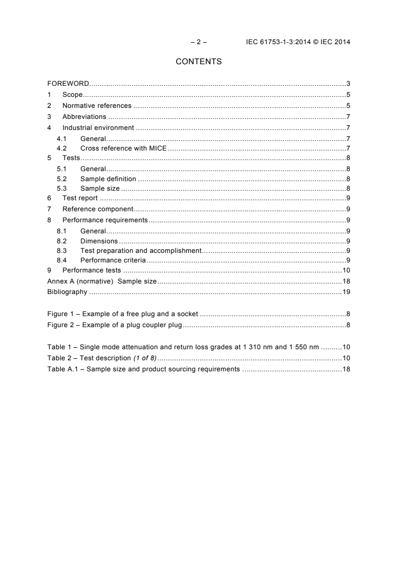
– 2 – IEC 61753-1-3:2014 © IEC 2014
CONTENTS
FOREWORD . 3
1 Scope . 5
2 Normative references . 5
3 Abbreviations . 7
4 Industrial environment . 7
4.1 General . 7
4.2 Cross reference with MICE . 7
5 Tests . 8
5.1 General . 8
5.2 Sample definition . 8
5.3 Sample size . 8
6 Test report . 9
7 Reference component . 9
8 Performance requirements . 9
8.1 General . 9
8.2 Dimensions . 9
8.3 Test preparation and accomplishment . 9
8.4 Performance criteria . 9
9 Performance tests . 10
Annex A (normative) Sample size . 18
Bibliography . 19
Figure 1 – Example of a free plug and a socket . 8
Figure 2 – Example of a plug coupler plug . 8
Table 1 – Single mode attenuation and return loss grades at 1 310 nm and 1 550 nm . 10
Table 2 – Test description (1 of 8) . 10
Table A.1 – Sample size and product sourcing requirements . 18
INTERNATIONAL ELECTROTECHNICAL COMMISSION
____________
FIBRE OPTIC INTERCONNECTING
DEVICES AND PASSIVE COMPONENTS –
PERFORMANCE STANDARD –
Part 1-3: General and guidance for single-mode fibre optic connector
and cable assembly for industrial environment, Category I
FOREWORD
1) The International Electrotechnical Commission (IEC) is a worldwide organization for standardization comprising
all national electrotechnical committees (IEC National Committees). The object of IEC is to promote
international co-operation on all questions concerning standardization in the electrical and electronic fields. To
this end and in addition to other activities, IEC publishes International Standards, Technical Specifications,
Technical Reports, Publicly Available Specifications (PAS) and Guides (hereafter referred to as “IEC
Publication(s)”). Their preparation is entrusted to technical committees; any IEC National Committee interested
in the subject dealt with may participate in this preparatory work. International, governmental and non-
governmental organizations liaising with the IEC also participate in this preparation. IEC collaborates closely
with the International Organization for Standardization (ISO) in accordance with conditions determined by
agreement between the two organizations.
2) The formal decisions or agreements of IEC on technical matters express, as nearly as possible, an international
consensus of opinion on the relevant subjects since each technical committee has representation from all
interested IEC National Committees.
3) IEC Publications have the form of recommendations for international use and are accepted by IEC National
Committees in that sense. While all reasonable efforts are made to ensure that the technical content of IEC
Publications is accurate, IEC cannot be held responsible for the way in which they are used or for any
misinterpretation by any end user.
4) In order to promote international uniformity, IEC National Committees undertake to apply IEC Publications
transparently to the maximum extent possible in their national and regional publications. Any divergence
between any IEC Publication and the corresponding national or regional publication shall be clearly indicated in
the latter.
5) IEC itself does not provide any attestation of conformity. Independent certification bodies provide conformity
assessment services and, in some areas, access to IEC marks of conformity. IEC is not responsible for any
services carried out by independent certification bodies.
6) All users should ensure that they have the latest edition of this publication.
7) No liability shall attach to IEC or its directors, employees, servants or agents including individual experts and
members of its technical committees and IEC National Committees for any personal injury, property damage or
other damage of any nature whatsoever, whether direct or indirect, or for costs (including legal fees) and
expenses arising out of the publication, use of, or reliance upon, this IEC Publication or any other IEC
Publications.
8) Attention is drawn to the Normative references cited in this publication. Use of the referenced publications is
indispensable for the correct application of this publication.
9) Attention is drawn to the possibility that some of the elements of this IEC Publication may be the subject of
patent rights. IEC shall not be held responsible for identifying any or all such patent rights.
International Standard IEC 61753-1-3 has been prepared by subcommittee 86B: Fibre optic
interconnecting devices and passive components, of IEC technical committee 86: Fibre optics.
This first edition cancels and replaces IEC/PAS 61753-1-3 published in 2009. This edition
constitutes a technical revision.
The text of this standard is based on the following documents:
FDIS Report on voting
86B/3752/FDIS 86B/3780/RVD
– 4 – IEC 61753-1-3:2014 © IEC 2014
Full information on the voting for the approval of this standard can be found in the report on
voting indicated in the above table.
This publication has been drafted in accordance with the ISO/IEC Directives, Part 2.
A list of all parts in the IEC 61753 series, published under the general title Fibre optic
interconnecting devices and passive components – Performance standard, can be found on
the IEC website.
The committee has decided that the contents of this publication will remain unchanged until
the stability date indicated on the IEC web site under "http://webstore.iec.ch" in the data
related to the specific publication. At this date, the publication will be
• reconfirmed,
• withdrawn,
• replaced by a revised edition, or
• amended.
A bilingual version of this publication may be issued at a later date.
FIBRE OPTIC INTERCONNECTING
DEVICES AND PASSIVE COMPONENTS –
PERFORMANCE STANDARD –
Part 1-3: General and guidance for single-mode fibre optic connector
and cable assembly for industrial environment, Category I
1 Scope
This part of IEC 61753 defines the minimum initial performance, test and measurement
requirements and severities which a connector or cable assembly with single-mode fibres
needs to satisfy in order to be categorized as meeting IEC Category I (industrial environment).
Category I is an additional environmental category to C, U, O and E already described in
IEC 61753-1. Category I is based on the MICE Table described in ISO/IEC 24702.
The performance tests evaluate the product for two basic acceptance criteria: mechanical
integrity and optical transmission requirements, by simulating the effects of exposure to the
environment in which it will be installed, simulating installation and intervention conditions,
and evaluating specified features of the product.
The defined performance test procedures simulate the situation in a mated condition under
use in an industrial environment. It is not the intention to simulate the situation:
when being mated or demated;
during the assembling of the connector;
during transportation and storage of the connector.
Reliability tests for life time expectations are not covered by this standard.
2 Normative references
The following documents, in whole or in part, are normatively referenced in this document and
are indispensable for its application. For dated references, only the edition cited applies. For
undated references, the latest edition of the referenced document (including any
amendments) applies.
IEC 60068-2-60, Environmental testing – Part 2: Tests – Test Ke: Flowing mixed gas
corrosion test
IEC 60529:1989, Degrees of protection provided by enclosures (IP Code)
IEC 60793-2-50, Optical fibres – Part 2-50: Product specifications – Sectional specification for
class B single-mode fibres
IEC 61300 (all parts), Fibre optic interconnecting devices and passive components – Basic
test and measurement procedures
IEC 61300-2-1, Fibre optic interconnecting devices and passive components – Basic test and
measurement procedures – Part 2-1: Tests – Vibration (sinusoidal)
IEC 61300-2-2, Fibre optic interconnecting devices and passive components – Basic test and
measurement procedures – Part 2-2: Tests – Mating durability
– 6 – IEC 61753-1-3:2014 © IEC 2014
IEC 61300-2-4, Fibre optic interconnecting devices and passive components – Basic test and
measurement procedures – Part 2-4: Tests – Fibre/cable retention
IEC 61300-2-5, Fibre optic interconnecting devices and passive components – Basic test and
measurement procedures – Part 2-5: Tests – Torsion
IEC 61300-2-6, Fibre optic interconnecting devices and passive components – Basic test and
measurement procedures – Part 2-6: Tests – Tensile strength of coupling mechanism
IEC 61300-2-7, Fibre optic interconnecting devices and passive components – Basic test and
measurement procedures – Part 2-7: Tests – Bending moment
IEC 61300-2-9, Fibre optic interconnecting devices and passive components – Basic test and
measurement procedures – Part 2-9: Tests – Shock
IEC 61300-2-10, Fibre optic interconnecting devices and passive components – Basic test
and measurement procedures – Part 2-10: Tests – Crush resistance
IEC 61300-2-12, Fibre optic interconnecting devices and passive components – Basic test
and measurement procedures – Part 2-12: Tests – Impact
IEC 61300-2-22, Fibre optic interconnecting devices and passive components – Basic test
and measurement procedures – Part 2-2: Tests – Mating durability
IEC 61300-2-26, Fibre optic interconnecting devices and passive components – Basic test
and measurement procedures – Part 2-26: Tests – Salt mist
IEC 61300-2-34, Fibre optic interconnecting devices and passive components – Basic test
and measurement procedures – Part 2-34: Tests – Resistance to solvents and contaminating
fluids of interconnecting components and closures
IEC 61300-2-46, Fibre optic interconnecting devices and passive components – Basic test
and measurement procedures – Part 2-46: Tests – Damp heat, cyclic
IEC 61300-3-1, Fibre optic interconnecting devices and passive components – Basic test and
measurement procedures – Part 3-1: Examinations and measurements – Visual examination
IEC 61300-3-3, Fibre optic interconnecting devices and passive components – Basic test and
measurement procedures – Part 3-3: Examinations and measurements – Active monitoring of
changes in attenuation and return loss
IEC 61300-3-4:2012, Fibre optic interconnecting devices and passive components – Basic
test and measurement procedures – Part 3-4: Examinations and measurements – Attenuation
IEC 61300-3-6, Fibre optic interconnecting devices and passive components – Basic test and
measurement procedures – Part 3-6: Examinations and measurements – Return loss
IEC 61300-3-11, Fibre optic interconnecting devices and passive components – Basic test
and measurement procedures – Part 3-11: Examinations and measurements – Engagement
and separation forces
IEC 61300-3-28, Fibre optic interconnecting devices and passive components – Basic test
and measurement procedures – Part 3-28: Examinations and measurements – Transient loss
IEC 61300-3-34, Fibre optic interconnecting devices and passive components – Basic test
and measurement procedures – Part 3-34: Examinations and measurements – Attenuation of
random mated connectors
IEC 61300-3-35, Fibre optic interconnecting devices and passive components – Basic test
and measurement procedures – Part 3-35: Examinations and measurements – Fibre optic
connector endface visual and automated inspection
IEC 61753-1:2007, Fibre optic interconnecting devices and passive components – Part 1:
General and guidance for performance standards
IEC 61754 (all parts), Fibre optic connector interfaces
IEC 61755 (all parts), Fibre optic connector optical interfaces
IEC 61755-1, Fibre optic connector optical interfaces – Part 1: Optical interfaces for single
mode non-dispersion shifted fibres – General and guidance
IEC 60529, Degrees of protection provided by enclosures (IP Code)
ISO/IEC 24702, Information technology – Generic cabling – Industrial premises
ISO/IEC TR 29106, Information technology – Generic cabling – Introduction to the MICE
environmental classification
3 Abbreviations
For the purposes of this document, the following abbreviations are used.
IL Insertion loss
MICE Mechanical, ingress, climatic and chemical and electromagnetic classification of
the environment
OTDR Optical time domain reflectometry
RL Return loss
4 Industrial environment
4.1 General
Fibre optic components are frequently used in industrial environments like control stations,
power rooms or inside switch cabinets. The environmental conditions such as temperature,
dust, moisture, vibration, chemicals, impact etc. found in industrial deployment, may require
robust and sealed components to protect the optical interfaces from the effects of the
environment.
4.2 Cross reference with MICE
ISO/IEC TR 29106 classifies the environment local to a cabling system in terms of MICE
characteristics. The tests and severities in Clause 9 of this standard are intended to reflect
the M and I environment. The climatic conditions and chemical substances used are
3 3
selected from the C environment. The defined tests and severities are according to
IEC 60068-2-60.
NOTE Only a small subset of the chemical substances from the C environment are used, and these are at
different concentrations.
– 8 – IEC 61753-1-3:2014 © IEC 2014
5 Tests
5.1 General
All test methods are in accordance with the IEC 61300 series as defined in Table A.1.
Each test defines the number of samples to be evaluated as described in Annex A. The
samples used for each test should be composed of randomly selected and previously
unstressed new samples but may also be selected from previously used samples if desired.
The connectors under test shall be terminated onto single-mode fibre per IEC 60793-2-50,
type B1.1, B1.3 or B6, depending upon the design of connector. The connector interface
standard shall meet the dimensions of the IEC 61754 series and the connector optical
interface standard shall meet the relevant requirements of the IEC 61755 series.
Unless otherwise specified, tests should be carried out under standard atmospheric
conditions according to IEC 61300-1. The optical criteria for each test shall be as defined in
Clause 9 (see also notes to Table 1).
5.2 Sample definition
For the purposes of this standard, a sample is a complete set of passive connector
components consisting of a free plug and a socket, as shown in Figure 1, or a plug coupler
plug, as shown in Figure 2. The socket may be mounted in an enclosure. This allows
demountable coupling between pairs of optical fibres.
Products under test shall be mounted and cleaned according to the manufacturer’s
instructions.
Each of the non terminated leads from the socket should be at least 3 m long so that the
splices may be located outside of the environmental test chamber.
Socket
Sealed area
Free plug
IEC 1587/14
Figure 1 – Example of a fr
...
IEC 61753-1-3 ®
Edition 1.0 2014-05
INTERNATIONAL
STANDARD
NORME
INTERNATIONALE
Fibre optic interconnecting devices and passive components – Performance
standard –
Part 1-3: General and guidance for single-mode fibre optic connector and cable
assembly for industrial environment, Category I
Dispositifs d’interconnexion et composants passifs à fibres optiques – Norme
de performance –
Partie 1-3: Généralités et lignes directrices relatives aux connecteurs à fibres
optiques unimodales et aux cordons en environnement industriel, Catégorie I
All rights reserved. Unless otherwise specified, no part of this publication may be reproduced or utilized in any form
or by any means, electronic or mechanical, including photocopying and microfilm, without permission in writing from
either IEC or IEC's member National Committee in the country of the requester. If you have any questions about IEC
copyright or have an enquiry about obtaining additional rights to this publication, please contact the address below or
your local IEC member National Committee for further information.
Droits de reproduction réservés. Sauf indication contraire, aucune partie de cette publication ne peut être reproduite
ni utilisée sous quelque forme que ce soit et par aucun procédé, électronique ou mécanique, y compris la photocopie
et les microfilms, sans l'accord écrit de l'IEC ou du Comité national de l'IEC du pays du demandeur. Si vous avez des
questions sur le copyright de l'IEC ou si vous désirez obtenir des droits supplémentaires sur cette publication, utilisez
les coordonnées ci-après ou contactez le Comité national de l'IEC de votre pays de résidence.
IEC Central Office Tel.: +41 22 919 02 11
3, rue de Varembé Fax: +41 22 919 03 00
CH-1211 Geneva 20 info@iec.ch
Switzerland www.iec.ch
About the IEC
The International Electrotechnical Commission (IEC) is the leading global organization that prepares and publishes
International Standards for all electrical, electronic and related technologies.
About IEC publications
The technical content of IEC publications is kept under constant review by the IEC. Please make sure that you have the
latest edition, a corrigenda or an amendment might have been published.
IEC Catalogue - webstore.iec.ch/catalogue Electropedia - www.electropedia.org
The stand-alone application for consulting the entire The world's leading online dictionary of electronic and
bibliographical information on IEC International Standards, electrical terms containing 20 000 terms and definitions in
Technical Specifications, Technical Reports and other English and French, with equivalent terms in 15 additional
documents. Available for PC, Mac OS, Android Tablets and languages. Also known as the International Electrotechnical
iPad. Vocabulary (IEV) online.
IEC publications search - www.iec.ch/searchpub IEC Glossary - std.iec.ch/glossary
The advanced search enables to find IEC publications by a 65 000 electrotechnical terminology entries in English and
variety of criteria (reference number, text, technical French extracted from the Terms and Definitions clause of
committee,…). It also gives information on projects, replaced IEC publications issued since 2002. Some entries have been
and withdrawn publications. collected from earlier publications of IEC TC 37, 77, 86 and
CISPR.
IEC Just Published - webstore.iec.ch/justpublished
Stay up to date on all new IEC publications. Just Published IEC Customer Service Centre - webstore.iec.ch/csc
details all new publications released. Available online and If you wish to give us your feedback on this publication or
also once a month by email. need further assistance, please contact the Customer Service
Centre: csc@iec.ch.
A propos de l'IEC
La Commission Electrotechnique Internationale (IEC) est la première organisation mondiale qui élabore et publie des
Normes internationales pour tout ce qui a trait à l'électricité, à l'électronique et aux technologies apparentées.
A propos des publications IEC
Le contenu technique des publications IEC est constamment revu. Veuillez vous assurer que vous possédez l’édition la
plus récente, un corrigendum ou amendement peut avoir été publié.
Catalogue IEC - webstore.iec.ch/catalogue Electropedia - www.electropedia.org
Application autonome pour consulter tous les renseignements
Le premier dictionnaire en ligne de termes électroniques et
bibliographiques sur les Normes internationales,
électriques. Il contient 20 000 termes et définitions en anglais
Spécifications techniques, Rapports techniques et autres
et en français, ainsi que les termes équivalents dans 15
documents de l'IEC. Disponible pour PC, Mac OS, tablettes
langues additionnelles. Egalement appelé Vocabulaire
Android et iPad.
Electrotechnique International (IEV) en ligne.
Recherche de publications IEC - www.iec.ch/searchpub
Glossaire IEC - std.iec.ch/glossary
La recherche avancée permet de trouver des publications IEC 65 000 entrées terminologiques électrotechniques, en anglais
en utilisant différents critères (numéro de référence, texte, et en français, extraites des articles Termes et Définitions des
comité d’études,…). Elle donne aussi des informations sur les publications IEC parues depuis 2002. Plus certaines entrées
projets et les publications remplacées ou retirées. antérieures extraites des publications des CE 37, 77, 86 et
CISPR de l'IEC.
IEC Just Published - webstore.iec.ch/justpublished
Service Clients - webstore.iec.ch/csc
Restez informé sur les nouvelles publications IEC. Just
Published détaille les nouvelles publications parues. Si vous désirez nous donner des commentaires sur cette
Disponible en ligne et aussi une fois par mois par email. publication ou si vous avez des questions contactez-nous:
csc@iec.ch.
IEC 61753-1-3 ®
Edition 1.0 2014-05
INTERNATIONAL
STANDARD
NORME
INTERNATIONALE
Fibre optic interconnecting devices and passive components – Performance
standard –
Part 1-3: General and guidance for single-mode fibre optic connector and cable
assembly for industrial environment, Category I
Dispositifs d’interconnexion et composants passifs à fibres optiques – Norme
de performance –
Partie 1-3: Généralités et lignes directrices relatives aux connecteurs à fibres
optiques unimodales et aux cordons en environnement industriel, Catégorie I
INTERNATIONAL
ELECTROTECHNICAL
COMMISSION
COMMISSION
ELECTROTECHNIQUE
INTERNATIONALE
ICS 33.180.20 ISBN 978-2-8322-3144-9
– 2 – IEC 61753-1-3:2014 © IEC 2014
CONTENTS
FOREWORD. 3
1 Scope . 5
2 Normative references . 5
3 Abbreviations . 7
4 Industrial environment . 7
4.1 General . 7
4.2 Cross reference with MICE . 7
5 Tests . 8
5.1 General . 8
5.2 Sample definition . 8
5.3 Sample size . 8
6 Test report . 9
7 Reference component . 9
8 Performance requirements . 9
8.1 General . 9
8.2 Dimensions . 9
8.3 Test preparation and accomplishment . 9
8.4 Performance criteria . 9
9 Performance tests . 10
Annex A (normative) Sample size . 18
Bibliography . 19
Figure 1 – Example of a free plug and a socket . 8
Figure 2 – Example of a plug coupler plug . 8
Table 1 – Single mode attenuation and return loss grades at 1 310 nm and 1 550 nm . 10
Table 2 – Test description (1 of 8) . 10
Table A.1 – Sample size and product sourcing requirements . 18
INTERNATIONAL ELECTROTECHNICAL COMMISSION
____________
FIBRE OPTIC INTERCONNECTING
DEVICES AND PASSIVE COMPONENTS –
PERFORMANCE STANDARD –
Part 1-3: General and guidance for single-mode fibre optic connector
and cable assembly for industrial environment, Category I
FOREWORD
1) The International Electrotechnical Commission (IEC) is a worldwide organization for standardization comprising
all national electrotechnical committees (IEC National Committees). The object of IEC is to promote
international co-operation on all questions concerning standardization in the electrical and electronic fields. To
this end and in addition to other activities, IEC publishes International Standards, Technical Specifications,
Technical Reports, Publicly Available Specifications (PAS) and Guides (hereafter referred to as “IEC
Publication(s)”). Their preparation is entrusted to technical committees; any IEC National Committee interested
in the subject dealt with may participate in this preparatory work. International, governmental and non-
governmental organizations liaising with the IEC also participate in this preparation. IEC collaborates closely
with the International Organization for Standardization (ISO) in accordance with conditions determined by
agreement between the two organizations.
2) The formal decisions or agreements of IEC on technical matters express, as nearly as possible, an international
consensus of opinion on the relevant subjects since each technical committee has representation from all
interested IEC National Committees.
3) IEC Publications have the form of recommendations for international use and are accepted by IEC National
Committees in that sense. While all reasonable efforts are made to ensure that the technical content of IEC
Publications is accurate, IEC cannot be held responsible for the way in which they are used or for any
misinterpretation by any end user.
4) In order to promote international uniformity, IEC National Committees undertake to apply IEC Publications
transparently to the maximum extent possible in their national and regional publications. Any divergence
between any IEC Publication and the corresponding national or regional publication shall be clearly indicated in
the latter.
5) IEC itself does not provide any attestation of conformity. Independent certification bodies provide conformity
assessment services and, in some areas, access to IEC marks of conformity. IEC is not responsible for any
services carried out by independent certification bodies.
6) All users should ensure that they have the latest edition of this publication.
7) No liability shall attach to IEC or its directors, employees, servants or agents including individual experts and
members of its technical committees and IEC National Committees for any personal injury, property damage or
other damage of any nature whatsoever, whether direct or indirect, or for costs (including legal fees) and
expenses arising out of the publication, use of, or reliance upon, this IEC Publication or any other IEC
Publications.
8) Attention is drawn to the Normative references cited in this publication. Use of the referenced publications is
indispensable for the correct application of this publication.
9) Attention is drawn to the possibility that some of the elements of this IEC Publication may be the subject of
patent rights. IEC shall not be held responsible for identifying any or all such patent rights.
International Standard IEC 61753-1-3 has been prepared by subcommittee 86B: Fibre optic
interconnecting devices and passive components, of IEC technical committee 86: Fibre optics.
This first edition cancels and replaces IEC/PAS 61753-1-3 published in 2009. This edition
constitutes a technical revision.
This bilingual version (2016-02) corresponds to the monolingual English version, published in
2014-05.
The text of this standard is based on the following documents:
– 4 – IEC 61753-1-3:2014 © IEC 2014
FDIS Report on voting
86B/3752/FDIS 86B/3780/RVD
Full information on the voting for the approval of this standard can be found in the report on
voting indicated in the above table.
The French version of this standard has not been voted upon.
This publication has been drafted in accordance with the ISO/IEC Directives, Part 2.
A list of all parts in the IEC 61753 series, published under the general title Fibre optic
interconnecting devices and passive components – Performance standard, can be found on
the IEC website.
The committee has decided that the contents of this publication will remain unchanged until
the stability date indicated on the IEC web site under "http://webstore.iec.ch" in the data
related to the specific publication. At this date, the publication will be
• reconfirmed,
• withdrawn,
• replaced by a revised edition, or
• amended.
FIBRE OPTIC INTERCONNECTING
DEVICES AND PASSIVE COMPONENTS –
PERFORMANCE STANDARD –
Part 1-3: General and guidance for single-mode fibre optic connector
and cable assembly for industrial environment, Category I
1 Scope
This part of IEC 61753 defines the minimum initial performance, test and measurement
requirements and severities which a connector or cable assembly with single-mode fibres
needs to satisfy in order to be categorized as meeting IEC Category I (industrial environment).
Category I is an additional environmental category to C, U, O and E already described in
IEC 61753-1. Category I is based on the MICE Table described in ISO/IEC 24702.
The performance tests evaluate the product for two basic acceptance criteria: mechanical
integrity and optical transmission requirements, by simulating the effects of exposure to the
environment in which it will be installed, simulating installation and intervention conditions,
and evaluating specified features of the product.
The defined performance test procedures simulate the situation in a mated condition under
use in an industrial environment. It is not the intention to simulate the situation:
when being mated or demated;
during the assembling of the connector;
during transportation and storage of the connector.
Reliability tests for life time expectations are not covered by this standard.
2 Normative references
The following documents, in whole or in part, are normatively referenced in this document and
are indispensable for its application. For dated references, only the edition cited applies. For
undated references, the latest edition of the referenced document (including any
amendments) applies.
IEC 60068-2-60, Environmental testing – Part 2: Tests – Test Ke: Flowing mixed gas
corrosion test
IEC 60529:1989, Degrees of protection provided by enclosures (IP Code)
IEC 60793-2-50, Optical fibres – Part 2-50: Product specifications – Sectional specification for
class B single-mode fibres
IEC 61300 (all parts), Fibre optic interconnecting devices and passive components – Basic
test and measurement procedures
IEC 61300-2-1, Fibre optic interconnecting devices and passive components – Basic test and
measurement procedures – Part 2-1: Tests – Vibration (sinusoidal)
IEC 61300-2-2, Fibre optic interconnecting devices and passive components – Basic test and
measurement procedures – Part 2-2: Tests – Mating durability
– 6 – IEC 61753-1-3:2014 © IEC 2014
IEC 61300-2-4, Fibre optic interconnecting devices and passive components – Basic test and
measurement procedures – Part 2-4: Tests – Fibre/cable retention
IEC 61300-2-5, Fibre optic interconnecting devices and passive components – Basic test and
measurement procedures – Part 2-5: Tests – Torsion
IEC 61300-2-6, Fibre optic interconnecting devices and passive components – Basic test and
measurement procedures – Part 2-6: Tests – Tensile strength of coupling mechanism
IEC 61300-2-7, Fibre optic interconnecting devices and passive components – Basic test and
measurement procedures – Part 2-7: Tests – Bending moment
IEC 61300-2-9, Fibre optic interconnecting devices and passive components – Basic test and
measurement procedures – Part 2-9: Tests – Shock
IEC 61300-2-10, Fibre optic interconnecting devices and passive components – Basic test
and measurement procedures – Part 2-10: Tests – Crush resistance
IEC 61300-2-12, Fibre optic interconnecting devices and passive components – Basic test
and measurement procedures – Part 2-12: Tests – Impact
IEC 61300-2-22, Fibre optic interconnecting devices and passive components – Basic test
and measurement procedures – Part 2-2: Tests – Mating durability
IEC 61300-2-26, Fibre optic interconnecting devices and passive components – Basic test
and measurement procedures – Part 2-26: Tests – Salt mist
IEC 61300-2-34, Fibre optic interconnecting devices and passive components – Basic test
and measurement procedures – Part 2-34: Tests – Resistance to solvents and contaminating
fluids of interconnecting components and closures
IEC 61300-2-46, Fibre optic interconnecting devices and passive components – Basic test
and measurement procedures – Part 2-46: Tests – Damp heat, cyclic
IEC 61300-3-1, Fibre optic interconnecting devices and passive components – Basic test and
measurement procedures – Part 3-1: Examinations and measurements – Visual examination
IEC 61300-3-3, Fibre optic interconnecting devices and passive components – Basic test and
measurement procedures – Part 3-3: Examinations and measurements – Active monitoring of
changes in attenuation and return loss
IEC 61300-3-4:2012, Fibre optic interconnecting devices and passive components – Basic
test and measurement procedures – Part 3-4: Examinations and measurements – Attenuation
IEC 61300-3-6, Fibre optic interconnecting devices and passive components – Basic test and
measurement procedures – Part 3-6: Examinations and measurements – Return loss
IEC 61300-3-11, Fibre optic interconnecting devices and passive components – Basic test
and measurement procedures – Part 3-11: Examinations and measurements – Engagement
and separation forces
IEC 61300-3-28, Fibre optic interconnecting devices and passive components – Basic test
and measurement procedures – Part 3-28: Examinations and measurements – Transient loss
IEC 61300-3-34, Fibre optic interconnecting devices and passive components – Basic test
and measurement procedures – Part 3-34: Examinations and measurements – Attenuation of
random mated connectors
IEC 61300-3-35, Fibre optic interconnecting devices and passive components – Basic test
and measurement procedures – Part 3-35: Examinations and measurements – Fibre optic
connector endface visual and automated inspection
IEC 61753-1:2007, Fibre optic interconnecting devices and passive components – Part 1:
General and guidance for performance standards
IEC 61754 (all parts), Fibre optic connector interfaces
IEC 61755 (all parts), Fibre optic connector optical interfaces
IEC 61755-1, Fibre optic connector optical interfaces – Part 1: Optical interfaces for single
mode non-dispersion shifted fibres – General and guidance
IEC 60529, Degrees of protection provided by enclosures (IP Code)
ISO/IEC 24702, Information technology – Generic cabling – Industrial premises
ISO/IEC TR 29106, Information technology – Generic cabling – Introduction to the MICE
environmental classification
3 Abbreviations
For the purposes of this document, the following abbreviations are used.
IL Insertion loss
MICE Mechanical, ingress, climatic and chemical and electromagnetic classification of
the environment
OTDR Optical time domain reflectometry
RL Return loss
4 Industrial environment
4.1 General
Fibre optic components are frequently used in industrial environments like control stations,
power rooms or inside switch cabinets. The environmental conditions such as temperature,
dust, moisture, vibration, chemicals, impact etc. found in industrial deployment, may require
robust and sealed components to protect the optical interfaces from the effects of the
environment.
4.2 Cross reference with MICE
ISO/IEC TR 29106 classifies the environment local to a cabling system in terms of MICE
characteristics. The tests and severities in Clause 9 of this standard are intended to reflect
the M and I environment. The climatic conditions and chemical substances used are
3 3
selected from the C environment. The defined tests and severities are according to
IEC 60068-2-60.
NOTE Only a small subset of the chemical substances from the C environment are used, and these are at
different concentrations.
– 8 – IEC 61753-1-3:2014 © IEC 2014
5 Tests
5.1 General
All test methods are in accordance with the IEC 61300 series as defined in Table A.1.
Each test defines the number of samples to be evaluated as described in Annex A. The
samples used for each test should be composed of randomly selected and previously
unstressed new samples but may also be selected from previously used samples if desired.
The connectors under test shall be terminated onto single-mode fibre per IEC 60793-2-50,
type B1.1, B1.3 or B6, depending upon the design of connector. The connector interface
standard shall meet the dimensions of the IEC 61754 series and the connector optical
interface standard shall meet the relevant requirements of the IEC 61755 series.
Unless otherwise specified, tests should be carried out under standard atmospheric
conditions according to IEC 61300-1. The optical criteria for each test shall be as defined in
Clause 9 (see also notes to Table 1).
5.2 Sample definition
For the purposes of this standard, a sample is a complete set of passive connector
components consisting of a free plug and a socket, as shown in Figure 1, or a plug coupler
plug, as shown in Figure 2. The socket may be mounted in an enclosure. This allows
demountable coupling between pairs of optical fibres.
Products under test shall be mounted and cleaned according to the manufacturer’s
instructions.
Each of the non terminated leads from the socket should be at least 3 m long so that the
splices may be located outside of the environmental test chamber.
Socket
Sealed area
Free plug
IEC 1587/14
Figure 1 – Example of a free plug and a socket
Coupler
Sealed area
Plug
Free plug
IEC 1588/14
Figure 2 – Example of a plug coupler plug
5.3 Sample size
Default sample sizes for the tests are defined in Annex A.
As a minimum requirement and if not otherwise mentioned, the tests can be run individually
as defined in Annex A.
Samples for the attenuation test shall be randomly selected and randomly mated as new
products. Samples for the return loss test are the same plugs as those selected and mated for
the attenuation test. Samples for subsequent tests may be randomly selected and randomly
mated as new products or they may be the same plugs. However, samples are reused at the
manufacturer’s own risk. In the event that this re-use causes a failure, the test may be re-run
with new samples.
6 Test report
Fully documented test reports and supporting evidence shall be prepared and available for
inspection to show that the tests have been carried out and the results are satisfactory; the
requested performance (see Table 1 for the grades) should be defined before starting the
tests.
7 Reference component
No reference components are required to perform the tests in this standard.
8 Performance requirements
8.1 General
The minimum protection level shall be IP x5 and /or IP x7 for immersion and IP 6x for dust, so
the resulting level will be IP 65 and /or IP 67. The protection level of the connector according
to IEC 60529 shall be determined before performing the tests.
8.2 Dimensions
Dimensions shall comply with the appropriate IEC interface standard as defined in the
IEC 61754 series.
8.3 Test preparation and accomplishment
Before the tests are made, the sample shall be preconditioned under standard atmospheric
conditions for testing as specified in IEC 61300-1 for a period of 2 h.
When mounting is required in a test, the adaptors shall be rigidly mounted on a specified
accessory using the specified connection methods, fixing devices and panel cut-outs.
The combination of connectors shall be maintained during the complete test sequence,
normally without un-mating the sample. When un-mating is required in a test, the end faces of
the sample shall be cleaned according to the manufacturer’s instructions.
8.4 Performance criteria
Before starting the test the following criteria shall be defined:
a) all performed tests according to the chosen performance category and performance
requirements shall be passed with all tested samples;
b) the connector end face shall comply with the end face geometry requirements of the
applicable optical interface standard as defined in the IEC 61755-3 series;
c) the optical performance levels shall meet the requirements of the designated grade as
defined in Table 1;
– 10 – IEC 61753-1-3:2014 © IEC 2014
d) the mechanical performance shall meet the requirements of the defined protection level
according to IEC 60529;
e) a visual examination of the unmated connectors which would impair its operation shall
show no mechanical damage.
9 Performance tests
The following tests shall be performed:
a) Optical performance requirements as described in Table 1 (see also IEC 61755-1)
Table 1 – Single mode attenuation and return loss grades at 1 310 nm and 1 550 nm
Attenuation Attenuation random mated Monitoring change in attenuation and in
grade IEC 61300-3-34 return loss (multiple path) IEC 61300-3-3
Grade A Not defined yet Not defined yet
Grade B
≤ 0,12 dB mean ∆ Attenuation ≤ 0,2 dB during and after
test for pigtails.
≤ 0,25 dB max. for > 97 % of samples
∆ Attenuation ≤ 0,5 dB during and ≤ 0,4 dB
after test for patchcords
Grade C ≤ 0,25 dB mean ∆ Attenuation ≤ 0,2 dB during and after
≤ 0,50 dB max. for > 97 % of samples test for pigtails.
∆ Attenuation ≤ 0,5 dB during and ≤ 0,4 dB
after test for patchcords
Grade D
≤ 0,50 dB mean ∆ Attenuation ≤ 0,2 dB during and after
test for pigtails.
≤ 1,0 dB max. for > 97 % of samples
∆ Attenuation ≤ 0,5 dB during and ≤ 0,4 dB
after test for patchcords
Grade 1 RL ≥ 60 dB (mated) and ≥ 55 dB (unmated)
≥ 60 dB (mated) and ≥ 55 dB (unmated)
during and after test
Grade 2 ≥ 45 dB RL ≥ 45 dB during and after test
Grade 3 ≥ 35 dB RL ≥ 35 dB during and after test
Grade 4 ≥ 26 dB RL ≥ 26 dB during and after test
NOTE 1 Table 1 is taken from Table A.12 of IEC 61753-1:2007.
NOTE 2 For Grade 1 performance level (APC-version), the RL values depend upon the connecting situation:
Minimum ≥ 60 dB (mated) and ≥ 55 dB (unmated), during and after test.
b) Required tests and severities, reflecting an industrial environment, as described in Table 2.
Table 2 – Test description (1 of 8)
Test Test Requirements Details
No.
1 Visual inspection The connector plugs and IEC 61300-3-1, IEC 61300-3-11 and
adaptors or sockts shall be IEC 61300-3-35
inspected for damage that
might impair the performance.
Distortion of any mechanical
part or damage to the end
faces or service-affecting
damage constitutes a failure
Table 2 (2 of 8)
Test Test Requirements Details
No.
2 Attenuation See Table 1 for the IEC 61300-3-34, method 1.
requirements for the different
Random mate, Test wavelengths:
performance levels
IEC 61300-3-34 1 310 nm ± 20 nm and 1 550 nm ± 20 nm
(source condition S5 and S6, source
See also Annex A
condition is in accordance with Table 1 in
IEC 61300-3-4:2012).
Launch mode conditions:
only the fundamental mode shall propagate
at the connector interface and at the
detector.
Sample shall be optically functioning.
Preconditioning procedure: clean plug and
adapter according to manufacturer’s
instructions
3 Return loss See Table 1 for the Test wavelengths:
(IEC 61300-3-6, requirements for the different 1 310 nm ± 20 nm and 1 550 nm ± 20 nm.
method 1 or 2) performance levels
Launch fibre length: L > 2 m.
Random mate
Source stability: ± 0,20 dB over the
See also Annex A
measuring period or at least 1 h.
Detector linearity: within 5 % of the power
levels to be measured.
Directivity: > 65 dB.
Sample shall be optically functioning.
Preconditioning procedure:
clean plug and adaptor according to
manufacturer’s instructions.
Alternative method: IEC 61300-3-6,
Method OTDR
Launch fibre length:
L1 ≥ 500 m, L2 ≥ 6 m, L3 ≥ 6 m
Pulse duration: ≤ 10 ns.
Sample shall be optically functioning.
Preconditioning procedure: clean plug and
adaptor according to manufacturer’s
instructions
4 Impact See Table 1 for the IEC 61300-2-12, method A
requirements for the different
Test wavelengths:
performance levels.
1 550 nm ± 20 nm.
The sample shall not have any
Drop height: 1,5 m
mechanical damage and shall
be inspected as per test 1
Number of drops: 5 per each location.
5 times each rotated 90°.
Sampling rate: Initially and after the last
drop.
Sample shall be unmated during drop
cycles. Dust cap fitted.
Preconditioning procedure: clean plug and
adaptor according to manufacturer’s
instructions. Place a dust cap over the
ferrule to protect the fibre end face.
Recovery procedure: the connector may be
cleaned after each drop before
measurement
– 12 – IEC 61753-1-3:2014 © IEC 2014
Table 2 (3 of 8)
Test Test Requirements Details
No.
5 Fibre cable retention During test IEC 61300-2-4
∆ Attenuation: ≤ 0,2 dB. Test wavelengths:
1 550 nm ± 20 nm
See Table 1 for the
requirements for the different Magnitude and rate of application of the load
performance levels. for reinforced cables: 100 N ± 2 N at 5 N/s.
The sample shall not have any
The connector shall be rigidly mounted such
mechanical damage and shall
that the load is applied to the cable retention
be inspected as per test 1
mechanism and not to the coupling
mechanism.
Duration for reinforced cables: 120 s.
Magnitude and rate of application of the load
for secondary coated fibres: 5,0 N ± 0,5 N at
5 N/s.
Duration for buffered fibres: 60 s.
Magnitude and rate of application of the load
for primary coated fibres:
2,0 N ± 0,5 N at 5 N/s.
Point of application of tensile load: 0,3 m
from the end face of the connector.
Sampling rate: Initially and after the load
has reached its maximum level and been
maintained for a minimum of 30 s.
Sample shall be optically functioning.
Preconditioning procedure: clean plug and
adaptor according to manufacturer’s
instructions
6 Cable nutation During test: IEC 61300-2-35 [2]
∆ Attenuation: Test wavelengths: 1 550 nm ± 20 nm.
≤ 0,5 dB
Number of cycles:100 for each plug.
See Table 1 for the
Force: 10 N.
requirements for the different
performance levels.
Rotation angle: 360°.
The sample shall not have any
Sampling rate: continuously according to
mechanical damage and shall
IEC 61300-3-28
be inspected as per test 1
Point of application of the load: 0,2 m from
rear of plug body.
Sample shall be mated during nutation
cycles.
Preconditioning procedure: clean plug and
adaptor according to manufacturer’s
instructions.
Recovery procedure: the connector may be
cleaned after each cycle before
measurement
Table 2 (4 of 8)
Test Test Requirements Details
No.
7 Mating durability During test: IEC 61300-2-2
∆ Attenuation: ≤ 0,2 dB Test wavelengths: 1 550 nm ± 20 nm.
See Table 1 for the Coupling mechanism to be cycled:
requirements for the different plug-adaptor.
performance levels.
Cycling rate: not less than 3 s between each
The sample shall not have any engagement and separation.
mechanical damage and shall
Number of cycles: 500 minimum (only one
be inspected as per test 1
industrial plug is subjected to successive
engagement and separation).
Sample shall be optically functioning.
Preconditioning procedure: clean plug and
adaptor according to manufacturer’s
instructions.
Recovery procedure: the mechanical and
optical alignment parts of the sample may
be cleaned according to manufacturer's
instructions up to 2 times after the final
mating cycle.
In the event that the attenuation exceeds the
allowable limit, the connector may be
cleaned as necessary as, but not more than
25 times during the course of the test. (The
measurements at which the cleaning takes
place shall be discounted from the test
results)
8 Durability by water No water inside the connector. IEC 60529
immersion
See Table 1 for the IP x7, with 30 min at 1 m, below the surface
requirements for the different of water (IP67)
performance levels
and
IPx5 intermittent jet, 12,5 l/min, 6,3 mm,
> 2,5 mm distance, duration 30 min.
25 °C ± 2 °C
Preconditioning procedure: Clean plug and
adaptor according to manufacturer’s
instructions.
Recovery procedure: 2 h at normal ambient
conditions
9 Strength of coupling With IL/RL monitoring: IEC 61300-2-6
mechanism
∆ Attenuation: ≤ 0,2 dB.
Test wavelengths: 1 550 nm ± 20 nm
See Table 1 for the
Magnitude and rate of application of the
requirements for the different
(See NOTE 1)
load: 60 N ± 1 N at 2 N/s
performance levels
Duration: 60 s.
Point of application of the load: 0,3 m from
rear of plug.
Sample shall be optically functioning.
Sampling rate: Initially and after the load
has reached its maximum level and been
maintained for at least 30 s.
Preconditioning procedure:
clean plug and adaptor according to
manufacturer’s instructions. Place a dust
cap over the ferrule to protect the fibre end
face.
Recovery procedure:
5 min recovery period
– 14 – IEC 61753-1-3:2014 © IEC 2014
Table 2 (5 of 8)
Test Test Requirements Details
No.
10 Vibration During IEC 61300-2-1
(sinusoidal)
∆ Attenuation: ≤ 0,2 dB Test wavelength: 1 550 nm ± 20 nm.
See Table 1 for the Displacement 15 mm, 2-9 Hz.
requirements for the different
Acceleration 5 g, 9 Hz to 200 Hz.
performance levels.
Change in frequency: 1 oct/min
The sample shall not have any
mechanical damage and shall
Number of axes: 3 orthogonal
be inspected as per test 1
Number of sweeps per axis: 15
Additionally transient monitoring according
to IEC 61300-3-28.
Method of mounting: an adaptor shall be
mounted rigidly to the mounting fixture.
Sample shall be optically functioning.
Preconditioning procedure: clean plug and
adaptor according to manufacturer’s
instructions.
The connector samples may not be
uncoupled or cleaned anytime during the
test
11 Shock During IEC 61300-2-9
∆ Attenuation: ≤ 0,2 dB Test wavelength: 1 550 nm ± 20 nm.
See Table 1 for the 250 m/s , 6ms duration, 5 shocks in each of
requirements for the different the 6 directions.
performance levels.
Additionally. transient monitoring according
The sample shall not have any to IEC 61300-3-28.
mechanical damage and shall
Sampling rate: before, during and after
be inspected as per test 1
shock. Measurements shall be made after
the load has been maintained at its
maximum level for at least 3 s.
Method of mounting: an adaptor shall be
mounted rigidly to the mounting fixture.
Sample shall be optically functioning.
Preconditioning procedure: clean plug and
adaptor according to manufacturer’s
instructions.
The connector samples may not be
uncoupled or cleaned anytime during the
test
Table 2 (6 of 8)
Test Test Requirements Details
No.
12 Torsion During IEC 61300-2-5
∆ Attenuation: ≤ 0,2 dB Test wavelength: 1 550 nm ± 20 nm.
See Table 1 for the
Cycles: 25 (± 180°)
requirements for the different
Force: 10 N at 300 mm from rear of plug
performance levels.
body, at 1 N/s
The sample shall not have any
Sampling rate: before, during and after
mechanical damage and shall
torsion.
be inspected as per test 1
Method of mounting: an adaptor shall be
mounted rigidly to the mounting fixture.
Sample shall be optically functioning.
Preconditioning procedure: Clean plug and
adaptor according to manufacturer’s
instructions.
The connector samples may not be
uncoupled or cleaned anytime during the
test
13 Bending moment During IEC 61300-2-7
∆ Attenuation: ≤ 0,2 dB Test wavelengths: 1 550 nm ± 20 nm.
See Table 1 for the Force 10 N.
requirements for the different
Point of application of bending load: the end
performance levels.
of the connector plug with the moment being
The sample shall not have any about the centre of the adaptor.
mechanical damage and shall
The load shall be applied in 2 perpendicular
be inspected as per test 1
axes with reference to the connector
latching orientation, 55 mm from the outer
front surface of the adaptor.
30 s per axis.
Sampling rate: initially and after the load
has reached its maximum level and been
maintained for a minimum of 30 s.
Sample shall be optically functioning.
Preconditioning procedure: clean plug and
adaptor according to manufacturer’s
instructions. Place a dust cap over the
ferrule to protect the fibre end face
14 Dust No dust inside. IEC 60529:1989
See Table 1 for the IP 6x, Test 6 (Table VII).
requirements for the different
Sample not optically functioning.
performance levels
Testing only in a mated condition.
Particle size: 150 um, talc powder, 10 min.
duration.
Concentration: 10,6 g/m
15 Industrial atmosphere After test: IEC 60068-2-60, method 1
-6
As described in test 1, Visual
Concentration of H2S: 10 × 10
inspection
-6
Concentration of SO2: 5 × 10
See Table 1 for the
Time of exposure: 96 h.
requirements for the different
performance levels. Maximum allowed duration of stabilization
and adjustment is 24 h before the test
The sample shall not have any
mechanical damage and shall
be inspected as per test 1
– 16 – IEC 61753-1-3:2014 © IEC 2014
Table 2 (7 of 8)
Test Test Requirements Details
No.
(see NOTE 2)
16 Change of temperature During IEC 61300-2-22
∆ Attenuation: ≤ 0,2 dB Test wavelength: 1 550 nm ± 20 nm.
See Table 1 for the
High temperature: +70 °C ± 2 °C.
requirements for the different
Low temperature: –40 °C ± 2 °C.
performance levels
Duration at each dwell temperature: 4 h.
Rate of change: 3 °C/min.
Number of cycles: 20.
Length of the cable on each side of the
connector inside the chamber: 1,5 m
minimum.
Sample shall be optically functioning.
Sampling rate: initially at room ambient,
after 30 min during each dwell
(measurements to be completed during
dwell) and at the end of the test at room
ambient.
Preconditioning procedure: before test,
samples shall be maintained in room
temperature condition for 2 h.
Recovery procedure: after the test, samples
shall be maintained in room temperature
condition for 2 h.
The connector samples may not be
uncoupled or cleaned anytime during the
test
17 Damp heat cyclic During IEC 61300-2-46
Minimum temperature: 25 °C.
∆ Attenuation: ≤ 0,2dB
Maximum temperature: 55 °C.
See Table 1 for the
requirements for the different
Humidity: 90 %, no condensing.
performance levels.
6 cycles, 24 h per cycle.
The sample shall not have any
mechanical damage and shall
Sampling rate: initially at room ambient,
be inspected as per test 1
after 30 min during each dwell
(measurements to be completed during
dwell) and at the end of the test at room
ambient.
Preconditioning procedure: before test,
samples shall be maintained in room
temperature condition for 2 h.
Recovery procedure: after test, samples
shall be maintained in room temperature
condition for 2 h.
The connector samples may not be
uncoupled or cleaned anytime during the
test
Table 2 (8 of 8)
Test Test Requirements Details
No.
18 Salt mist See Table 1 for the IEC 61300-2-26
requirements for the different
Salt solution 5 % NaCl.
performance levels.
pH 6,5 – 7,2.
∆ Attenuation: ≤ 0,2dB
Temperature + 35 °C.
Before and after test.
96 h.
The sample shall not have any
mechanical damage and shall
Sample not optically functioning .
be inspected as per test 1
Preconditioning procedure: clean plug and
adaptor according to manufacturer’s
instructions.
The connector samples may not be
uncoupled or cleaned anytime during the
test
19 Resistance to solvents See Table 1 for the IEC 61300-2-34
and contaminating requirements for the different
-6
NaCl 0,3 ×10 at 30 °C
fluids performance levels.
-6
Mineral oil 0,5 ×10 at 70 °C
∆ Attenuation: ≤ 0,2dB.
-6
Soap 50 000 ×10 at 30 °C
Before and after.
24 h
The sample shall not have any
mechanical damage and shall
Sample not optically functioning.
be inspected as per test 1
Preconditioning procedure: clean plug and
adaptor according to manufacturer’s
instructions.
The connector samples may not be
uncoupled or cleaned anytime during the
test
20 Crush resistance See Table 1 for the IEC 61300-2-10
requirements for the different
2 200 N ± 50 N
performance levels.
Pad 50 mm by 50 mm
∆ Attenuation: ≤ 0,2dB.
Centre of housing at 0° and 90° along the
Before and after.
longitudinal axis.
The sample shall not have any
60 s per location.
mechanical damage and shall
be inspected as per test 1
Sample optically functioning.
Sampling rate: before, during (continuous)
and after the test.
...