


IEC 62128-2:2013
(Main)Railway applications - Fixed installations - Electrical safety, earthing and the return circuit - Part 2: Provisions against the effects of stray currents caused by d.c. traction systems
Railway applications - Fixed installations - Electrical safety, earthing and the return circuit - Part 2: Provisions against the effects of stray currents caused by d.c. traction systems
IEC 62128-2:2013 specifies requirements for protective provisions against the effects of stray currents, which result from the operation of d.c. traction systems. This standard applies to all metallic fixed installations which form part of the traction system, and also to any other metallic components located in any position in the earth, which can carry stray currents resulting from the operation of the railway system. This standard applies to all new d.c. lines and to all major revisions to existing d.c. lines. The main technical changes with regard to the previous edition are the restructuring of all clauses.
Applications ferroviaires - Installations fixes - Sécurité électrique, mise à la terre et circuit de retour - Partie 2: Mesures de protection contre les effets des courants vagabonds issus de la traction électrique à courant continu
La CEI 62128-2:2013 spécifie les exigences relatives aux mesures de protection contre les effets des courants vagabonds issus du fonctionnement normal des réseaux de traction à courant continu. La présente norme s'applique à toutes les installations fixes métalliques qui font partie du réseau de traction ainsi qu'à tout autre composant métallique se trouvant dans le sol quelle que soit sa position et qui peut transporter des courants vagabonds issus de l'exploitation du réseau ferroviaire. Cette norme s'applique à l'ensemble des lignes nouvelles en courant continu et aux rénovations majeures apportées aux lignes existantes. Les principales modifications techniques par rapport à l'édition précédente consistent en la restructuration de tous les articles.
General Information
- Status
- Published
- Publication Date
- 15-Sep-2013
- Technical Committee
- TC 9 - Electrical equipment and systems for railways
- Drafting Committee
- WG 49 - TC 9/WG 49
- Current Stage
- PPUB - Publication issued
- Start Date
- 16-Sep-2013
- Completion Date
- 15-Sep-2013
Relations
- Effective Date
- 05-Sep-2023
Overview
IEC 62128-2:2013 - "Railway applications - Fixed installations - Electrical safety, earthing and the return circuit - Part 2: Provisions against the effects of stray currents caused by d.c. traction systems" - is an internationally recognized standard published by the International Electrotechnical Commission (IEC). This standard establishes essential requirements to prevent and control the adverse effects of stray currents generated by direct current (d.c.) traction systems in railway infrastructure.
Stray currents can lead to significant corrosion and operational risks in both railway assets and nearby metallic structures. IEC 62128-2:2013 outlines protective measures for metallic fixed installations forming part of the traction system as well as other metallic components in the ground that could carry stray currents. The scope primarily covers new d.c. railway lines and major modifications to existing lines and provides principles that are also valuable for evaluating and upgrading existing installations.
Key Topics
- Stray Current Hazards: Identification and assessment of hazards associated with stray currents, such as corrosion of metallic structures and safety risks from overheating, arcing, or fire.
- Assessment and Acceptance Criteria: Parameters for evaluating stray current impact, including conductance per length of tracks, rail-to-earth potentials, and acceptable thresholds for safety and asset protection.
- Design Provisions: Recommendations for the design and installation of return circuits, return conductors and cables, electrical separation practices, cross-bonding, and insulation methods.
- Protection of Structures: Specific provisions for protecting tunnels, bridges, viaducts, reinforced concrete, and adjacent metallic installations from stray current damage.
- Testing and Monitoring: Guidelines for testing, validating, and monitoring stray current controls, including continuous supervision and periodic assessment of rail potentials and system insulation.
- System Integration: Considerations for integration with non-traction electrical systems, substations, and scenarios such as tram and trolleybus shared infrastructures.
Applications
IEC 62128-2:2013 is relevant to a variety of rail and mass transit applications that utilize d.c. traction systems, including:
- Mainline railways
- Tramways and light rail systems
- Underground and elevated metro systems
- Mountain railways and trolleybus networks utilizing d.c. traction
- Material transportation systems (excluding underground mine railways, cranes, and similar equipment)
- Infrastructure projects involving major upgrades or extensions to existing d.c.-powered lines
By implementing the provisions of IEC 62128-2:2013, railway infrastructure designers, operators, and maintainers ensure:
- Enhanced electrical safety across all relevant fixed installations
- Prolonged equipment lifespan through effective control of corrosion risks
- Safety for personnel and the public from electrical hazards
- Compliance with international best practices for electrical earthing and return circuits in railway systems
These measures are essential for sustainable operation, reduced maintenance costs, and protection of both railway assets and nearby third-party infrastructure from electrical interference and corrosion.
Related Standards
To ensure holistic compliance and optimal integration, IEC 62128-2:2013 should be referenced alongside other key railway standards, such as:
- IEC 62128-1: Railway applications - Fixed installations - Electrical safety, earthing and the return circuit - Part 1: Protective provisions against electric shock
- IEC 60850: Railway applications - Supply voltages of traction systems
- IEC 62128-3: Railway applications - Fixed installations - Electrical safety, earthing and the return circuit - Part 3: Mutual interaction of a.c. and d.c. traction systems
- EN 50122-2 (for European contexts): Railway applications - Fixed installations - Electrical safety, earthing and the return circuit - Part 2: Provisions against the effects of stray currents caused by d.c. traction systems
- EN 50162: Protection against corrosion by stray current - Criteria and protective measures (European guidance on permissible voltage shifts and corrosion prevention)
IEC 62128-2:2013 plays a vital role in supporting electrical safety, asset protection, and the reliable operation of modern d.c. traction railway systems worldwide.
Buy Documents
IEC 62128-2:2013 - Railway applications - Fixed installations - Electrical safety, earthing and the return circuit - Part 2: Provisions against the effects of stray currents caused by d.c. traction systems Released:9/16/2013
Get Certified
Connect with accredited certification bodies for this standard

IRIS Certification (UNIFE)
International Railway Industry Standard certification.

TÜV SÜD Rail GmbH
TÜV SÜD railway certification services.

Bureau Veritas Railway Certification
Railway and transportation certification.
Sponsored listings
Frequently Asked Questions
IEC 62128-2:2013 is a standard published by the International Electrotechnical Commission (IEC). Its full title is "Railway applications - Fixed installations - Electrical safety, earthing and the return circuit - Part 2: Provisions against the effects of stray currents caused by d.c. traction systems". This standard covers: IEC 62128-2:2013 specifies requirements for protective provisions against the effects of stray currents, which result from the operation of d.c. traction systems. This standard applies to all metallic fixed installations which form part of the traction system, and also to any other metallic components located in any position in the earth, which can carry stray currents resulting from the operation of the railway system. This standard applies to all new d.c. lines and to all major revisions to existing d.c. lines. The main technical changes with regard to the previous edition are the restructuring of all clauses.
IEC 62128-2:2013 specifies requirements for protective provisions against the effects of stray currents, which result from the operation of d.c. traction systems. This standard applies to all metallic fixed installations which form part of the traction system, and also to any other metallic components located in any position in the earth, which can carry stray currents resulting from the operation of the railway system. This standard applies to all new d.c. lines and to all major revisions to existing d.c. lines. The main technical changes with regard to the previous edition are the restructuring of all clauses.
IEC 62128-2:2013 is classified under the following ICS (International Classification for Standards) categories: 45.060.01 - Railway rolling stock in general. The ICS classification helps identify the subject area and facilitates finding related standards.
IEC 62128-2:2013 has the following relationships with other standards: It is inter standard links to IEC 62128-2:2003. Understanding these relationships helps ensure you are using the most current and applicable version of the standard.
IEC 62128-2:2013 is available in PDF format for immediate download after purchase. The document can be added to your cart and obtained through the secure checkout process. Digital delivery ensures instant access to the complete standard document.
Standards Content (Sample)
IEC 62128-2 ®
Edition 2.0 2013-09
INTERNATIONAL
STANDARD
NORME
INTERNATIONALE
Railway applications – Fixed installations – Electrical safety, earthing and the
return circuit –
Part 2: Provisions against the effects of stray currents caused by d.c. traction
systems
Applications ferroviaires – Installations fixes – Sécurité électrique, mise à la
terre et circuit de retour –
Partie 2: Mesures de protection contre les effets des courants vagabonds issus
de la traction électrique à courant continu
All rights reserved. Unless otherwise specified, no part of this publication may be reproduced or utilized in any form
or by any means, electronic or mechanical, including photocopying and microfilm, without permission in writing from
either IEC or IEC's member National Committee in the country of the requester.
If you have any questions about IEC copyright or have an enquiry about obtaining additional rights to this publication,
please contact the address below or your local IEC member National Committee for further information.
Droits de reproduction réservés. Sauf indication contraire, aucune partie de cette publication ne peut être reproduite ni
utilisée sous quelque forme que ce soit et par aucun procédé, électronique ou mécanique, y compris la photocopie et les
microfilms, sans l'accord écrit de la CEI ou du Comité national de la CEI du pays du demandeur.
Si vous avez des questions sur le copyright de la CEI ou si vous désirez obtenir des droits supplémentaires sur cette
publication, utilisez les coordonnées ci-après ou contactez le Comité national de la CEI de votre pays de résidence.
IEC Central Office Tel.: +41 22 919 02 11
3, rue de Varembé Fax: +41 22 919 03 00
CH-1211 Geneva 20 info@iec.ch
Switzerland www.iec.ch
About the IEC
The International Electrotechnical Commission (IEC) is the leading global organization that prepares and publishes
International Standards for all electrical, electronic and related technologies.
About IEC publications
The technical content of IEC publications is kept under constant review by the IEC. Please make sure that you have the
latest edition, a corrigenda or an amendment might have been published.
Useful links:
IEC publications search - www.iec.ch/searchpub Electropedia - www.electropedia.org
The advanced search enables you to find IEC publications The world's leading online dictionary of electronic and
by a variety of criteria (reference number, text, technical electrical terms containing more than 30 000 terms and
committee,…). definitions in English and French, with equivalent terms in
It also gives information on projects, replaced and additional languages. Also known as the International
withdrawn publications. Electrotechnical Vocabulary (IEV) on-line.
IEC Just Published - webstore.iec.ch/justpublished Customer Service Centre - webstore.iec.ch/csc
Stay up to date on all new IEC publications. Just Published If you wish to give us your feedback on this publication
details all new publications released. Available on-line and or need further assistance, please contact the
also once a month by email. Customer Service Centre: csc@iec.ch.
A propos de la CEI
La Commission Electrotechnique Internationale (CEI) est la première organisation mondiale qui élabore et publie des
Normes internationales pour tout ce qui a trait à l'électricité, à l'électronique et aux technologies apparentées.
A propos des publications CEI
Le contenu technique des publications de la CEI est constamment revu. Veuillez vous assurer que vous possédez
l’édition la plus récente, un corrigendum ou amendement peut avoir été publié.
Liens utiles:
Recherche de publications CEI - www.iec.ch/searchpub Electropedia - www.electropedia.org
La recherche avancée vous permet de trouver des Le premier dictionnaire en ligne au monde de termes
publications CEI en utilisant différents critères (numéro de électroniques et électriques. Il contient plus de 30 000
référence, texte, comité d’études,…). termes et définitions en anglais et en français, ainsi que
Elle donne aussi des informations sur les projets et les les termes équivalents dans les langues additionnelles.
publications remplacées ou retirées. Egalement appelé Vocabulaire Electrotechnique
International (VEI) en ligne.
Just Published CEI - webstore.iec.ch/justpublished
Service Clients - webstore.iec.ch/csc
Restez informé sur les nouvelles publications de la CEI.
Just Published détaille les nouvelles publications parues. Si vous désirez nous donner des commentaires sur
Disponible en ligne et aussi une fois par mois par email. cette publication ou si vous avez des questions
contactez-nous: csc@iec.ch.
IEC 62128-2 ®
Edition 2.0 2013-09
INTERNATIONAL
STANDARD
NORME
INTERNATIONALE
Railway applications – Fixed installations – Electrical safety, earthing and the
return circuit –
Part 2: Provisions against the effects of stray currents caused by d.c. traction
systems
Applications ferroviaires – Installations fixes – Sécurité électrique, mise à la
terre et circuit de retour –
Partie 2: Mesures de protection contre les effets des courants vagabonds issus
de la traction électrique à courant continu
INTERNATIONAL
ELECTROTECHNICAL
COMMISSION
COMMISSION
ELECTROTECHNIQUE
PRICE CODE
INTERNATIONALE
CODE PRIX V
ICS 45.060 ISBN 978-2-8891-2000-0
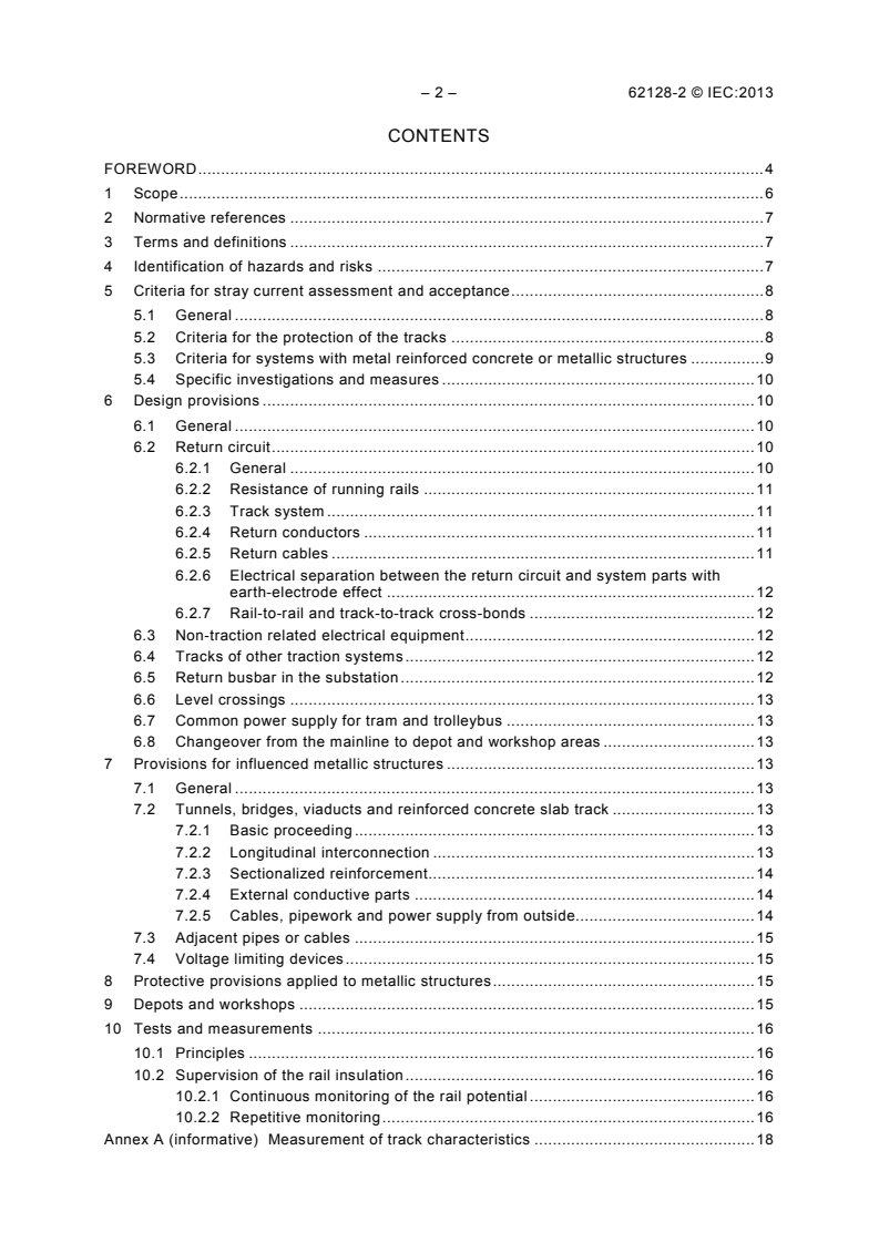
– 2 – 62128-2 © IEC:2013
CONTENTS
FOREWORD . 4
1 Scope . 6
2 Normative references . 7
3 Terms and definitions . 7
4 Identification of hazards and risks . 7
5 Criteria for stray current assessment and acceptance . 8
5.1 General . 8
5.2 Criteria for the protection of the tracks . 8
5.3 Criteria for systems with metal reinforced concrete or metallic structures . 9
5.4 Specific investigations and measures . 10
6 Design provisions . 10
6.1 General . 10
6.2 Return circuit . 10
6.2.1 General . 10
6.2.2 Resistance of running rails . 11
6.2.3 Track system . 11
6.2.4 Return conductors . 11
6.2.5 Return cables . 11
6.2.6 Electrical separation between the return circuit and system parts with
earth-electrode effect . 12
6.2.7 Rail-to-rail and track-to-track cross-bonds . 12
6.3 Non-traction related electrical equipment . 12
6.4 Tracks of other traction systems . 12
6.5 Return busbar in the substation . 12
6.6 Level crossings . 13
6.7 Common power supply for tram and trolleybus . 13
6.8 Changeover from the mainline to depot and workshop areas . 13
7 Provisions for influenced metallic structures . 13
7.1 General . 13
7.2 Tunnels, bridges, viaducts and reinforced concrete slab track . 13
7.2.1 Basic proceeding . 13
7.2.2 Longitudinal interconnection . 13
7.2.3 Sectionalized reinforcement. 14
7.2.4 External conductive parts . 14
7.2.5 Cables, pipework and power supply from outside. 14
7.3 Adjacent pipes or cables . 15
7.4 Voltage limiting devices . 15
8 Protective provisions applied to metallic structures . 15
9 Depots and workshops . 15
10 Tests and measurements . 16
10.1 Principles . 16
10.2 Supervision of the rail insulation . 16
10.2.1 Continuous monitoring of the rail potential . 16
10.2.2 Repetitive monitoring . 16
Annex A (informative) Measurement of track characteristics . 18
62128-2 © IEC:2013 – 3 –
Annex B (informative) Stray current assessment – Rail insulation assessment using
rail potential . 26
Annex C (informative) Estimation of stray current and impact on metal structures . 28
Bibliography . 31
Figure A.1 – Measurement of the rail resistance for a rail of 10 m length . 18
Figure A.2 – Measuring arrangement for the conductance per length G´ between
RS
rails and metal reinforced structure . 19
Figure A.3 – Determination of the conductance per length G´ for track sections
RE
without civil structures . 20
Figure A.4 – Measuring arrangement for the local conductance per length . 21
Figure A.5 – Test of insulating rail joints . 23
Figure A.6 – Test of insulating joints in metal reinforced structures . 24
Figure B.1 – Continuous monitoring of the rail potential . 26
– 4 – 62128-2 © IEC:2013
INTERNATIONAL ELECTROTECHNICAL COMMISSION
____________
RAILWAY APPLICATIONS –
FIXED INSTALLATIONS –
ELECTRICAL SAFETY, EARTHING AND THE RETURN CIRCUIT –
Part 2: Provisions against the effects of stray currents
caused by d.c. traction systems
FOREWORD
1) The International Electrotechnical Commission (IEC) is a worldwide organization for standardization comprising
all national electrotechnical committees (IEC National Committees). The object of IEC is to promote
international co-operation on all questions concerning standardization in the electrical and electronic fields. To
this end and in addition to other activities, IEC publishes International Standards, Technical Specifications,
Technical Reports, Publicly Available Specifications (PAS) and Guides (hereafter referred to as “IEC
Publication(s)”). Their preparation is entrusted to technical committees; any IEC National Committee interested
in the subject dealt with may participate in this preparatory work. International, governmental and non-
governmental organizations liaising with the IEC also participate in this preparation. IEC collaborates closely
with the International Organization for Standardization (ISO) in accordance with conditions determined by
agreement between the two organizations.
2) The formal decisions or agreements of IEC on technical matters express, as nearly as possible, an international
consensus of opinion on the relevant subjects since each technical committee has representation from all
interested IEC National Committees.
3) IEC Publications have the form of recommendations for international use and are accepted by IEC National
Committees in that sense. While all reasonable efforts are made to ensure that the technical content of IEC
Publications is accurate, IEC cannot be held responsible for the way in which they are used or for any
misinterpretation by any end user.
4) In order to promote international uniformity, IEC National Committees undertake to apply IEC Publications
transparently to the maximum extent possible in their national and regional publications. Any divergence
between any IEC Publication and the corresponding national or regional publication shall be clearly indicated in
the latter.
5) IEC itself does not provide any attestation of conformity. Independent certification bodies provide conformity
assessment services and, in some areas, access to IEC marks of conformity. IEC is not responsible for any
services carried out by independent certification bodies.
6) All users should ensure that they have the latest edition of this publication.
7) No liability shall attach to IEC or its directors, employees, servants or agents including individual experts and
members of its technical committees and IEC National Committees for any personal injury, property damage or
other damage of any nature whatsoever, whether direct or indirect, or for costs (including legal fees) and
expenses arising out of the publication, use of, or reliance upon, this IEC Publication or any other IEC
Publications.
8) Attention is drawn to the Normative references cited in this publication. Use of the referenced publications is
indispensable for the correct application of this publication.
9) Attention is drawn to the possibility that some of the elements of this IEC Publication may be the subject of
patent rights. IEC shall not be held responsible for identifying any or all such patent rights.
International Standard IEC 62128-2 has been prepared by IEC technical committee 9:
Electrical equipment and systems for railways.
This second edition cancels and replaces the first edition issued in 2003. It constitutes a
technical revision.
The main technical changes with regard to the previous edition are a consequence of the
revision of the related European Standard, EN 50122-2. Main changes are the restructuring of
all clauses.
The text of this standard is based on the following documents:
FDIS Report on voting
9/1804/FDIS 9/1833/RVD
62128-2 © IEC:2013 – 5 –
Full information on the voting for the approval of this standard can be found in the report on
voting indicated in the above table.
This publication has been drafted in accordance with the ISO/IEC Directives, Part 2.
A list of all parts in the IEC 62128 series, published under the general title Railway
applications – Fixed installations – Electrical safety, earthing and the return circuit, can be
found on the IEC website.
The committee has decided that the contents of this publication will remain unchanged until
the stability date indicated on the IEC web site under "http://webstore.iec.ch" in the data
related to the specific publication. At this date, the publication will be
• reconfirmed,
• withdrawn,
• replaced by a revised edition, or
• amended.
– 6 – 62128-2 © IEC:2013
RAILWAY APPLICATIONS –
FIXED INSTALLATIONS –
ELECTRICAL SAFETY, EARTHING AND THE RETURN CIRCUIT –
Part 2: Provisions against the effects of stray currents
caused by d.c. traction systems
1 Scope
This part of IEC 62128 specifies requirements for protective provisions against the effects of
stray currents, which result from the operation of d.c. traction systems.
As experience for several decades has not shown evident corrosion effects from a.c. traction
systems and actual investigations are not completed, this standard only deals with stray
currents flowing from a d.c. traction system.
This standard applies to all metallic fixed installations which form part of the traction system,
and also to any other metallic components located in any position in the earth, which can
carry stray currents resulting from the operation of the railway system.
This standard applies to all new d.c. lines and to all major revisions to existing d.c. lines. The
principles may also be applied to existing electrified transportation systems where it is
necessary to consider the effects of stray currents.
It provides design requirements to allow maintenance.
The range of application includes:
a) railways,
b) guided mass transport systems such as:
1) tramways,
2) elevated and underground railways,
3) mountain railways,
4) trolleybus systems, and
5) magnetically levitated systems, which use a contact line system,
c) material transportation systems.
This standard does not apply to:
d) mine traction systems in underground mines,
e) cranes, transportable platforms and similar transportation equipment on rails, temporary
structures (e.g. exhibition structures) in so far as these are not supplied directly from the
contact line system and are not endangered by the traction power supply system,
f) suspended cable cars,
g) funicular railways.
This standard does not specify working rules for maintenance.
62128-2 © IEC:2013 – 7 –
2 Normative references
The following documents, in whole or in part, are normatively referenced in this document and
are indispensable for its application. For dated references, only the edition cited applies. For
undated references, the latest edition of the referenced document (including any
amendments) applies.
NOTE Normative references are made to IEC standards. For some references the IEC standards do not exist. In
these cases, references are made to European Standards which are normative for Europe. For non-European
countries these references are only informative and therefore listed in the bibliography.
IEC 60850, Railway applications – Supply voltages of traction systems
IEC 62128-1, Railway applications – Fixed installations – Electrical safety, earthing and the
return circuit – Part 1: Protective provisions against electric shock
IEC 62128-3, Railway applications – Fixed installations – Electrical safety, earthing and the
return circuit – Part 3: Mutual interaction of a.c. and d.c. traction systems
3 Terms and definitions
For the purposes of this document, the terms and definitions given in IEC 62128-1 apply.
4 Identification of hazards and risks
DC traction systems can cause stray currents which could adversely affect both the railway
concerned and/or outside installations, when the return circuit is not sufficiently insulated
versus earth.
The major effects of stray currents can be corrosion and subsequent damage of metallic
structures, where stray currents leave the metallic structures. There is also the risk of
overheating, arcing and fire and subsequent danger to persons and equipment both inside
and outside the railway or trolley bus system.
The following systems, which can produce stray currents, shall be considered:
– d.c. railways using running rails carrying the traction return current including track sections
of other traction systems bonded to the tracks of d.c. railways;
– d.c. trolleybus systems which share the same power supply with a system using the
running rails carrying the traction return current;
– d.c. railways not using running rails carrying the traction return current, where d.c.
currents can flow to earth or earthing installations.
All components and systems which can be affected by stray currents shall be considered such
as:
– running rails,
– metallic pipe work,
– cables with metal armour and/or metal shield,
– metallic tanks and vessels,
– earthing installations,
– reinforced concrete structures,
– buried metallic structures,
– signalling and telecommunication installations,
– 8 – 62128-2 © IEC:2013
– non-traction a.c. and d.c. power supply systems,
– cathodic protection installations.
Any provisions employed to control the effects of stray currents shall be checked, verified and
validated according to this standard.
The system design shall be completed sufficiently early so that the results can be taken into
account in the essential system parameters, which influence the stray current effects, such as
the spacing of the substations and in the design of the civil structures, see also 5.4 and
Clause 6.
The entity responsible for the design and erection of the railway infrastructure shall make sure
that electrical requirements for railway related civil structures are met.
In case of major revisions of existing lines the effects on the stray current situation shall be
assessed by calculation and/or by measurements.
If stray current provisions affect electrical safety, protective provisions against electric shock
according to IEC 62128-1 shall take precedence over provisions against the effects of stray
currents.
5 Criteria for stray current assessment and acceptance
5.1 General
The amount of stray currents and their effects depend on the overall system design of the
traction power supply. Stray currents leaving the return circuit can affect the return circuit
itself and neighbouring installations, see Clause 4.
In addition to the operating currents, the most important parameters for the amount of stray
current are:
– the conductance per length of the tracks and the other parts of the return circuit,
– the distance of the substations,
– the longitudinal resistance of the running rails,
– spacing of cross-bonds.
If the railway system meets the requirements and measures of this standard, the system is
assumed to be acceptable from the stray current point of view.
5.2 Criteria for the protection of the tracks
The most important influencing variable for stray currents leaving the tracks is the
conductance per unit length between track and earth. The corrosion rate is the main aspect
for the assessment of risk.
The criteria for the protection of the tracks shall comply with this subclause, except there are .
national regulations providing an equivalent level of protection.
The rail potential provides the main information about the relevant parameters, which
represent the stray currents. These parameters are the traction currents, the longitudinal
resistance of the running rails, the resistance to earth and the length of the feeding sections.
The precondition for this proceeding is that there is no direct electrical connection either
accidental or intended to earthing installations.
Experience proves that there is no damage in the tracks over a period of 25 years, if the
average stray current per unit length does not exceed the following value:
62128-2 © IEC:2013 – 9 –
I’ = 2,5 mA/m
max
(average stray current per length of a single track line).
For a double track line the value for the maximum average stray current should be multiplied
by two. For more than two tracks the value increases accordingly. For the averaging process,
only the total positive parts of the stray current over 24 h or multiples are considered.
If the following values for the conductance per length G’ and average rail potential U are
RE RE
not exceeded during the system life-time, further investigations according to 5.4 need not be
performed.
– G’ ≤ 0,5 S/km per track and U ≤ + 5 V for open formation (1)
RE RE
– G’ ≤ 2,5 S/km per track and U ≤ + 1 V for closed formation (2)
RE RE
For the average rail potential shift U only positive values of the rail potential are
RE
considered. The averaging period shall be 24 h or multiples.
A guide value for the sampling rate is 2 per second.
If the requirements in Formulas (1) and (2) are not met, an alternative value for G’ shall be
RE
calculated and used for the design, applying Formula (3).
I’
(3)
G’ =
RE
U
RE
where
I’ = 2,5 mA/m per track or the value coming from the investigation in 5.4.
For a double track line the value for the maximum conductance per length should be
multiplied by two. For more than two tracks the values increase accordingly.
As it is not easy to measure the stray currents directly, the measurement of the rail potential
is a convenient method. According to Formula (3), the acceptable conductance per length can
be calculated for a single track line.
NOTE Simulation of the traction power supply for scheduled train operation can provide values for the stray
current per length for design purposes. A method of calculating dead-end tracks is given in Clause C.1. This is a
conservative method, because the actual values are lower.
When the construction phase has been completed, it shall be proven that the permissible
conductance per length according to Formulas (1), (2) or (3) is fulfilled. Annex A indicates
proven methods for the measurement.
During operation, compliance with the limits of conductance per length according to
Formulas (1), (2) or (3) shall be maintained.
5.3 Criteria for systems with metal reinforced concrete or metallic structures
In systems with metal reinforced concrete or metallic structures, such as:
– reinforced track bed,
– tunnels, or
– viaducts,
– 10 – 62128-2 © IEC:2013
the impact on the structures shall be considered.
The voltage shift of the structure versus earth is an additional criterion for assessment.
The criteria for the protection of structures shall comply with this subclause, except there are
national regulations providing an equivalent level of protection. Experience has shown, that
for non-cathodically protected structures there is no cause for concern, if the average value of
the potential shift between the structure and earth in the hour of highest traffic does not
exceed + 200 mV for steel in concrete structures. For buried metal structures the values
depend on soil resistivity and the material.
NOTE 1 For European countries EN 50162:2004 gives appropriate values.
NOTE 2 Experience has shown that in case the requirements given in this Standard are fulfilled, impacts on non-
railway installations caused by stray currents are acceptable.
In order to avoid inadmissible stray current effects at the civil structures the longitudinal
voltage between any two points of the through connected metal reinforced tunnel structure
should be calculated. The maximum longitudinal voltage shall be smaller than the permissible
potential shift. As an example for calculation see Clause C.2. This is a conservative
procedure which ensures that the actual values for the structure potential with respect to earth
will be lower.
5.4 Specific investigations and measures
If the requirements stated in 5.2 and 5.3 are not achieved, or if other methods of construction
are planned, a study shall be carried out at an early planning stage. The study becomes also
necessary in case of major revisions of existing lines, when the stray current situation is likely
to become worse.
The possible impact of stray current corrosion shall be investigated, where the following
aspects are included, such as:
– insulation from earth of the rails and connected metallic structures,
– humidity of the track bed,
– longitudinal resistance of the running rails,
– number of and distance between the substations,
– effects of inequalities in the no load voltages of substations,
– substation no-load voltage and source impedance,
– timetable and vehicles,
– neighbouring metallic structures.
Clause 6 and Clause 7 show suitable corrective provisions.
6 Design provisions
6.1 General
Any provisions employed to control the effects of stray currents shall be checked, verified and
validated according to this standard.
6.2 Return circuit
6.2.1 General
In order to minimise stray current caused by a d.c. traction system, the traction return current
shall be confined to the intended return circuit as far as possible.
62128-2 © IEC:2013 – 11 –
As the return circuit in case of d.c. traction systems usually is not connected to earth, safety
requirements for the rail potential according to IEC 62128-1, 6.2.2 and Clause 9, shall be
fulfilled.
6.2.2 Resistance of running rails
The longitudinal resistance of the running rails shall be low. Therefore, rail joints shall be
welded or connected by rail joint bonds of low resistance such that the longitudinal resistance
of the rails is not increased by more than 5 %. This does not include the insulated rail joints of
signalling system.
In case of impedance bonds at insulated rail joints the total resistance may be increased by
more than 5 %.
The longitudinal resistance can be reduced by the use of rails with greater cross-section
and/or cross-bonding of the running rails and/or the tracks where signalling considerations
allow.
6.2.3 Track system
A high level of insulation from earth of the running rails and of the whole return circuit is
required, when the running rails are used as part of the return circuit.
The track shall be so designed that the insulation quality of the rails toward earth will not be
diminished substantially by water. In order to fulfil the values given in Formulas (1),
(2) and (3) of 5.2 the water drainage of the substructure of the running rails is essential.
The values given for the conductance per length apply to a track consisting of two running
rails with tie bars as well as the attached system parts.
EXAMPLE 1 The following provisions can be made to achieve the required values of the conductance G’ for
RE
rails laid in an open formation:
– clean ballast;
– wooden sleepers or reinforced-concrete sleepers with insulating fastening;
– distance between running rails and ballast.
EXAMPLE 2 The following provisions can be made to achieve the required values of the conductance G’ for
RE
rails laid in a closed formation:
– fitting of the running rails in an insulating resin bed;
– provision of insulating intermediate layers between the tracks and the bearing systems;
– effective drainage.
6.2.4 Return conductors
Return conductors, if required, are laid in parallel to the running rails and shall be connected
to them at regular intervals. They shall be insulated from earth.
6.2.5 Return cables
Return cables connect the running rails with the substation. They shall have an insulating
outer sheath, so that no stray currents can leave or enter.
Where mechanical damage is likely, return cables should have an additional protection.
– 12 – 62128-2 © IEC:2013
6.2.6 Electrical separation between the return circuit and system parts with earth-
electrode effect
In order to reduce stray currents, no part of the return circuit shall have a direct conductive
connection to installations, components or metallic structures which are not insulated from
earth.
In case of direct conductive connection to installations, components or metallic structures
which are not insulated from earth, the values given in Formulas (1), (2) and (3) of 5.2 should
be fulfilled for the return circuit and parts connected to it.
If a connection to the return circuit is unavoidable for reasons of protection against electric
shock, provisions shall be taken to reduce the stray current effects. These can be for
example:
– open connection with the return circuit, in this case the voltage-limiting device shall satisfy
the requirements given in IEC 62128-1, Annex F;
– insulation of the equipment or components that are connected to the running rails, from
foundations or components that are earthed;
– insulation of the metal reinforcement of the structure from earth.
For exceptions regarding workshops and similar locations see Clause 9.
A conductor rail insulated from earth, the so-called "fourth rail", can be used for the traction
return current. If this is a live part and not connected to the running rails, usually no stray
currents occur. In the case of conductor rail systems with third and fourth rails, each
conductor rail shall be insulated from earth depending on the nominal voltage of the system
according to IEC 60850.
6.2.7 Rail-to-rail and track-to-track cross-bonds
Rail-to-rail cross-bonds, tie bars, track-to-track cross-bonds and other bonds which can come
in contact with earth shall be insulated.
6.3 Non-traction related electrical equipment
Non-traction related electrical equipment shall be installed according to IEC 62128-1,
Clause 7.
6.4 Tracks of other traction systems
Generally, the tracks of other traction systems shall not have any direct conductive
connection to tracks of d.c. traction systems.
Tracks without contact line may be connected to the return circuit in special cases if they fulfil
the requirements given in 6.2.3.
If running rails are used by d.c. and a.c. traction systems, additional provisions shall be made
against the stray current hazard and against impermissible touch voltages, see IEC 62128-3.
Any additional provisions shall not affect other safety criteria, particularly those that are made
to minimise the touch voltage as well as those that are made to operate the power supply,
track circuits and communication systems.
6.5 Return busbar in the substation
The substation shall be arranged so that direct current does not flow in the substation
structure earth. Risks from stray current relating to the earthing of equipment due to
maintenance work shall be taken into account. The return busbars in substations and similar
62128-2 © IEC:2013 – 13 –
installations shall be operated so that they are insulated from earth. Where required for safety
reasons a voltage-limiting device (minimum type O) to connect between the return busbar and
earth shall be provided in accordance with IEC 62128-1, Annex F. For substations in depots
and workshops see Clause 9.
6.6 Level crossings
At level crossings, where the running rails are laid in a closed formation, care shall be taken
that the value of the conductance per length does not exceed the value of the neighbouring
tracks.
6.7 Common power supply for tram and trolleybus
If trolleybuses and tramways receive their traction power from the same substation, one of the
trolley contact wires may be connected with the track return system according to IEC 62128-1.
In this case it shall be checked whether the protective provisions for both systems to minimise
stray current effects are still sufficient.
The insulation of the running rails shall be coordinated with other provisions ensuring that
acceptable touch voltages according to IEC 62128-1 are not exceeded during operation, in
case of a short-circuit and in case of an earth fault.
6.8 Changeover from the mainline to depot and workshop areas
See Clause 9.
7 Provisions for influenced metallic structures
7.1 General
The resistance between conductive structures which are not insulated from earth and the
track return system shall be high. Except in the case of depots and workshops (see Clause 9)
earth and track return systems shall not be connected directly. A direct connection to earth
may also be allowed in certain industrial systems with d.c. traction taking into consideration
the particular surrounding conditions, e.g. open cast coal mines.
7.2 Tunnels, bridges, viaducts and reinforced concrete slab track
7.2.1 Basic proceeding
In a structure which incorporates conductive components it can be necessary to make
provisions to limit possible effects of stray currents. The requirements for protection against
electric shock shall be taken into account. This is applicable to tunnels, viaducts, bridges and
reinforced concrete slab tracks.
EXAMPLE The provisions to reduce the stray current effects in tunnel structures with conductive components can
depend on:
– whether the predominant source of the stray current is internal or external to the tunnel,
– whether the main priority is to protect the tunnel metallic structures, or to protect other metallic structures
external to the tunnel and the railway.
7.2.2 Longitudinal interconnection
In the case of tunnels, viaducts, bridges or slab tracks with metal reinforced concrete
structures it is possible that stray currents can flow into such structures and from there
influence other outside non-railway conductive structures. In this case the effect of such
influence shall be reduced by means of equipotential bonding in the lower part of the
individual tunnel sections or other conductive structures to achieve the voltage requirements
according to 5.3. This equipotential bonding shall be achieved by:
– 14 – 62128-2 © IEC:2013
– a sufficient number of reinforcing bars,
– mats connected together,
– other conductive structural parts,
– if necessary, additional conductors of appropriate cross-section laid within the tunnel.
Individual structure sections in particular cases may be excepted from the equipotential
bonding of the rest of the structure. The equipotential bonding of the other structure sections
can be achieved by means of an insulated cable extending over the segregated structure
section.
For stray current protection purposes only, it is possible to achieve adequate electrical
conductivity of reinforcing bars within a structure section by means of conventional steel wire
wrapping.
7.2.3 Sectionalized reinforcement
In areas where the influence of stray currents on structures outside the tunnel is not
significant and when a sufficiently high value of rail to earth resistance cannot be achieved,
e.g. due to humidity or ballast which is not sufficiently clean, the main consideration shall be
the corrosion of the tunnel metallic structures.
Reinforced concrete tunnel structures shall be divided into longitudinal sections by insulating
joints in the case where stray currents from other adjacent systems can flow along the tunnel
structure, thus causing an undesirable electrical connection between different areas.
If the resistance between these structures and earth is relatively high, for example in rock
tunnels, the reinforced concrete tunnel structures may also be divided into longitudinal
sections by insulating joints.
If there is any risk of an impermissible voltage between simultaneously accessible parts, refer
to IEC 62128-1.
At ring joints between each section, terminals shall be provided for test purposes. A reliable
electrical connection shall be made between these terminals and the longitudinal reinforcing
bars. A recommended measurement method is given in Clause A.6.
Normally, no connection will be made between the terminals of adjacent sections.
7.2.4 External conductive parts
The reinforcement of steel-reinforced concrete tunnels and tunnel components consisting of
conductive materials shall not have any electrical connection to pipes and cables located
outside the tunnel or to the return circuit or to any adjacent systems which are not insulated
from earth. If this electrical separation is not possible, for instance due to different earthing
systems being present in one building danger of stray current exchange and in consequence
danger of stray current corrosion exists. In this case continuous monitoring shall be provided,
see 10.2.1, and rail to structure earth connections shall be removed promptly.
Connections of the tunnel reinforcement to additional earthing systems are permissible in
order to satisfy earthing requirements for protective provisions.
7.2.5 Cables, pipework and power supply from outside
Precautions are necessary in order to avoid possible stray current exchange between
structure earth and remote non-railway installations. At the entrance to metal reinforced
concrete or metallic railway structures, such as tunnels and viaducts, depots and workshops,
all metallic pipe work, hydraulic lines, cable sheaths, and connections to earth, coming from
62128-2 © IEC:2013 – 15 –
outside shall be separated electrically from the structure earth in order to avoid any
conductive connection to external earth electrodes.
EXAMPLE This can be achieved by:
– insulating parts in the pipes or alternatively complete insulation of the pipes from the structure earth,
– installation of transformers with separate windings or by the use of the TT system in accordance with
IEC 62128-1.
When necessary for safety reasons, every section of metal pipe may be connected to the
structure earth.
7.3 Adjacent pipes or cables
Where d.c. traction systems are close to buried pipes or cables, efforts shall be made to
ensure that the conductive parts are kept as far away as practicable to minimise stray current
interference.
For the assessment of possible stray current impact the measurement method given in Clause
A.4 can be used.
Experience has shown that for crossings of tracks with pipes or cables a minimum distance of
1 m is adequate for stray current protection purposes.
7.4 Voltage limiting devices
If voltage-limiting devices (VLD) between the return circuit and the metallic components of the
structure are provided as a protective provision to prevent impermissible voltages the
protective provisions against the effects of stray current shall be satisfied; see IEC 62128-1,
Annex F.
8 Protective provisions applied to metallic structures
The provisions in this standard are intended to reduce stray currents in order to reduce stray
current corrosion. Conventional protective provisions against natural corrosion for non-railway
installations can be used if they are considered to be necessary. If additional protective
methods are taken into account, the overall protection concept shall be agreed with affected
parties and comply with the relevant standards concerning stray current corrosion.
The connection of any metallic structure to return bus b
...
Questions, Comments and Discussion
Ask us and Technical Secretary will try to provide an answer. You can facilitate discussion about the standard in here.
Loading comments...