

IEC 60730-2-13:2025
(Main)Automatic electrical controls - Part 2-13: Particular requirements for humidity sensing controls
General Information
- Abstract
IEC 60730-2-13:2025 applies to automatic electrical humidity sensing controls
• for use in, on, or in association with equipment for household appliance and similar use;
NOTE 1 Throughout this document, the word "equipment" means "appliance and equipment" and "controls" means "humidity sensing control".
• for building automation within the scope of ISO 16484 series and IEC 63044 series (HBES/BACS);
• for equipment that is used by the public, such as equipment intended to be used in shops, offices, hospitals, farms and commercial and industrial applications;
EXAMPLE 1 Humidity sensing controls for commercial catering, heating and air-conditioning equipment.
• that are smart enabled controls;
EXAMPLE 2 Smart grid control, remote interfaces/control of energy-consuming equipment including computer or smart phone.
• that are AC or DC powered controls with a rated voltage not exceeding 690 V AC or 600 V DC;
• used in, on, or in association with equipment that use electricity, gas, oil, solid fuel, solar thermal energy, etc., or a combination thereof;
• utilized as part of a control system or controls which are mechanically integral with multifunctional controls having non-electrical outputs;
• using NTC or PTC thermistors and to discrete thermistors, requirements for which are contained in Annex J;
• that are mechanically or electrically operated, responsive to or controlling such characteristics as temperature, pressure, passage of time, humidity, light, electrostatic effects, flow, or liquid level, current, voltage, acceleration, or combinations thereof;
• as well as manual controls when such are electrically and/or mechanically integral with automatic controls.
NOTE 2 Requirements for manually actuated mechanical switches not forming part of an automatic control are contained in IEC 61058-1-1.
This document applies to
– the inherent safety of automatic electrical humidity sensing controls, and
– functional safety of automatic electrical humidity sensing controls and safety related systems,
– humidity sensing controls where the performance (for example the effect of EMC phenomena) of the product can impair the overall safety and performance of the controlled system,
– the operating values, operating times, and operating sequences where such are associated with equipment safety.
This document specifies the requirements for construction, operation and testing of automatic electrical humidity sensing controls used in, on, or in association with an equipment.
This document does not
• apply to automatic electrical humidity sensing controls intended exclusively for industrial process applications unless explicitly mentioned in the relevant part 2 or the equipment standard. However, this document can be applied to evaluate humidity sensing controls intended specifically for industrial applications in cases where no relevant safety standard exists;
• take into account the response value of an automatic action of a humidity sensing control, if such a response value is dependent upon the method of mounting the humidity sensing control in the equipment. Where a response value is of significant purpose for the protection of the user, or surroundings, the value defined in the appropriate equipment standard or as determined by the manufacturer will apply;
• address the integrity of the output signal to the network devices, such as interoperability with other devices unless it has been evaluated as part of the control system.
This fourth edition cancels and replaces the third edition published in 2017. This edition constitutes a technical revision.
This edition includes the following significant technical changes with respect to the previous edition:
a) adoption to IEC 60730-1:2022 with all of its significant changes to IEC 60730-1:2013, IEC 60730-1:2013/AMD1:2015 and IEC 60730-1:2013/AMD2:2020.
- Status
- Published
- Publication Date
- 18-Aug-2025
- Technical Committee
- TC 72 - Automatic electrical controls
- Drafting Committee
- WG 6 - TC 72/WG 6
- Current Stage
- PPUB - Publication issued
- Start Date
- 19-Aug-2025
- Completion Date
- 15-Aug-2025
Buy Documents
IEC 60730-2-13:2025 - Automatic electrical controls - Part 2-13: Particular requirements for humidity sensing controls/19/2025
IEC 60730-2-13:2025 EXV - Automatic electrical controls - Part 2-13: Particular requirements for humidity sensing controls Released:8/19/2025
IEC 60730-2-13:2025 - Dispositifs de commande électrique automatiques - Partie 2-13: Exigences particulières pour les dispositifs de commande sensibles à l'humidité/19/2025
IEC 60730-2-13:2025 - Automatic electrical controls - Part 2-13: Particular requirements for humidity sensing controls/19/2025
Overview
IEC 60730-2-13:2025 - "Automatic electrical controls - Part 2-13: Particular requirements for humidity sensing controls" defines safety, construction, performance and testing requirements for automatic electrical humidity sensing controls. The 2025 fourth edition is a technical revision that aligns this Part 2 with IEC 60730-1:2022 and covers controls used in household appliances, building automation (HBES/BACS), public and commercial equipment and smart-enabled devices. The standard applies to AC or DC powered controls up to 690 V AC / 600 V DC, and includes provisions for thermistors (see Annex J).
Key topics and technical requirements
This Part 2-13 complements IEC 60730-1 by specifying particular requirements for humidity sensing controls, including:
- Scope & definitions for humidity sensing controls and associated ratings, actions and terms.
- Construction & materials: enclosure, actuators, terminals, mounting and cord attachment requirements.
- Electrical safety: protection against electric shock, earthing, creepage distances, clearances and insulation.
- Components & fault assessment: requirements for relays, capacitors, thermistors and electronic circuits; inherent and functional safety evaluations.
- Environmental & mechanical tests: moisture and dust resistance, humidity exposure, thermal stress, corrosion, mechanical strength and endurance.
- Electrical tests: insulation resistance, dielectric strength, heating and touch current where applicable.
- Software & smart functions: controls using software, functional safety, EMC influence on safety, and requirements for smart-enabled interfaces.
- Documentation & marking: required technical information, user warnings and class II marking where applicable.
- Specific test procedures: endurance, ageing, automatic/manual action tests, and EMC emission considerations.
The standard also clarifies what it does not cover (e.g., industrial-process-only controls unless explicitly referenced, mounting-dependent response values, and device interoperability unless evaluated as part of the control system).
Applications
IEC 60730-2-13:2025 is intended for:
- Humidity controls in HVAC systems, dehumidifiers, humidifiers and environmental controls.
- Controls integrated into household appliances, commercial catering equipment and building automation systems (ISO 16484 / IEC 63044).
- Smart-enabled humidity sensors and remote-control interfaces (smartphones, grid-connected devices).
- Devices used in shops, offices, hospitals, farms and light industrial contexts.
Who should use this standard
- Product designers and manufacturers of humidity sensing controls and sensors
- Quality, compliance and certification engineers preparing CE/market-entry testing
- Test laboratories and conformity assessment bodies
- System integrators and building automation specifiers
- Regulatory and procurement teams assessing safety and EMC impacts
Related standards
- IEC 60730-1:2022 (general requirements for automatic electrical controls)
- ISO 16484 series and IEC 63044 series (HBES/BACS building automation)
- IEC 61058-1-1 (manual mechanical switches - where relevant)
Keywords: IEC 60730-2-13:2025, humidity sensing controls, automatic electrical controls, HBES/BACS, functional safety, EMC testing, thermistor Annex J, smart enabled controls.
Relations
- Effective Date
- 05-Jul-2024
- Effective Date
- 10-May-2024
Buy Documents
IEC 60730-2-13:2025 - Automatic electrical controls - Part 2-13: Particular requirements for humidity sensing controls/19/2025
IEC 60730-2-13:2025 EXV - Automatic electrical controls - Part 2-13: Particular requirements for humidity sensing controls Released:8/19/2025
IEC 60730-2-13:2025 - Dispositifs de commande électrique automatiques - Partie 2-13: Exigences particulières pour les dispositifs de commande sensibles à l'humidité/19/2025
IEC 60730-2-13:2025 - Automatic electrical controls - Part 2-13: Particular requirements for humidity sensing controls/19/2025
Frequently Asked Questions
IEC 60730-2-13:2025 is a standard published by the International Electrotechnical Commission (IEC). Its full title is "Automatic electrical controls - Part 2-13: Particular requirements for humidity sensing controls". This standard covers: IEC 60730-2-13:2025 applies to automatic electrical humidity sensing controls • for use in, on, or in association with equipment for household appliance and similar use; NOTE 1 Throughout this document, the word "equipment" means "appliance and equipment" and "controls" means "humidity sensing control". • for building automation within the scope of ISO 16484 series and IEC 63044 series (HBES/BACS); • for equipment that is used by the public, such as equipment intended to be used in shops, offices, hospitals, farms and commercial and industrial applications; EXAMPLE 1 Humidity sensing controls for commercial catering, heating and air-conditioning equipment. • that are smart enabled controls; EXAMPLE 2 Smart grid control, remote interfaces/control of energy-consuming equipment including computer or smart phone. • that are AC or DC powered controls with a rated voltage not exceeding 690 V AC or 600 V DC; • used in, on, or in association with equipment that use electricity, gas, oil, solid fuel, solar thermal energy, etc., or a combination thereof; • utilized as part of a control system or controls which are mechanically integral with multifunctional controls having non-electrical outputs; • using NTC or PTC thermistors and to discrete thermistors, requirements for which are contained in Annex J; • that are mechanically or electrically operated, responsive to or controlling such characteristics as temperature, pressure, passage of time, humidity, light, electrostatic effects, flow, or liquid level, current, voltage, acceleration, or combinations thereof; • as well as manual controls when such are electrically and/or mechanically integral with automatic controls. NOTE 2 Requirements for manually actuated mechanical switches not forming part of an automatic control are contained in IEC 61058-1-1. This document applies to – the inherent safety of automatic electrical humidity sensing controls, and – functional safety of automatic electrical humidity sensing controls and safety related systems, – humidity sensing controls where the performance (for example the effect of EMC phenomena) of the product can impair the overall safety and performance of the controlled system, – the operating values, operating times, and operating sequences where such are associated with equipment safety. This document specifies the requirements for construction, operation and testing of automatic electrical humidity sensing controls used in, on, or in association with an equipment. This document does not • apply to automatic electrical humidity sensing controls intended exclusively for industrial process applications unless explicitly mentioned in the relevant part 2 or the equipment standard. However, this document can be applied to evaluate humidity sensing controls intended specifically for industrial applications in cases where no relevant safety standard exists; • take into account the response value of an automatic action of a humidity sensing control, if such a response value is dependent upon the method of mounting the humidity sensing control in the equipment. Where a response value is of significant purpose for the protection of the user, or surroundings, the value defined in the appropriate equipment standard or as determined by the manufacturer will apply; • address the integrity of the output signal to the network devices, such as interoperability with other devices unless it has been evaluated as part of the control system. This fourth edition cancels and replaces the third edition published in 2017. This edition constitutes a technical revision. This edition includes the following significant technical changes with respect to the previous edition: a) adoption to IEC 60730-1:2022 with all of its significant changes to IEC 60730-1:2013, IEC 60730-1:2013/AMD1:2015 and IEC 60730-1:2013/AMD2:2020.
IEC 60730-2-13:2025 applies to automatic electrical humidity sensing controls • for use in, on, or in association with equipment for household appliance and similar use; NOTE 1 Throughout this document, the word "equipment" means "appliance and equipment" and "controls" means "humidity sensing control". • for building automation within the scope of ISO 16484 series and IEC 63044 series (HBES/BACS); • for equipment that is used by the public, such as equipment intended to be used in shops, offices, hospitals, farms and commercial and industrial applications; EXAMPLE 1 Humidity sensing controls for commercial catering, heating and air-conditioning equipment. • that are smart enabled controls; EXAMPLE 2 Smart grid control, remote interfaces/control of energy-consuming equipment including computer or smart phone. • that are AC or DC powered controls with a rated voltage not exceeding 690 V AC or 600 V DC; • used in, on, or in association with equipment that use electricity, gas, oil, solid fuel, solar thermal energy, etc., or a combination thereof; • utilized as part of a control system or controls which are mechanically integral with multifunctional controls having non-electrical outputs; • using NTC or PTC thermistors and to discrete thermistors, requirements for which are contained in Annex J; • that are mechanically or electrically operated, responsive to or controlling such characteristics as temperature, pressure, passage of time, humidity, light, electrostatic effects, flow, or liquid level, current, voltage, acceleration, or combinations thereof; • as well as manual controls when such are electrically and/or mechanically integral with automatic controls. NOTE 2 Requirements for manually actuated mechanical switches not forming part of an automatic control are contained in IEC 61058-1-1. This document applies to – the inherent safety of automatic electrical humidity sensing controls, and – functional safety of automatic electrical humidity sensing controls and safety related systems, – humidity sensing controls where the performance (for example the effect of EMC phenomena) of the product can impair the overall safety and performance of the controlled system, – the operating values, operating times, and operating sequences where such are associated with equipment safety. This document specifies the requirements for construction, operation and testing of automatic electrical humidity sensing controls used in, on, or in association with an equipment. This document does not • apply to automatic electrical humidity sensing controls intended exclusively for industrial process applications unless explicitly mentioned in the relevant part 2 or the equipment standard. However, this document can be applied to evaluate humidity sensing controls intended specifically for industrial applications in cases where no relevant safety standard exists; • take into account the response value of an automatic action of a humidity sensing control, if such a response value is dependent upon the method of mounting the humidity sensing control in the equipment. Where a response value is of significant purpose for the protection of the user, or surroundings, the value defined in the appropriate equipment standard or as determined by the manufacturer will apply; • address the integrity of the output signal to the network devices, such as interoperability with other devices unless it has been evaluated as part of the control system. This fourth edition cancels and replaces the third edition published in 2017. This edition constitutes a technical revision. This edition includes the following significant technical changes with respect to the previous edition: a) adoption to IEC 60730-1:2022 with all of its significant changes to IEC 60730-1:2013, IEC 60730-1:2013/AMD1:2015 and IEC 60730-1:2013/AMD2:2020.
IEC 60730-2-13:2025 is classified under the following ICS (International Classification for Standards) categories: 97.120 - Automatic controls for household use. The ICS classification helps identify the subject area and facilitates finding related standards.
IEC 60730-2-13:2025 has the following relationships with other standards: It is inter standard links to IEC 60730-2-13:2017/COR1:2018, IEC 60730-2-13:2017. Understanding these relationships helps ensure you are using the most current and applicable version of the standard.
IEC 60730-2-13:2025 is available in PDF format for immediate download after purchase. The document can be added to your cart and obtained through the secure checkout process. Digital delivery ensures instant access to the complete standard document.
Standards Content (Sample)
IEC 60730-2-13 ®
Edition 4.0 2025-08
INTERNATIONAL
STANDARD
Automatic electrical controls -
Part 2-13: Particular requirements for humidity sensing controls
ICS 97.120 ISBN 978-2-8327-0596-4
All rights reserved. Unless otherwise specified, no part of this publication may be reproduced or utilized in any form or
by any means, electronic or mechanical, including photocopying and microfilm, without permission in writing from either
IEC or IEC's member National Committee in the country of the requester. If you have any questions about IEC copyright
or have an enquiry about obtaining additional rights to this publication, please contact the address below or your local
IEC member National Committee for further information.
IEC Secretariat Tel.: +41 22 919 02 11
3, rue de Varembé info@iec.ch
CH-1211 Geneva 20 www.iec.ch
Switzerland
About the IEC
The International Electrotechnical Commission (IEC) is the leading global organization that prepares and publishes
International Standards for all electrical, electronic and related technologies.
About IEC publications
The technical content of IEC publications is kept under constant review by the IEC. Please make sure that you have the
latest edition, a corrigendum or an amendment might have been published.
IEC publications search - IEC Products & Services Portal - products.iec.ch
webstore.iec.ch/advsearchform Discover our powerful search engine and read freely all the
The advanced search enables to find IEC publications by a publications previews, graphical symbols and the glossary.
variety of criteria (reference number, text, technical With a subscription you will always have access to up to date
committee, …). It also gives information on projects, content tailored to your needs.
replaced and withdrawn publications.
Electropedia - www.electropedia.org
The world's leading online dictionary on electrotechnology,
IEC Just Published - webstore.iec.ch/justpublished
Stay up to date on all new IEC publications. Just Published containing more than 22 500 terminological entries in English
details all new publications released. Available online and and French, with equivalent terms in 25 additional languages.
once a month by email. Also known as the International Electrotechnical Vocabulary
(IEV) online.
IEC Customer Service Centre - webstore.iec.ch/csc
If you wish to give us your feedback on this publication or
need further assistance, please contact the Customer
Service Centre: sales@iec.ch.
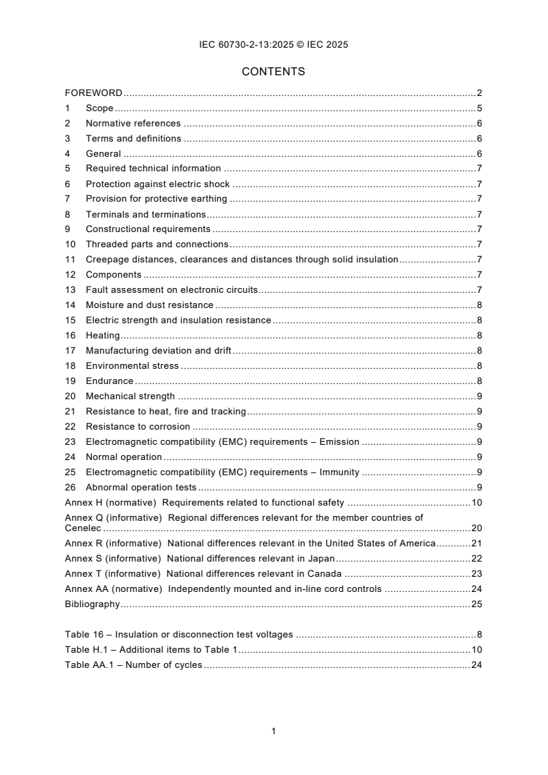
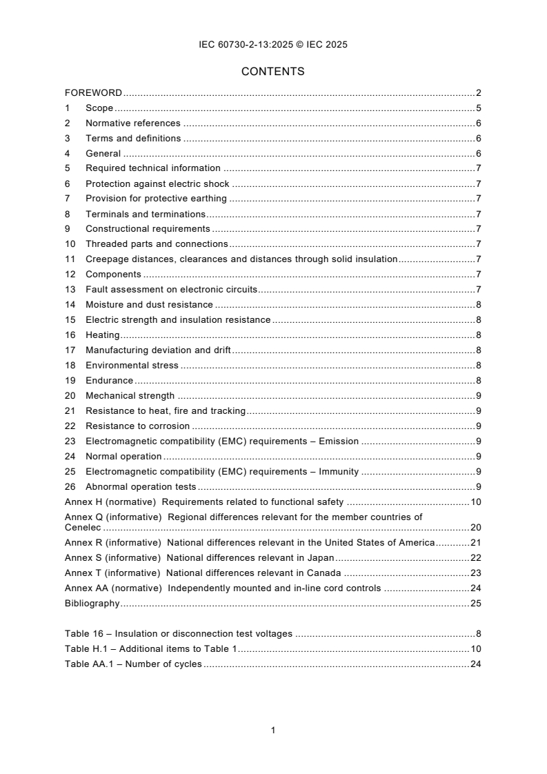
CONTENTS
FOREWORD . 2
1 Scope . 5
2 Normative references . 6
3 Terms and definitions . 6
4 General . 6
5 Required technical information . 7
6 Protection against electric shock . 7
7 Provision for protective earthing . 7
8 Terminals and terminations . 7
9 Constructional requirements . 7
10 Threaded parts and connections . 7
11 Creepage distances, clearances and distances through solid insulation . 7
12 Components . 7
13 Fault assessment on electronic circuits. 7
14 Moisture and dust resistance . 8
15 Electric strength and insulation resistance . 8
16 Heating . 8
17 Manufacturing deviation and drift . 8
18 Environmental stress . 8
19 Endurance . 8
20 Mechanical strength . 9
21 Resistance to heat, fire and tracking . 9
22 Resistance to corrosion . 9
23 Electromagnetic compatibility (EMC) requirements – Emission . 9
24 Normal operation . 9
25 Electromagnetic compatibility (EMC) requirements – Immunity . 9
26 Abnormal operation tests . 9
Annex H (normative) Requirements related to functional safety . 10
Annex Q (informative) Regional differences relevant for the member countries of
Cenelec . 20
Annex R (informative) National differences relevant in the United States of America . 21
Annex S (informative) National differences relevant in Japan . 22
Annex T (informative) National differences relevant in Canada . 23
Annex AA (normative) Independently mounted and in-line cord controls . 24
Bibliography . 25
Table 16 – Insulation or disconnection test voltages . 8
Table H.1 – Additional items to Table 1 . 10
Table AA.1 – Number of cycles . 24
INTERNATIONAL ELECTROTECHNICAL COMMISSION
____________
Automatic electrical controls -
Part 2-13: Particular requirements for humidity sensing controls
FOREWORD
1) The International Electrotechnical Commission (IEC) is a worldwide organization for standardization comprising
all national electrotechnical committees (IEC National Committees). The object of IEC is to promote international
co-operation on all questions concerning standardization in the electrical and electronic fields. To this end and
in addition to other activities, IEC publishes International Standards, Technical Specifications, Technical Reports,
Publicly Available Specifications (PAS) and Guides (hereafter referred to as “IEC Publication(s)”). Their
preparation is entrusted to technical committees; any IEC National Committee interested in the subject dealt with
may participate in this preparatory work. International, governmental and non-governmental organizations liaising
with the IEC also participate in this preparation. IEC collaborates closely with the International Organization for
Standardization (ISO) in accordance with conditions determined by agreement between the two organizations.
2) The formal decisions or agreements of IEC on technical matters express, as nearly as possible, an international
consensus of opinion on the relevant subjects since each technical committee has representation from all
interested IEC National Committees.
3) IEC Publications have the form of recommendations for international use and are accepted by IEC National
Committees in that sense. While all reasonable efforts are made to ensure that the technical content of IEC
Publications is accurate, IEC cannot be held responsible for the way in which they are used or for any
misinterpretation by any end user.
4) In order to promote international uniformity, IEC National Committees undertake to apply IEC Publications
transparently to the maximum extent possible in their national and regional publications. Any divergence between
any IEC Publication and the corresponding national or regional publication shall be clearly indicated in the latter.
5) IEC itself does not provide any attestation of conformity. Independent certification bodies provide conformity
assessment services and, in some areas, access to IEC marks of conformity. IEC is not responsible for any
services carried out by independent certification bodies.
6) All users should ensure that they have the latest edition of this publication.
7) No liability shall attach to IEC or its directors, employees, servants or agents including individual experts and
members of its technical committees and IEC National Committees for any personal injury, property damage or
other damage of any nature whatsoever, whether direct or indirect, or for costs (including legal fees) and
expenses arising out of the publication, use of, or reliance upon, this IEC Publication or any other IEC
Publications.
8) Attention is drawn to the Normative references cited in this publication. Use of the referenced publications is
indispensable for the correct application of this publication.
9) IEC draws attention to the possibility that the implementation of this document may involve the use of (a)
patent(s). IEC takes no position concerning the evidence, validity or applicability of any claimed patent rights in
respect thereof. As of the date of publication of this document, IEC had not received notice of (a) patent(s), which
may be required to implement this document. However, implementers are cautioned that this may not represent
the latest information, which may be obtained from the patent database available at https://patents.iec.ch. IEC
shall not be held responsible for identifying any or all such patent rights.
IEC 60730-2-13 has been prepared by IEC technical committee 72: Automatic electrical
controls. It is an International Standard.
This fourth edition cancels and replaces the third edition published in 2017. This edition
constitutes a technical revision.
This edition includes the following significant technical changes with respect to the previous
edition:
a) adoption to IEC 60730-1:2022 with all of its significant changes to IEC 60730-1:2013,
IEC 60730-1:2013/AMD1:2015 and IEC 60730-1:2013/AMD2:2020.
The text of this International Standard is based on the following documents:
Draft Report on voting
72/1487/FDIS 72/1503/RVD
Full information on the voting for its approval can be found in the report on voting indicated in
the above table.
The language used for the development of this International Standard is English.
This document was drafted in accordance with ISO/IEC Directives, Part 2, and developed in
accordance with ISO/IEC Directives, Part 1 and ISO/IEC Directives, IEC Supplement, available
at www.iec.ch/members_experts/refdocs. The main document types developed by IEC are
described in greater detail at www.iec.ch/publications.
A list of all parts of the IEC 60730 series, under the general title: Automatic electrical controls,
can be found on the IEC website.
This part 2-13 is intended to be used in conjunction with IEC 60730-1. It was established on the
basis of the sixth edition of that standard (2022). Consideration may be given to future editions
of, or amendments to, IEC 60730-1.
This part 2-13 supplements or modifies the corresponding clauses in IEC 60730-1, so as to
convert that publication into the IEC standard: Particular requirements for humidity sensing
controls.
Where this part 2-13 states "addition", "modification" or "replacement", the relevant require-
ment, test specification or explanatory matter in Part 1 should be adapted accordingly.
When a particular subclause of Part 1 is not mentioned in this Part 2, that subclause applies.
In the development of a fully international standard it has been necessary to take into
consideration the differing requirements resulting from practical experience in various parts of
the world and to recognize the variation in national electrical systems and wiring rules.
The reader's attention is drawn to the fact that Annex Q, Annex R, Annex S and Annex T list all
of the "in-some-country" clauses on differing practices of a less permanent nature relating to
the subject of this document.
In this publication:
1) The following print types are used:
– requirements proper: in roman type;
– test specifications: in italic type;
– explanatory matter: in smaller roman type.
– Defined terms: bold type.
2) Subclauses, notes or items which are additional to those in Part 1 are numbered starting
from 101, additional annexes are lettered AA, BB, etc.
The committee has decided that the contents of this document will remain unchanged until the
stability date indicated on the IEC website under webstore.iec.ch in the data related to the
specific document. At this date, the document will be
• reconfirmed,
• withdrawn, or
• revised.
1 Scope
This clause of Part 1 is replaced by the following:
This document applies to automatic electrical humidity sensing controls
• for use in, on, or in association with equipment for household appliance and similar use;
NOTE 1 Throughout this document, the word "equipment" means "appliance and equipment" and "controls" means
"humidity sensing control".
• for building automation within the scope of ISO 16484 series and IEC 63044 series
(HBES/BACS);
• for equipment that is used by the public, such as equipment intended to be used in shops,
offices, hospitals, farms and commercial and industrial applications;
EXAMPLE 1 Humidity sensing controls for commercial catering, heating and air-conditioning equipment.
• that are smart enabled controls;
EXAMPLE 2 Smart grid control, remote interfaces/control of energy-consuming equipment including computer or
smart phone.
• that are AC or DC powered controls with a rated voltage not exceeding 690 V AC or 600 V
DC;
• used in, on, or in association with equipment that use electricity, gas, oil, solid fuel, solar
thermal energy, etc., or a combination thereof;
• utilized as part of a control system or controls which are mechanically integral with
multifunctional controls having non-electrical outputs;
• using NTC or PTC thermistors and to discrete thermistors, requirements for which are
contained in Annex J;
• that are mechanically or electrically operated, responsive to or controlling such
characteristics as temperature, pressure, passage of time, humidity, light, electrostatic
effects, flow, or liquid level, current, voltage, acceleration, or combinations thereof;
• as well as manual controls when such are electrically and/or mechanically integral with
automatic controls.
NOTE 2 Requirements for manually actuated mechanical switches not forming part of an automatic control are
contained in IEC 61058-1-1.
This document applies to
– the inherent safety of automatic electrical humidity sensing controls, and
– functional safety of automatic electrical humidity sensing controls and safety related
systems,
– humidity sensing controls where the performance (for example the effect of EMC
phenomena) of the product can impair the overall safety and performance of the controlled
system,
– the operating values, operating times, and operating sequences where such are associated
with equipment safety.
This document specifies the requirements for construction, operation and testing of automatic
electrical humidity sensing controls used in, on, or in association with an equipment.
This document does not
• apply to automatic electrical humidity sensing controls intended exclusively for industrial
process applications unless explicitly mentioned in the relevant part 2 or the equipment
standard. However, this document can be applied to evaluate humidity sensing controls
intended specifically for industrial applications in cases where no relevant safety standard
exists;
• take into account the response value of an automatic action of a humidity sensing control,
if such a response value is dependent upon the method of mounting the humidity sensing
control in the equipment. Where a response value is of significant purpose for the protection
of the user, or surroundings, the value defined in the appropriate equipment standard or as
determined by the manufacturer will apply;
• address the integrity of the output signal to the network devices, such as interoperability
with other devices unless it has been evaluated as part of the control system.
2 Normative references
This clause of Part 1 is applicable.
3 Terms and definitions
This clause of Part 1 is applicable except as follows:
3.2 Definitions of types of control according to purpose
Additional definitions:
3.2.101
humidity sensing control
automatic electrical control which is either intended to keep the controlled humidity above,
below or between a particular value(s)
3.2.102
room humidistat
independently mounted or incorporated humidity sensing control intended to control the
humidity of habitable space
3.3 Definitions relating to the function of controls
3.3.101
permanent operation
continuous monitoring of the protective function during the operation of the appliance or system
for longer than 24 h
Note 1 to entry: 24 h is considered the typical time interval between a first and a second fault.
3.3.102
non-permanent operation
continuous monitoring of the protective function during the operation of the appliance or system
for less than 24 h
Note 1 to entry: 24 h is considered the typical time interval between a first and a second fault.
4 General
This clause of Part 1 is applicable.
5 Required technical information
This clause of Part 1 is applicable.
6 Protection against electric shock
This clause of Part 1 is applicable.
7 Provision for protective earthing
This clause of Part 1 is applicable.
8 Terminals and terminations
This clause of Part 1 is applicable.
9 Constructional requirements
This clause of Part 1 is applicable.
10 Threaded parts and connections
This clause of Part 1 is applicable.
11 Creepage distances, clearances and distances through solid insulation
This clause of Part 1 is applicable.
12 Components
This clause of Part 1 is applicable.
13 Fault assessment on electronic circuits
This clause of Part 1 is applicable except as follows:
13.1 Fault assessment for inherent safety
13.1.3 Component fault assessment
13.1.3.2 Test procedure
Modification:
Replace the first line with the following:
The control shall be operated under the following conditions. In addition, controls declared
under Table H.1, requirement 101 shall be tested when the control is in the declared condition
and when it is not.
13.1.3.8 Compliance criteria
Modification:
Item c) is not applicable.
14 Moisture and dust resistance
This clause of Part 1 is applicable.
15 Electric strength and insulation resistance
This clause of Part 1 is applicable except as follows:
Table 16 – Insulation or disconnection test voltages
Addition to footnote m:
In the case of humidity sensing controls, it can be necessary to provide specially calibrated samples to enable this
test to be performed.
16 Heating
This clause of Part 1 is applicable.
17 Manufacturing deviation and drift
This clause of Part 1 is applicable.
18 Environmental stress
This clause of Part 1 is applicable.
19 Endurance
This clause of Part 1 is applicable except as follows:
19.1 General requirements
19.1.6 Test sequence and conditions
Additional subclause:
19.1.6.101 For humidity sensing controls, the tests of Clause 19 are conducted with the
activating quantity agreed between the manufacturer and testing authority.
19.8 Test of automatic action at accelerated rate
19.8.4 Additional subclause:
19.8.4.101 The number of automatic and manual cycles for independently mounted and
in-line cord controls shall be as indicated in Annex AA, unless a higher number is declared
by the manufacturer.
19.15 Test for particular purpose controls
Additional subclause:
19.15.101 Tests for humidity sensing controls
• Subclauses 19.1 to 19.5 inclusive are applicable.
• Subclause 19.6 is applicable to actions classified as type 1.M or 2.M, the value of "X" being
agreed between manufacturer and testing authority.
• Subclause 19.7 is applicable.
• Subclause 19.8 is applicable.
• Subclause 19.9 is applicable, except for the last paragraph of 19.9.3.
• Subclauses 19.10 to 19.14 inclusive are applicable.
20 Mechanical strength
This clause of Part 1 is applicable.
21 Resistance to heat, fire and tracking
This clause of Part 1 is applicable.
22 Resistance to corrosion
This clause of Part 1 is applicable.
23 Electromagnetic compatibility (EMC) requirements – Emission
This clause of Part 1 is applicable.
24 Normal operation
This clause of Part 1 is applicable.
25 Electromagnetic compatibility (EMC) requirements – Immunity
This clause of Part 1 is applicable.
26 Abnormal operation tests
This clause of Part 1 is applicable.
Annex H
(normative)
Requirements related to functional safety
This annex of Part 1 is applicable except as follows:
H.5 Information
Table H.1 – Additional items to Table 1
Additional items:
Information Clause or Method
subclause
H.101 H.25.5.2.2 X
The output condition of Type 2 humidity sensing controls after operation
H.102 Frequency of the defined state test function H.13.2.2.2, X
H.13.2.3.2,
H.13.2.3.3
H.103 The control is for permanent operation or non-permanent operation 3.3.101, X
3.3.102,
H.13.2.2.2,
H.13.2.3.2
Additional footnote:
In general, humidity sensing controls perform class A control functions.
H.9 Constructional requirements
H.9.12 Controls using software
H.9.12.2 Measures to control faults/errors
H.9.12.2.6 Modification:
Replace the second paragraph with the following note:
NOTE 101 The values declared in Table H.1, requirement H.8, can be given in the applicable appliance standard.
H.9.12.2.7 Additional note:
NOTE 101 The values declared in Table H.1, requirement H.9, can be given in the applicable appliance standard.
H.13 Fault assessment on electronic circuits
H.13.2 Fault assessment to ensure functional safety
H.13.2.2 Class B control function
H.13.2.2.2 First fault
Modification:
Replace item b) as follows:
b) the control shall react within the fault reaction time (see Table H.1, requirement H.11) by
proceeding to the defined state provided that a subsequent restart under the same fault
conditions results in the system returning to the same defined state condition;
Replace item c) as follows:
c) for systems with non-permanent operation only, the control shall continue to operate as
intended, the fault shall be detected during the next start-up sequence. The compliance
criteria shall be a) or b).
NOTE Requirements for systems with permanent operation are under consideration.
Replace item d) as follows:
d) the control shall continue to operate as intended.
Replace the last two paragraphs with the following:
The fault reaction time shall be declared by the manufacturer (see Table H.1,
requirement H.11).
For permanent operation as declared by the manufacturer (see Table H.1, requirement
H.103), item c) is under consideration.
For a control function, where a mechanical actuator is part of a circuit that characterizes the
defined state, a test up to, but not including, the switching contacts is sufficient. If the test of
the defined state fails
...
IEC 60730-2-13 ®
Edition 4.0 2025-08
INTERNATIONAL
STANDARD
EXTENDED VERSION
This full version of IEC 60730-2-13:2025 includes the content of the references made
to IEC 60730-1:2022
Automatic electrical controls -
Part 2-13: Particular requirements for humidity sensing controls
ICS 97.120 ISBN 978-2-8327-0671-8
All rights reserved. Unless otherwise specified, no part of this publication may be reproduced or utilized in any form or
by any means, electronic or mechanical, including photocopying and microfilm, without permission in writing from either
IEC or IEC's member National Committee in the country of the requester. If you have any questions about IEC copyright
or have an enquiry about obtaining additional rights to this publication, please contact the address below or your local
IEC member National Committee for further information.
IEC Secretariat Tel.: +41 22 919 02 11
3, rue de Varembé info@iec.ch
CH-1211 Geneva 20 www.iec.ch
Switzerland
About the IEC
The International Electrotechnical Commission (IEC) is the leading global organization that prepares and publishes
International Standards for all electrical, electronic and related technologies.
About IEC publications
The technical content of IEC publications is kept under constant review by the IEC. Please make sure that you have the
latest edition, a corrigendum or an amendment might have been published.
IEC publications search - IEC Products & Services Portal - products.iec.ch
webstore.iec.ch/advsearchform Discover our powerful search engine and read freely all the
The advanced search enables to find IEC publications by a publications previews, graphical symbols and the glossary.
variety of criteria (reference number, text, technical With a subscription you will always have access to up to date
committee, …). It also gives information on projects, content tailored to your needs.
replaced and withdrawn publications.
Electropedia - www.electropedia.org
The world's leading online dictionary on electrotechnology,
IEC Just Published - webstore.iec.ch/justpublished
Stay up to date on all new IEC publications. Just Published containing more than 22 500 terminological entries in English
details all new publications released. Available online and and French, with equivalent terms in 25 additional languages.
once a month by email. Also known as the International Electrotechnical Vocabulary
(IEV) online.
IEC Customer Service Centre - webstore.iec.ch/csc
If you wish to give us your feedback on this publication or
need further assistance, please contact the Customer
Service Centre: sales@iec.ch.
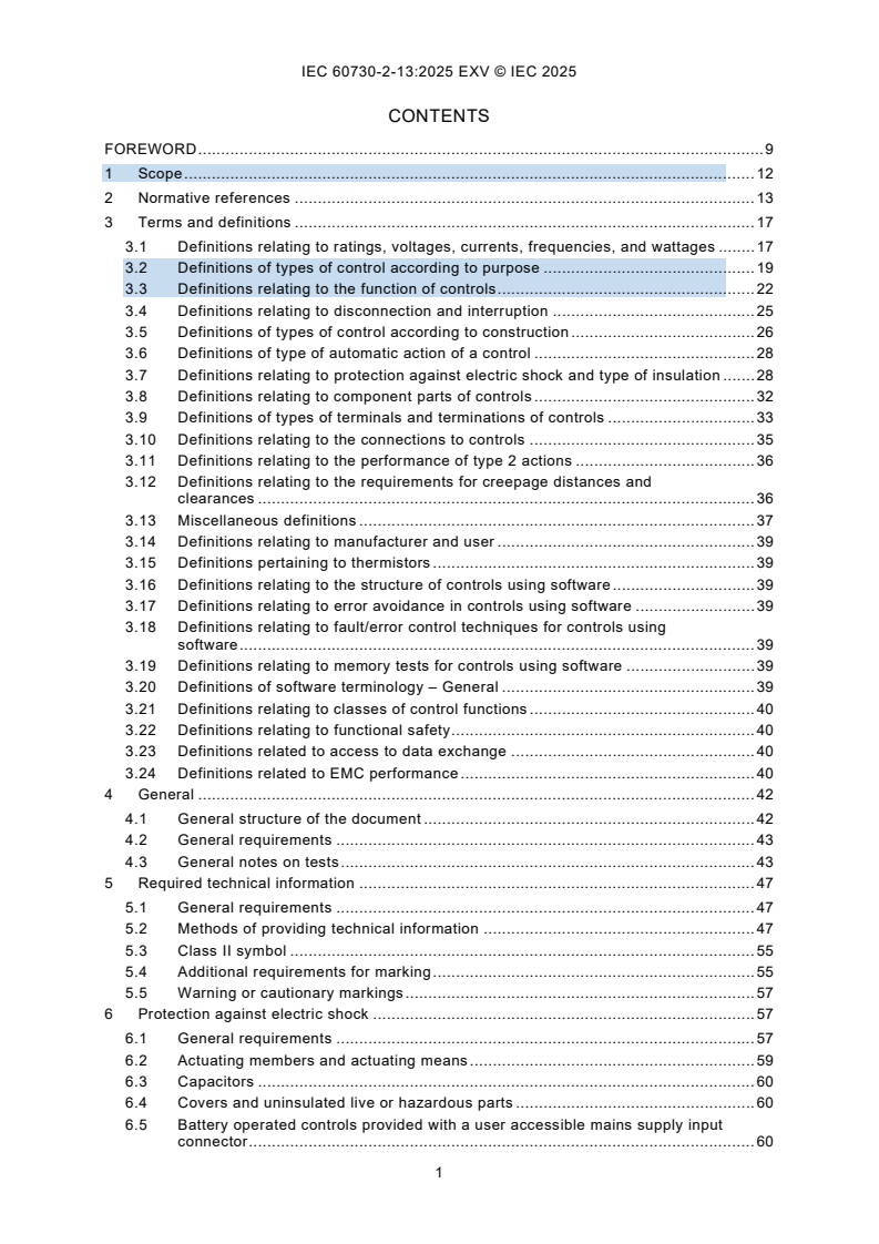
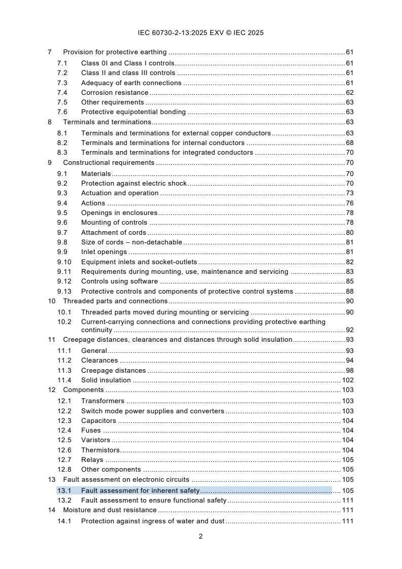
CONTENTS
FOREWORD . 9
1 Scope . 12
2 Normative references . 13
3 Terms and definitions . 17
3.1 Definitions relating to ratings, voltages, currents, frequencies, and wattages . 17
3.2 Definitions of types of control according to purpose . 19
3.3 Definitions relating to the function of controls . 22
3.4 Definitions relating to disconnection and interruption . 25
3.5 Definitions of types of control according to construction . 26
3.6 Definitions of type of automatic action of a control . 28
3.7 Definitions relating to protection against electric shock and type of insulation . 28
3.8 Definitions relating to component parts of controls . 32
3.9 Definitions of types of terminals and terminations of controls . 33
3.10 Definitions relating to the connections to controls . 35
3.11 Definitions relating to the performance of type 2 actions . 36
3.12 Definitions relating to the requirements for creepage distances and
clearances . 36
3.13 Miscellaneous definitions . 37
3.14 Definitions relating to manufacturer and user . 39
3.15 Definitions pertaining to thermistors . 39
3.16 Definitions relating to the structure of controls using software . 39
3.17 Definitions relating to error avoidance in controls using software . 39
3.18 Definitions relating to fault/error control techniques for controls using
software . 39
3.19 Definitions relating to memory tests for controls using software . 39
3.20 Definitions of software terminology – General . 39
3.21 Definitions relating to classes of control functions . 40
3.22 Definitions relating to functional safety . 40
3.23 Definitions related to access to data exchange . 40
3.24 Definitions related to EMC performance . 40
4 General . 42
4.1 General structure of the document . 42
4.2 General requirements . 43
4.3 General notes on tests . 43
5 Required technical information . 47
5.1 General requirements . 47
5.2 Methods of providing technical information . 47
5.3 Class II symbol . 55
5.4 Additional requirements for marking . 55
5.5 Warning or cautionary markings . 57
6 Protection against electric shock . 57
6.1 General requirements . 57
6.2 Actuating members and actuating means . 59
6.3 Capacitors . 60
6.4 Covers and uninsulated live or hazardous parts . 60
6.5 Battery operated controls provided with a user accessible mains supply input
connector . 60
7 Provision for protective earthing . 61
7.1 Class 0I and Class I controls. 61
7.2 Class II and class III controls . 61
7.3 Adequacy of earth connections . 61
7.4 Corrosion resistance . 62
7.5 Other requirements . 63
7.6 Protective equipotential bonding . 63
8 Terminals and terminations. 63
8.1 Terminals and terminations for external copper conductors . 63
8.2 Terminals and terminations for internal conductors . 68
8.3 Terminals and terminations for integrated conductors . 70
9 Constructional requirements . 70
9.1 Materials . 70
9.2 Protection against electric shock . 70
9.3 Actuation and operation . 73
9.4 Actions . 76
9.5 Openings in enclosures . 78
9.6 Mounting of controls . 78
9.7 Attachment of cords . 80
9.8 Size of cords – non-detachable . 81
9.9 Inlet openings . 81
9.10 Equipment inlets and socket-outlets . 82
9.11 Requirements during mounting, use, maintenance and servicing . 83
9.12 Controls using software . 85
9.13 Protective controls and components of protective control systems . 88
10 Threaded parts and connections . 90
10.1 Threaded parts moved during mounting or servicing . 90
10.2 Current-carrying connections and connections providing protective earthing
continuity . 92
11 Creepage distances, clearances and distances through solid insulation . 93
11.1 General . 93
11.2 Clearances . 94
11.3 Creepage distances . 98
11.4 Solid insulation . 102
12 Components . 103
12.1 Transformers . 103
12.2 Switch mode power supplies and converters . 103
12.3 Capacitors . 104
12.4 Fuses . 104
12.5 Varistors . 104
12.6 Thermistors. 104
12.7 Relays . 105
12.8 Other components . 105
13 Fault assessment on electronic circuits . 105
13.1 Fault assessment for inherent safety . 105
13.2 Fault assessment to ensure functional safety . 111
14 Moisture and dust resistance . 111
14.1 Protection against ingress of water and dust . 111
14.2 Protection against humid conditions . 112
14.3 Touch current test for in-line cord controls and free-standing controls . 113
15 Electric strength and insulation resistance . 114
15.1 Insulation resistance . 114
15.2 Electric strength . 114
15.3 Additional tests for in-line cord and free-standing controls . 116
16 Heating . 117
17 Manufacturing deviation and drift . 122
18 Environmental stress . 122
18.1 Transportation and storage . 122
18.2 Environmental stress of temperature . 122
19 Endurance . 123
19.1 General requirements . 123
19.2 Electrical conditions for the tests . 124
19.3 Thermal conditions for the tests . 130
19.4 Manual and mechanical conditions for the tests . 130
19.5 Dielectric strength requirements. 131
19.6 Ageing test . 131
19.7 Overvoltage test or overload test in all countries using an overload test of
automatic action at accelerated rate . 131
19.8 Test of automatic action at accelerated rate . 132
19.9 Test of automatic action at slow rate . 132
19.10 Overvoltage test or overload test in all countries that use the overload test of
manual action at accelerated speed . 133
19.11 Test of manual action at slow speed . 133
19.12 Test of manual action at high speed which has multiple poles, and where
polarity reversal occurs during the action . 133
19.13 Test of manual action at accelerated speed . 133
19.14 Evaluation of compliance . 134
19.15 Test for particular purpose controls . 134
20 Mechanical strength . 135
20.1 General requirements . 135
20.2 Impact resistance . 135
20.3 Free-standing controls . 136
20.4 In-line cord controls . 136
20.5 Pull-cord actuated controls . 137
20.6 Foot actuated controls . 137
20.7 Actuating member and actuating means . 137
20.8 Flexing – test . 138
20.9 Cord anchorages – test . 138
21 Resistance to heat, fire and tracking . 139
21.1 General requirements . 139
21.2 Integrated, incorporated and in-line cord controls. 139
21.3 Independently mounted, free-standing controls . 141
22 Resistance to corrosion . 141
22.1 Resistance to rusting . 141
23 Electromagnetic compatibility (EMC) requirements – Emission . 141
23.1 General requirement . 141
23.2 High frequency emission . 142
23.3 Low frequency emission . 145
24 Normal operation . 145
25 Electromagnetic compatibility (EMC) requirements – Immunity . 145
25.1 General . 145
25.2 EMC test plan and report . 146
25.3 Immunity requirements . 148
25.4 Performance criteria . 151
25.5 Surge immunity test . 152
25.6 Electrical fast transient immunity test . 152
25.7 Radio-frequency electromagnetic field immunity . 153
25.8 Electrostatic discharge . 153
25.9 Immunity to power-frequency magnetic fields . 153
25.10 Test of the influence of voltage dips and voltage interruption in the power
supply network . 153
26 Abnormal operation tests . 154
26.1 Abnormal temperature test . 154
26.2 Overload tests . 155
26.3 Battery short-circuit test . 156
Annex A (normative) Indelibility of markings . 173
Annex B (normative) Measurement of creepage distances and clearances in air . 175
Annex C (informative) Nominal voltages of supply systems for different modes of
overvoltage control . 179
Annex D (normative) Overvoltage categories . 181
Annex E (informative) Typical usage of controls and related overvoltage categories . 182
Annex F (normative) Pollution degrees . 183
F.1 Pollution . 183
F.2 Degrees of pollution in the micro-environment . 183
Annex G (normative) Resistance to heat, fire and tracking tests . 184
G.1 Glow-wire test . 184
G.2 Proof tracking test . 184
G.3 Ball pressure test . 184
Annex H (normative) Requirements related to functional safety . 186
H.3 Terms and definitions. 186
H.5 Information . 197
H.9 Constructional requirements . 199
H.13 Fault assessment on electronic circuits . 215
H.17 Manufacturing deviation and drift . 219
H.19 Endurance . 221
H.25 Electromagnetic compatibility (EMC) requirements – Immunity. 222
Annex I (normative) Requirements for certain types of DC supplied controls . 239
I.1 Scope . 239
Annex J (normative) Requirements for thermistor elements and controls using
thermistors . 241
J.1 Scope . 241
Annex K (normative) Circuit for measuring touch current . 258
Annex L (normative) Printed circuit board coating performance test . 259
Annex M (normative) Printed circuit board protection . 261
Annex N (informative) Explanatory notes for surge immunity test . 264
N.1 Different source impedances . 264
N.2 Application of the tests. 264
N.3 Installation classification . 265
Annex O (informative) Guidance for applying Clause 11 . 268
Annex P (normative) Requirements for SELV and PELV . 271
P.1 Overview of the requirements for SELV and PELV . 271
P.2 Protection against electric shock by SELV system or PELV system . 271
P.3 Protective measures for SELV system and PELV system . 272
Annex Q (informative) Regional differences relevant for the member countries of
Cenelec . 274
Q.2 Normative references . 274
Annex R (informative) National differences relevant in the United States of America . 278
R.2 Normative references . 278
Annex S (informative) National differences relevant in Japan . 279
S.2 Normative references . 279
Annex T (informative) National differences relevant in Canada . 280
T.2 Normative references . 280
Annex AA (normative) Independently mounted and in-line cord controls . 281
Bibliography . 282
Figure 1 – Example of ports . 40
Figure 2 – Structure of the document with respect to inherent safety and functional
safety . 43
Figure 3 – Example of an electronic circuit with low power points . 106
Figure 4 – Test pin probe 13 of IEC 61032:1997 . 156
Figure 5 – Test finger probe B of IEC 61032:1997 . 157
Figure 6 – Test fingernail . 158
Figure 7 – Impact test for free-standing controls . 159
Figure 8 – Tumbling barrel . 159
Figure 9 – Apparatus for testing durability of markings on rating labels . 160
Figure 10 – Apparatus for flexing test . 160
Figure 11 – Screw terminals and stud terminals . 161
Figure 12 – Pillar terminals . 162
Figure 13 – Mantle terminals . 163
Figure 14 – Saddle and lug terminals . 164
Figure 15 – Tabs. 165
Figure 16 – Tabs for non-reversible connectors . 166
Figure 17 – Receptacles . 167
Figure 18 – Measurement of creepage distance and clearance . 168
Figure 19 – Diagram for touch current measurement at operating temperature for
single-phase connection of class II controls . 169
Figure 20 – Diagram for touch current measurement at operating temperature for
single-phase connection of controls other than class II . 169
Figure 21 – Diagram for touch current measurement at operating temperature for
three-phase connection of class II controls . 170
Figure 22 – Diagram for touch current measurement at operating temperature for
three-phase connection of controls other than class II . 171
Figure 23 – Diagram for touch current measurement at operating temperature for
single-phase connection of controls to three-wire, ground neutral supply other than
class II . 171
Figure 24 – Diagram for touch current measurement at operating temperature for
two‑phase connection of controls to three-wire, ground neutral supply other
than class II . 172
Figure B.1 – Narrow groove . 176
Figure B.2 – Wide groove . 176
Figure B.3 – V-shaped groove . 176
Figure B.4 – Rib . 176
Figure B.5 – Uncemented joint with narrow groove . 177
Figure B.6 – Uncemented joint with wide groove . 177
Figure B.7 – Uncemented joint with narrow and wide grooves . 177
Figure B.8 – Diverging side walls . 178
Figure B.9 – Narrow recess . 178
Figure B.10 – Wide recess . 178
Figure B.11 – Conductive floating part . 178
Figure H.1 – V-Model for the software life cycle . 207
Figure H.2 – Voltage variation test . 226
Figure J.1 – Generic test circuit for inrush-current limiting thermistor endurance test . 257
Figure K.1 – Circuit for measuring touch currents . 258
Figure L.1 – Test sample . 260
Figure M.1 – Example of type 1 protection . 262
Figure M.2 – Example of type 2 protection . 263
Figure N.1 – Example of surge protection by shielding in buildings with common earth
reference systems . 266
Figure N.2 – Example of secondary surge protection in buildings with separate
common earth reference systems . 267
Figure N.3 – Example of primary and secondary surge protection of indoor/outdoor
equipment . 267
Figure O.1 – Guidance flowchart for application of requirements of Clause 11 . 269
Table 1 – Required technical information and methods of providing these information . 50
Table 2 – Cross-sectional area of conductors . 64
Table 3 – Terminal conductors . 66
Table 4 – Conductor pull test values . 66
Table 5 – Nominal cross-sectional areas of conductors . 68
Table 6 – Axial force values for tab insertion and withdrawal . 69
Table 7 – Minimum cord conductor sizes . 81
Table 8 – Data exchange . 86
Table 9 – Threaded parts torque test values . 92
Table 10 – Rated impulse voltage for equipment energized directly from the supply
mains (from IEC 60664-1:2007, Table F.1) . 95
Table 11 – Clearances for insulation co-ordination (from IEC 60664-1:2007, Table F.2). 96
Table 12 – Minimum creepage distances for basic insulation . 100
Table 13 – Minimum creepage distances for functional insulation . 101
Table 14 – Electrical/electronic component fault modes . 107
Table 15 – Minimum insulation resistance . 114
Table 16 – Insulation or disconnection test voltages . 115
Table 17 – Maximum heating temperatures . 120
Table 18 – Electrical conditions for the overvoltage and endurance tests . 126
Table 19 – Electrical conditions for the overload tests of 19.7 and 19.10 . 128
Table 20 – Electrical conditions for the endurance tests of 19.8, 19.9, 19.11, 19.12 and
19.13 . 129
Table 21 – Pull-cord force test values . 137
Table 22 – Pull and torque values . 138
Table 23 – Emission limit for residential electromagnetic environment . 143
Table 24 – Emission limit for industrial electromagnetic environment . 144
Table 25 – The applicable EMC test in relation to the class of control function and type
of Action . 146
Table 26 – Immunity test requirements for residential electromagnetic environments . 148
Table 27 – Immunity test requirements for industrial electromagnetic environment . 150
Table 28 – Performance criteria . 152
Table 29 – Maximum winding temperature (for test of mechanical blocked output
conditions) . 155
Table B.1 – Value of X . 175
Table C.1 – Inherent control or equivalent protective control . 179
Table C.2 – Cases where protective control is necessary and control is provided by
surge arresters having a ratio of clamping voltage to rated voltage not smaller than
that specified by IEC 60099-1 . 180
Table E.1 – Typical usage. 182
Table H.1 – Additional items to Table 1 . 197
a
Table H.2 – Acceptable measures to address fault/errors . 200
Table H.3 – Examples of techniques/measures for semi-formal methods . 207
Table H.4 – Examples of techniques/measures for software architecture specification . 208
Table H.5 – Examples of techniques/measures for module design specification . 209
Table H.6 – Examples of techniques/measures for design and coding standards . 209
Table H.7 – Examples of techniques/measures for software module testing . 210
Table H.8 – Examples of techniques/measures for software integration testing . 211
Table H.9 – Examples of techniques/measures for software safety validation . 211
Table H.10 – Combinations of analytical measures during hardware development . 212
Table H.11 – Examples of defences against unauthorised access and transmission
failure modes . 214
Table H.12 – Applicable test levels in addition to Clause 25. 222
Table H.13 – Voltage dips, short interruptions and voltage variations . 224
Table H.14 – Test values for voltage variations . 225
Table H.15 – Test voltages for test level 2 (depending on the installation class
conditions) . 228
Table H.16 – Test level for electrical fast transient burst test . 230
Table H.17 – Test levels for conducted disturbances on mains and I/O lines . 232
Table H.18 – Test level for immunity to radiated electromagnetic fields . 233
Table H.19 – Increased test level for radiated immunity . 234
Table H.20 – Test level for supply frequency variations . 235
Table H.21 – Test level for continuous fields . 236
Table I.1 – Electrical transient conduction immunity in accordance with ISO 7637-2 . 239
Table I.2 – Electrical transient conduction immunity in accordance with ISO 7637-3 . 240
Table J.1 – Maximum current . 243
Table J.2 – Normal operating conditions . 244
Table J.3 – Samples for the test (clause reference) . 245
Table J.4 – Electrical and thermal ratings of a thermistor . 246
Table J.5 – Additional items to Table 1 . 247
Table J.6 – Sequence of calibration and conditioning tests for PTC thermistors . 249
Table J.7 – Classes for PTC sensing thermistors . 250
Table J.8 – Sequence of calibration and conditioning tests for NTC thermistors . 251
Table J.9 – Classes for NTC sensing thermistors . 251
Table J.10 – Number of cycles for endurance test . 255
Table J.11 – Ageing test temperature . 255
Table J.12 – Number of cycles for endurance test . 256
Table L.1 – Environmental cycling conditions . 259
Table M.1 – IEC 60664-3 test levels or conditions . 261
Table O.1 – Example A – Using Annex O guidance for applying Clause 11 . 270
Table O.2 – Example B – Using Annex O guidance for applying Clause 11 . 270
Table Q.1 – Additional aging parameters for windings . 275
Table AA.1 – Number of cycles . 281
INTERNATIONAL ELECTROTECHNICAL COMMISSION
____________
Automatic electrical controls -
Part 2-13: Particular requirements for humidity sensing controls
FOREWORD
1) The International Electrotechnical Commission (IEC) is a worldwide organization for standardization comprising
all national electrotechnical committees (IEC National Committees). The object of IEC is to promote international
co-operation on all questions concerning standardization in the electrical and electronic fields. To this end and
in addition to other activities, IEC publishes International Standards, Technical Specifications, Technical Reports,
Publicly Available Specifications (PAS) and Guides (hereafter referred to as “IEC Publication(s)”
...
IEC 60730-2-13 ®
Edition 4.0 2025-08
NORME
INTERNATIONALE
Dispositifs de commande électrique automatiques -
Partie 2-13: Exigences particulières pour les dispositifs de commande sensibles
à l'humidité
ICS 97.120 ISBN 978-2-8327-0596-4
Droits de reproduction réservés. Sauf indication contraire, aucune partie de cette publication ne peut être reproduite ni
utilisée sous quelque forme que ce soit et par aucun procédé, électronique ou mécanique, y compris la photocopie et
les microfilms, sans l'accord écrit de l'IEC ou du Comité national de l'IEC du pays du demandeur. Si vous avez des
questions sur le copyright de l'IEC ou si vous désirez obtenir des droits supplémentaires sur cette publication, utilisez
les coordonnées ci-après ou contactez le Comité national de l'IEC de votre pays de résidence.
IEC Secretariat Tel.: +41 22 919 02 11
3, rue de Varembé info@iec.ch
CH-1211 Geneva 20 www.iec.ch
Switzerland
A propos de l'IEC
La Commission Electrotechnique Internationale (IEC) est la première organisation mondiale qui élabore et publie des
Normes internationales pour tout ce qui a trait à l'électricité, à l'électronique et aux technologies apparentées.
A propos des publications IEC
Le contenu technique des publications IEC est constamment revu. Veuillez vous assurer que vous possédez l’édition la
plus récente, un corrigendum ou amendement peut avoir été publié.
Recherche de publications IEC - IEC Products & Services Portal - products.iec.ch
webstore.iec.ch/advsearchform Découvrez notre puissant moteur de recherche et consultez
La recherche avancée permet de trouver des publications gratuitement tous les aperçus des publications, symboles
IEC en utilisant différents critères (numéro de référence, graphiques et le glossaire. Avec un abonnement, vous aurez
texte, comité d’études, …). Elle donne aussi des toujours accès à un contenu à jour adapté à vos besoins.
informations sur les projets et les publications remplacées
ou retirées. Electropedia - www.electropedia.org
Le premier dictionnaire d'électrotechnologie en ligne au
IEC Just Published - webstore.iec.ch/justpublished monde, avec plus de 22 500 articles terminologiques en
Restez informé sur les nouvelles publications IEC. Just anglais et en français, ainsi que les termes équivalents
dans 25 langues additionnelles. Egalement appelé
Published détaille les nouvelles publications parues.
Disponible en ligne et une fois par mois par email. Vocabulaire Electrotechnique International (IEV) en ligne.
Service Clients - webstore.iec.ch/csc
Si vous désirez nous donner des commentaires sur cette
publication ou si vous avez des questions contactez-
nous: sales@iec.ch.
SOMMAIRE
AVANT-PROPOS . 2
1 Domaine d'application . 5
2 Références normatives . 6
3 Termes et définitions . 6
4 Généralités . 7
5 Informations techniques exigées . 7
6 Protection contre les chocs électriques . 7
7 Dispositions en vue de la mise à la terre de protection . 7
8 Bornes et connexions . 7
9 Exigences de construction . 7
10 Parties filetées et connexions . 7
11 Lignes de fuite, distances dans l'air et distances à travers l'isolation solide . 7
12 Éléments constituants. 7
13 Évaluation des pannes sur les circuits électroniques . 8
14 Résistance à l'humidité et à la poussière . 8
15 Résistance d'isolement et rigidité diélectrique . 8
16 Échauffements. 8
17 Tolérances de fabrication et dérive . 8
18 Contraintes climatiques . 8
19 Endurance . 9
20 Résistance mécanique . 9
21 Résistance à la chaleur, au feu et aux courants de cheminement . 9
22 Résistance à la corrosion . 9
23 Exigences de compatibilité électromagnétique (CEM) – Émission . 9
24 Fonctionnement normal . 10
25 Exigences de compatibilité électromagnétique (CEM) – Immunité . 10
26 Essais en fonctionnement anormal . 10
Annexe H (normative) Exigences relatives à la sécurité fonctionnelle . 11
Annexe Q (informative) Différences régionales pertinentes pour les pays membres du
CENELEC . 23
Annexe R (informative) Différences nationales applicables aux États-Unis. 24
Annexe S (informative) Différences nationales applicables au Japon . 25
Annexe T (informative) Différences nationales applicables au Canada . 26
Annexe AA (normative) Dispositifs de commande à montage indépendant et intercalés
dans un câble souple . 27
Bibliographie . 28
Tableau 16 – Tensions d'essai d'isolation ou de déconnexion . 8
Tableau H.1 – Points complémentaires au Tableau 1 . 11
Tableau AA.1 – Nombre de cycles . 27
COMMISSION ÉLECTROTECHNIQUE INTERNATIONALE
____________
Dispositifs de commande électrique automatiques -
Partie 2-13: Exigences particulières pour les dispositifs
de commande sensibles à l'humidité
AVANT-PROPOS
1) La Commission Électrotechnique Internationale (IEC) est une organisation mondiale de normalisation composée
de l'ensemble des comités électrotechniques nationaux (Comités nationaux de l'IEC). L'IEC a pour objet de
favoriser la coopération internationale pour toutes les questions de normalisation dans les domaines de
l'électricité et de l'électronique. À cet effet, l'IEC – entre autres activités – publie des Normes internationales,
des Spécifications techniques, des Rapports techniques, des Spécifications accessibles au public (PAS) et des
Guides (ci-après dénommés "Publication(s) de l'IEC"). Leur élaboration est confiée à des comités d'études, aux
travaux desquels tout Comité national intéressé par le sujet traité peut participer. Les organisations
internationales, gouvernementales et non gouvernementales, en liaison avec l'IEC, participent également aux
travaux. L'IEC collabore étroitement avec l'Organisation Internationale de Normalisation (ISO), selon des
conditions fixées par accord entre les deux organisations.
2) Les décisions ou accords officiels de l'IEC concernant les questions techniques représentent, dans la mesure du
possible, un accord international sur les sujets étudiés, étant donné que les Comités nationaux de l'IEC intéressés
sont représentés dans chaque comité d'études.
3) Les Publications de l'IEC se présentent sous la forme de recommandations internationales et sont agréées
comme telles par les Comités nationaux de l'IEC. Tous les efforts raisonnables sont entrepris afin que l'IEC
s'assure de l'exactitude du contenu technique de ses publications; l'IEC ne peut pas être tenue responsable de
l'éventuelle mauvaise utilisation ou interprétation qui en est faite par un quelconque utilisateur final.
4) Dans le but d'encourager l'uniformité internationale, les Comités nationaux de l'IEC s'engagent, dans toute la
mesure possible, à appliquer de façon transparente les Publications de l'IEC dans leurs publications nationales
et régionales. Toutes divergences entre toutes Publications de l'IEC et toutes publications nationales ou
régionales correspondantes doivent être indiquées en termes clairs dans ces dernières.
5) L'IEC elle-même ne fournit aucune attestation de conformité. Des organismes de certification indépendants
fournissent des services d'évaluation de conformité et, dans certains secteurs, accèdent aux marques de
conformité de l'IEC. L'IEC n'est responsable d'aucun des services effectués par les organismes de certification
indépendants.
6) Tous les utilisateurs doivent s'assurer qu'ils sont en possession de la dernière édition de cette publication.
7) Aucune responsabilité ne doit être imputée à l'IEC, à ses administrateurs, employés, auxiliaires ou mandataires,
y compris ses experts particuliers et les membres de ses comités d'études et des Comités nationaux de l'IEC,
pour tout préjudice causé en cas de dommages corporels et matériels, ou de tout autre dommage de quelque
nature que ce soit, directe ou indirecte, ou pour supporter les coûts (y compris les frais de justice) et les dépenses
découlant de la publication ou de l'utilisation de cette Publication de l'IEC ou de toute autre Publication de l'IEC,
ou au crédit qui lui est accordé.
8) L'attention est attirée sur les références normatives citées dans cette publication. L'utilisation de publications
référencées est obligatoire pour une application correcte de la présente publication.
9) L'IEC attire l'attention sur le fait que la mise en application du présent document peut entraîner l'utilisation d'un
ou de plusieurs brevets. L'IEC ne prend pas position quant à la preuve, à la validité et à l'applicabilité de tout
droit de brevet revendiqué à cet égard. À la date de publication du présent document, l'IEC n'avait pas reçu
notification qu'un ou plusieurs brevets pouvaient être nécessaires à sa mise en application. Toutefois, il y a lieu
d'avertir les responsables de la mise en application du présent document que des informations plus récentes
sont susceptibles de figurer dans la base de données de brevets, disponible à l'adresse https://patents.iec.ch.
L'IEC ne saurait être tenue pour responsable de ne pas avoir identifié de tels droits de brevets.
L'IEC 60730-2-13 a été établie par le comité d'études 72 de l'IEC: Commandes électriques
automatiques. Il s'agit d'une Norme internationale.
Cette quatrième édition annule et remplace la troisième édition parue en 2017. Cette édition
constitue une révision technique.
Cette édition inclut les modifications techniques majeures suivantes par rapport à l'édition
précédente:
a) adoption de l'IEC 60730-1:2022 avec toutes les modifications majeures par rapport
à l'IEC 60730-1:2013, l'IEC 60730-1:2013/AMD1:2015 et l'IEC 60730-1:2013/AMD2:2020.
Le texte de cette Norme internationale est issu des documents suivants:
Projet Rapport de vote
72/1487/FDIS 72/1503/RVD
Le rapport de vote indiqué dans le tableau ci-dessus donne toute information sur le vote ayant
abouti à son approbation.
La langue employée pour l'élaboration de cette Norme internationale est l'anglais.
Ce document a été rédigé selon les Directives ISO/IEC, Partie 2, il a été développé selon les
Directives ISO/IEC, Partie 1 et les Directives ISO/IEC, Supplément IEC, disponibles sous
www.iec.ch/members_experts/refdocs. Les principaux types de documents développés par
l'IEC sont décrits plus en détail sous www.iec.ch/standardsdev/publications.
Une liste de toutes les parties de la série IEC 60730, publiées sous le titre général: Dispositifs
de commande électrique automatiques, se trouve sur le site web de l'IEC.
La présente partie 2-13 est destinée à être utilisée conjointement avec l'IEC 60730-1. Elle a
été établie sur la base de la sixième édition de cette norme (2022). Les éditions futures
de l'IEC 60730-1 ou ses amendements pourront être pris en considération.
La présente partie 2-13 complète ou modifie les articles correspondants de l'IEC 60730-1, de
façon à transformer cette publication en norme IEC: Exigences particulières pour les dispositifs
de commande sensibles à l'humidité.
Lorsque la présente partie 2-13 spécifie "addition", "modification" ou "remplacement", il
convient d'adapter l'exigence, la modalité d'essai ou la note correspondante de la Partie 1 en
conséquence.
Lorsqu'un paragraphe particulier de la Partie 1 n'est pas mentionné dans cette Partie 2, ce
paragraphe s'applique.
Pour les besoins d'élaboration d'une Norme internationale, il a été nécessaire d'examiner les
différentes exigences en s'appuyant sur l'expérience pratique acquise dans différentes régions
du monde et d'identifier les variantes nationales au niveau des réseaux d'alimentation
électrique et des règles d'installation.
L'attention du lecteur est attirée sur le fait que l'Annexe Q, l'Annexe R, l'Annexe S et l'Annexe T
donnent une liste de tous les articles qui traitent des différences de pratiques à caractère moins
permanent qui existent dans certains pays dans le domaine couvert par le présent document.
Dans cette publication:
1) Les caractères d'imprimerie suivants sont utilisés:
– exigences proprement dites: caractères romains;
– modalités d'essais: caractères italiques;
– notes: petits caractères romains;
– termes définis: caractères gras.
2) Les paragraphes, notes ou articles qui s'ajoutent à ceux de la Partie 1 sont numérotés à
partir de 101 et les annexes qui sont ajoutées sont désignées AA, BB, etc.
Le comité a décidé que le contenu de ce document ne sera pas modifié avant la date de stabilité
indiquée sur le site web de l'IEC sous webstore.iec.ch dans les données relatives au document
recherché. À cette date, le document sera
• reconduit,
• supprimé, ou
• révisé.
1 Domaine d'application
L'article de la Partie 1 est remplacé par le texte suivant:
Le présent document s'applique aux dispositifs de commande électrique automatiques
sensibles à la l'humidité
• utilisés dans, sur ou avec des matériels pour appareil domestique et usage analogue;
NOTE 1 Dans le présent document, le terme "matériel" signifie "appareil et matériel" et "dispositifs de commande"
signifie "dispositifs de commande sensibles à l'humidité".
• pour l'automatisation des bâtiments qui relèvent du domaine d'application de la
série ISO 16484 et de la série IEC 63044 (HBES/BACS);
• pour des matériels utilisés par le public, tels que les matériels destinés à être utilisés dans
des magasins, des bureaux, des hôpitaux, des fermes et des applications commerciales et
industrielles;
EXEMPLE 1 Les dispositifs de commande sensibles à l'humidité pour les installations de restauration, de
chauffage et d'air conditionné.
• qui sont des dispositifs de commande activés intelligents;
EXEMPLE 2 Les dispositifs de commande de réseau intelligent, les interfaces distantes/dispositifs de commande
de matériels utilisateurs d'énergie électrique, y compris les ordinateurs ou les mobiles multifonctions.
• qui sont des dispositifs de commande à courant alternatif ou continu dont la tension
assignée ne dépasse pas 690 V en courant alternatif ou 600 V en courant continu;
• qui sont utilisés dans, sur ou avec des matériels qui utilisent l'électricité, le gaz, le pétrole,
des combustibles solides, l'énergie thermique solaire, etc. ou une combinaison de ces
sources d'énergie;
• qui sont utilisés dans le cadre d'un système de commande ou de dispositifs de commande
qui sont mécaniquement intégrés à des dispositifs de commande multifonctions comportant
des sorties non électriques;
• qui utilisent des thermistances CTN ou CTP ainsi qu'aux dispositifs à thermistances
discrètes, dont les exigences sont fournies à l'Annexe J;
• à commande mécanique ou électrique, qui réagissent à des caractéristiques telles que la
température, la pression, le passage du temps, l'humidité, la lumière, les effets
électrostatiques, le débit ou le niveau d'un liquide, le courant, la tension, l'accélération, ou
une combinaison de ces caractéristiques, ou qui les régulent;
• ainsi qu'aux dispositifs de commande manuels qui sont électriquement et/ou
mécaniquement intégrés à des dispositifs de commande automatique.
NOTE 2 Les exigences relatives aux interrupteurs mécaniques à action manuelle qui ne font pas partie d'un
dispositif de commande automatique sont contenues dans l'IEC 61058-1-1.
Le présent document s'applique
– à la sécurité intrinsèque des dispositifs de commande électrique automatiques sensibles
à l'humidité; et
– à la sécurité fonctionnelle des dispositifs de commande électrique automatiques
sensibles à l'humidité et des systèmes de sécurité;
– aux dispositifs de commande sensibles à l'humidité pour lesquels les performances (par
exemple, l'effet des phénomènes CEM) du produit peuvent compromettre la sécurité et les
performances globales du système commandé;
– aux valeurs de fonctionnement, aux temps de fonctionnement et aux séquences de
fonctionnement lorsque ces éléments interviennent dans la sécurité du matériel.
Le présent document spécifie les exigences relatives à la construction, au fonctionnement et
aux essais des dispositifs de commande électrique automatiques sensibles à l'humidité
utilisés dans, sur ou avec du matériel.
Le présent document
• ne s'applique pas aux dispositifs de commande électrique automatiques sensibles à
l'humidité destinés exclusivement à des applications de processus industriels, sauf
mention particulière dans la partie 2 applicable ou la norme du matériel. Toutefois, le
présent document peut être utilisé pour évaluer les dispositifs de commande sensibles à
l'humidité destinés spécifiquement aux applications industrielles lorsqu'il n'existe aucune
norme de sécurité pertinente;
• ne prend pas en compte la valeur de réponse d'une action automatique d'un dispositif de
commande sensible à l'humidité, lorsque cette valeur de réponse dépend de la méthode
de montage du dispositif de commande sensible à l'humidité dans le matériel.
Lorsqu'une valeur de réponse est importante du point de vue de la protection de l'utilisateur
ou de l'environnement, la valeur définie dans la norme de matériel pertinente ou déterminée
par le fabricant s'applique;
• ne traite pas de l'intégrité du signal de sortie transmis aux dispositifs de réseau, comme
l'interopérabilité avec d'autres dispositifs, à moins qu'elle ait été évaluée comme partie
intégrante du système de commande.
2 Références normatives
L'article de la Partie 1 s'applique.
3 Termes et définitions
L'article de la Partie 1 s'applique, avec les exceptions suivantes:
3.2 Définitions des différents types de dispositifs de commande en fonction de
l'application
Définitions supplémentaires:
3.2.101
dispositif de commande sensible à l'humidité
dispositif de commande électrique automatique prévu pour maintenir l'humidité contrôlée au-
dessus, au-dessous ou entre une ou des valeurs particulières
3.2.102
humidistat d'ambiance
dispositif de commande sensible à l'humidité incorporé ou pour montage indépendant,
destiné à régler l'humidité d'une zone habitable
3.3 Définitions concernant les fonctions des dispositifs de commande
3.3.101
fonctionnement permanent
surveillance continue de la fonction de protection au cours du fonctionnement de l'appareil ou
du système pendant plus de 24 h
Note 1 à l'article: La durée de 24 h est considérée comme l'intervalle de temps type entre une première panne et
une seconde panne.
3.3.102
fonctionnement non permanent
surveillance continue de la fonction de protection au cours du fonctionnement de l'appareil ou
du système pendant moins de 24 h
Note 1 à l'article: La durée de 24 h est considérée comme l'intervalle de temps type entre une première panne et
une seconde panne.
4 Généralités
L'article de la Partie 1 s'applique.
5 Informations techniques exigées
L'article de la Partie 1 s'applique.
6 Protection contre les chocs électriques
L'article de la Partie 1 s'applique.
7 Dispositions en vue de la mise à la terre de protection
L'article de la Partie 1 s'applique.
8 Bornes et connexions
L'article de la Partie 1 s'applique.
9 Exigences de construction
L'article de la Partie 1 s'applique.
10 Parties filetées et connexions
L'article de la Partie 1 s'applique.
11 Lignes de fuite, distances dans l'air et distances à travers l'isolation solide
L'article de la Partie 1 s'applique.
12 Éléments constituants
L'article de la Partie 1 s'applique.
13 Évaluation des pannes sur les circuits électroniques
L'article de la Partie 1 s'applique, avec les exceptions suivantes:
13.1 Évaluation des pannes pour la sécurité intrinsèque
13.1.3 Évaluation des pannes de composant
13.1.3.2 Procédure d'essai
Modification:
Remplacer la première ligne par le texte suivant:
Le dispositif de commande doit fonctionner dans les conditions suivantes. De plus, les
dispositifs de commande déclarés selon l'exigence 101 du Tableau H.1 doivent être soumis
à l'essai lorsque le dispositif de commande se trouve dans la condition déclarée et lorsqu'il
ne s'y trouve pas.
13.1.3.8 Critères de conformité
Modification:
Le point c) ne s'applique pas.
14 Résistance à l'humidité et à la poussière
L'article de la Partie 1 s'applique.
15 Résistance d'isolement et rigidité diélectrique
L'article de la Partie 1 s'applique, avec l'exception suivante:
Tableau 16 – Tensions d'essai d'isolation ou de déconnexion
Ajout à la note de bas de tableau m:
Dans le cas des dispositifs de commande sensibles à l'humidité, il peut être nécessaire de fournir des échantillons
spécialement étalonnés pour permettre la réalisation de cet essai.
16 Échauffements
L'article de la Partie 1 s'applique.
17 Tolérances de fabrication et dérive
L'article de la Partie 1 s'applique.
18 Contraintes climatiques
L'article de la Partie 1 s'applique.
19 Endurance
L'article de la Partie 1 s'applique, avec les exceptions suivantes:
19.1 Exigences générales
19.1.6 Séquence et conditions d'essais
Paragraphe supplémentaire:
19.1.6.101 Pour les dispositifs de commande sensibles à l'humidité, les essais
de l'Article 19 sont réalisés avec la grandeur de manœuvre fixée par accord entre le fabricant
et l'organisme responsable des essais.
19.8 Essai d'action automatique accélérée
19.8.4 Paragraphe supplémentaire:
19.8.4.101 Le nombre de cycles automatiques et manuels pour les dispositifs de commande
à montage indépendant et les dispositifs de commande intercalés dans un câble souple
doit être celui indiqué à l'Annexe AA, sauf si un nombre plus élevé est déclaré par le fabricant.
19.15 Essai pour les dispositifs de commande à usages particuliers
Paragraphe supplémentaire:
19.15.101 Essais des dispositifs de commande sensibles à l'humidité
• Les 19.1 à 19.5 inclus s'appliquent.
• Le 19.6 s'applique aux actions classées de type 1.M ou de type 2.M, la valeur de "X" étant
fixée par accord entre le fabricant et l'organisme responsable des essais.
• Le 19.7 s'applique.
• Le 19.8 s'applique.
• Le 19.9 s'applique, à l'exception du dernier alinéa du 19.9.3.
• Les 19.10 à 19.14 inclus s'appliquent.
20 Résistance mécanique
L'article de la Partie 1 s'applique.
21 Résistance à la chaleur, au feu et aux courants de cheminement
L'article de la Partie 1 s'applique.
22 Résistance à la corrosion
L'article de la Partie 1 s'applique.
23 Exigences de compatibilité électromagnétique (CEM) – Émission
L'article de la Partie 1 s'applique.
24 Fonctionnement normal
L'article de la Partie 1 s'applique.
25 Exigences de compatibilité électromagnétique (CEM) – Immunité
L'article de la Partie 1 s'applique.
26 Essais en fonctionnement anormal
L'article de la Partie 1 s'applique.
Annexe H
(normative)
Exigences relatives à la sécurité fonctionnelle
L'annexe de la Partie 1 s'applique, avec les exceptions suivantes:
H.5 Informations
Tableau H.1 – Points complémentaires au Tableau 1
Points supplémentaires:
Informations Article ou Méthode
paragraphe
H.101 Condition de sortie des dispositifs de commande sensibles à l'humidité de H.25.5.2.2 X
type 2 après fonctionnement
H.102 Fréquence de la fonction d'essai à l'état défini H.13.2.2.2, X
H.13.2.3.2,
H.13.2.3.3
H.103 Le dispositif de commande est destiné à un fonctionnement permanent ou 3.3.101, X
à un fonctionnement non permanent 3.3.102,
H.13.2.2.2,
H.13.2.3.2
Note de bas de tableau supplémentaire:
En règle générale, les dispositifs de commande sensibles à l'humidité exécutent des fonctions de
commande de classe A.
H.9 Exigences de construction
H.9.12 Dispositifs de commande utilisant des logiciels
H.9.12.2 Mesures pour commander les pannes/erreurs
H.9.12.2.6 Modification:
Remplacer le deuxième alinéa par la note suivante:
NOTE 101 Les valeurs déclarées dans le Tableau H.1, exigence H.8, peuvent être indiquées dans la norme
d'appareil applicable.
H.9.12.2.7 Note supplémentaire:
NOTE 101 Les valeurs déclarées dans le Tableau H.1, exigence H.9 peuvent être indiquées dans la norme
d'appareil applicable.
H.13 Évaluation des pannes sur les circuits électroniques
H.13.2 Évaluation des pannes pour assurer la sécurité fonctionnelle
H.13.2.2 Fonction de commande de classe B
H.13.2.2.2 Première panne
Modification:
Remplacer le point b) comme suit:
b) le dispositif de commande doit réagir pendant le temps de réaction aux pannes
(voir Tableau H.1, exigence H.11) en passant à un état défini, à condition que le
redémarrage ultérieur dans les mêmes conditions de panne renvoie le système au même
état défini;
Remplacer le point c) comme suit:
c) pour les systèmes à fonctionnement non permanent uniquement, le dispositif de
commande doit continuer à fonctionner de la manière prévue, la panne doit être détectée
au cours de la séquence de démarrage suivante. Les critères de conformité doivent être a)
ou b).
NOTE Les exigences relatives aux systèmes à fonctionnement permanent sont à l'étude.
Remplacer le point d) comme suit:
d) le dispositif de commande doit continuer à fonctionner de la manière prévue.
Remplacer les deux derniers alinéas par le texte suivant:
Le temps de réaction aux pannes doit être déclaré par le fabricant (voir Tableau H.1,
exigence H.11).
Pour le fonctionnement permanent déclaré par le fabricant (voir Tableau H.1,
exigence H.103), le point c) est à l'étude.
Pour une fonction de commande dans laquelle un actionneur mécanique fait partie d'un circuit
qui caractérise l'état défini, un essai jusqu'aux contacts de commutation non compris est
suffisant. Si l'essai de l'état défini échoue, le dispositif de commande doit déclencher l'arrêt
de sécurité. La fréquence d'essai correspond à la valeur déclarée par le fabricant
(voir Tableau H.1, exigence H.102). Les pannes internes des composants des circuits de
contrôle ne sont pas prises en considération.
H.13.2.3 Fonction de commande de classe C
H.13.2.3.2 Première panne
Modification:
Remplacer le point b) comme suit:
b) le dispositif de commande réagit pendant le temps de réaction aux pannes
(voir Tableau H.1, exigence H.11) en passant à l'état défini, à condition que le redémarrage
ultérieur dans les mêmes conditions de panne renvoie le système à l'état défini;
Remplacer le point c) comme suit:
c) pour les systèmes à fonctionnement non permanent, le dispositif de commande doit
continuer à fonctionner de la manière prévue, la panne doit être détectée au cours de la
séquence de démarrage suivante. Les critères de conformité doivent être a) ou b).
NOTE Les exigences relatives aux systèmes à fonctionnement permanent sont à l'étude.
Remplacer le point d) comme suit:
d) le dispositif de commande doit continuer à fonctionner de la manière prévue.
Remplacer la dernière phrase par
...
IEC 60730-2-13 ®
Edition 4.0 2025-08
INTERNATIONAL
STANDARD
NORME
INTERNATIONALE
Automatic electrical controls -
Part 2-13: Particular requirements for humidity sensing controls
Dispositifs de commande électrique automatiques -
Partie 2-13: Exigences particulières pour les dispositifs de commande sensibles
à l'humidité
ICS 97.120 ISBN 978-2-8327-0596-4
All rights reserved. Unless otherwise specified, no part of this publication may be reproduced or utilized in any form or
by any means, electronic or mechanical, including photocopying and microfilm, without permission in writing from either
IEC or IEC's member National Committee in the country of the requester. If you have any questions about IEC copyright
or have an enquiry about obtaining additional rights to this publication, please contact the address below or your local
IEC member National Committee for further information.
Droits de reproduction réservés. Sauf indication contraire, aucune partie de cette publication ne peut être reproduite ni
utilisée sous quelque forme que ce soit et par aucun procédé, électronique ou mécanique, y compris la photocopie et
les microfilms, sans l'accord écrit de l'IEC ou du Comité national de l'IEC du pays du demandeur. Si vous avez des
questions sur le copyright de l'IEC ou si vous désirez obtenir des droits supplémentaires sur cette publication, utilisez
les coordonnées ci-après ou contactez le Comité national de l'IEC de votre pays de résidence.
IEC Secretariat Tel.: +41 22 919 02 11
3, rue de Varembé info@iec.ch
CH-1211 Geneva 20 www.iec.ch
Switzerland
About the IEC
The International Electrotechnical Commission (IEC) is the leading global organization that prepares and publishes
International Standards for all electrical, electronic and related technologies.
About IEC publications
The technical content of IEC publications is kept under constant review by the IEC. Please make sure that you have the
latest edition, a corrigendum or an amendment might have been published.
IEC publications search - IEC Products & Services Portal - products.iec.ch
webstore.iec.ch/advsearchform Discover our powerful search engine and read freely all the
The advanced search enables to find IEC publications by a publications previews, graphical symbols and the glossary.
variety of criteria (reference number, text, technical With a subscription you will always have access to up to date
committee, …). It also gives information on projects, content tailored to your needs.
replaced and withdrawn publications.
Electropedia - www.electropedia.org
IEC Just Published - webstore.iec.ch/justpublished The world's leading online dictionary on electrotechnology,
Stay up to date on all new IEC publications. Just Published containing more than 22 500 terminological entries in English
details all new publications released. Available online and and French, with equivalent terms in 25 additional languages.
once a month by email. Also known as the International Electrotechnical Vocabulary
(IEV) online.
IEC Customer Service Centre - webstore.iec.ch/csc
If you wish to give us your feedback on this publication or
need further assistance, please contact the Customer
Service Centre: sales@iec.ch.
A propos de l'IEC
La Commission Electrotechnique Internationale (IEC) est la première organisation mondiale qui élabore et publie des
Normes internationales pour tout ce qui a trait à l'électricité, à l'électronique et aux technologies apparentées.
A propos des publications IEC
Le contenu technique des publications IEC est constamment revu. Veuillez vous assurer que vous possédez l’édition la
plus récente, un corrigendum ou amendement peut avoir été publié.
Recherche de publications IEC - IEC Products & Services Portal - products.iec.ch
webstore.iec.ch/advsearchform Découvrez notre puissant moteur de recherche et consultez
La recherche avancée permet de trouver des publications gratuitement tous les aperçus des publications, symboles
IEC en utilisant différents critères (numéro de référence, graphiques et le glossaire. Avec un abonnement, vous aurez
texte, comité d’études, …). Elle donne aussi des toujours accès à un contenu à jour adapté à vos besoins.
informations sur les projets et les publications remplacées
ou retirées. Electropedia - www.electropedia.org
Le premier dictionnaire d'électrotechnologie en ligne au
IEC Just Published - webstore.iec.ch/justpublished monde, avec plus de 22 500 articles terminologiques en
Restez informé sur les nouvelles publications IEC. Just anglais et en français, ainsi que les termes équivalents
Published détaille les nouvelles publications parues. dans 25 langues additionnelles. Egalement appelé
Disponible en ligne et une fois par mois par email. Vocabulaire Electrotechnique International (IEV) en ligne.
Service Clients - webstore.iec.ch/csc
Si vous désirez nous donner des commentaires sur cette
publication ou si vous avez des questions contactez-
nous: sales@iec.ch.
CONTENTS
FOREWORD . 2
1 Scope . 5
2 Normative references . 6
3 Terms and definitions . 6
4 General . 6
5 Required technical information . 7
6 Protection against electric shock . 7
7 Provision for protective earthing . 7
8 Terminals and terminations . 7
9 Constructional requirements . 7
10 Threaded parts and connections . 7
11 Creepage distances, clearances and distances through solid insulation . 7
12 Components . 7
13 Fault assessment on electronic circuits. 7
14 Moisture and dust resistance . 8
15 Electric strength and insulation resistance . 8
16 Heating . 8
17 Manufacturing deviation and drift . 8
18 Environmental stress . 8
19 Endurance . 8
20 Mechanical strength . 9
21 Resistance to heat, fire and tracking . 9
22 Resistance to corrosion . 9
23 Electromagnetic compatibility (EMC) requirements – Emission . 9
24 Normal operation . 9
25 Electromagnetic compatibility (EMC) requirements – Immunity . 9
26 Abnormal operation tests . 9
Annex H (normative) Requirements related to functional safety . 10
Annex Q (informative) Regional differences relevant for the member countries of
Cenelec . 20
Annex R (informative) National differences relevant in the United States of America . 21
Annex S (informative) National differences relevant in Japan . 22
Annex T (informative) National differences relevant in Canada . 23
Annex AA (normative) Independently mounted and in-line cord controls . 24
Bibliography . 25
Table 16 – Insulation or disconnection test voltages . 8
Table H.1 – Additional items to Table 1 . 10
Table AA.1 – Number of cycles . 24
INTERNATIONAL ELECTROTECHNICAL COMMISSION
____________
Automatic electrical controls -
Part 2-13: Particular requirements for humidity sensing controls
FOREWORD
1) The International Electrotechnical Commission (IEC) is a worldwide organization for standardization comprising
all national electrotechnical committees (IEC National Committees). The object of IEC is to promote international
co-operation on all questions concerning standardization in the electrical and electronic fields. To this end and
in addition to other activities, IEC publishes International Standards, Technical Specifications, Technical Reports,
Publicly Available Specifications (PAS) and Guides (hereafter referred to as “IEC Publication(s)”). Their
preparation is entrusted to technical committees; any IEC National Committee interested in the subject dealt with
may participate in this preparatory work. International, governmental and non-governmental organizations liaising
with the IEC also participate in this preparation. IEC collaborates closely with the International Organization for
Standardization (ISO) in accordance with conditions determined by agreement between the two organizations.
2) The formal decisions or agreements of IEC on technical matters express, as nearly as possible, an international
consensus of opinion on the relevant subjects since each technical committee has representation from all
interested IEC National Committees.
3) IEC Publications have the form of recommendations for international use and are accepted by IEC National
Committees in that sense. While all reasonable efforts are made to ensure that the technical content of IEC
Publications is accurate, IEC cannot be held responsible for the way in which they are used or for any
misinterpretation by any end user.
4) In order to promote international uniformity, IEC National Committees undertake to apply IEC Publications
transparently to the maximum extent possible in their national and regional publications. Any divergence between
any IEC Publication and the corresponding national or regional publication shall be clearly indicated in the latter.
5) IEC itself does not provide any attestation of conformity. Independent certification bodies provide conformity
assessment services and, in some areas, access to IEC marks of conformity. IEC is not responsible for any
services carried out by independent certification bodies.
6) All users should ensure that they have the latest edition of this publication.
7) No liability shall attach to IEC or its directors, employees, servants or agents including individual experts and
members of its technical committees and IEC National Committees for any personal injury, property damage or
other damage of any nature whatsoever, whether direct or indirect, or for costs (including legal fees) and
expenses arising out of the publication, use of, or reliance upon, this IEC Publication or any other IEC
Publications.
8) Attention is drawn to the Normative references cited in this publication. Use of the referenced publications is
indispensable for the correct application of this publication.
9) IEC draws attention to the possibility that the implementation of this document may involve the use of (a)
patent(s). IEC takes no position concerning the evidence, validity or applicability of any claimed patent rights in
respect thereof. As of the date of publication of this document, IEC had not received notice of (a) patent(s), which
may be required to implement this document. However, implementers are cautioned that this may not represent
the latest information, which may be obtained from the patent database available at https://patents.iec.ch. IEC
shall not be held responsible for identifying any or all such patent rights.
IEC 60730-2-13 has been prepared by IEC technical committee 72: Automatic electrical
controls. It is an International Standard.
This fourth edition cancels and replaces the third edition published in 2017. This edition
constitutes a technical revision.
This edition includes the following significant technical changes with respect to the previous
edition:
a) adoption to IEC 60730-1:2022 with all of its significant changes to IEC 60730-1:2013,
IEC 60730-1:2013/AMD1:2015 and IEC 60730-1:2013/AMD2:2020.
The text of this International Standard is based on the following documents:
Draft Report on voting
72/1487/FDIS 72/1503/RVD
Full information on the voting for its approval can be found in the report on voting indicated in
the above table.
The language used for the development of this International Standard is English.
This document was drafted in accordance with ISO/IEC Directives, Part 2, and developed in
accordance with ISO/IEC Directives, Part 1 and ISO/IEC Directives, IEC Supplement, available
at www.iec.ch/members_experts/refdocs. The main document types developed by IEC are
described in greater detail at www.iec.ch/publications.
A list of all parts of the IEC 60730 series, under the general title: Automatic electrical controls,
can be found on the IEC website.
This part 2-13 is intended to be used in conjunction with IEC 60730-1. It was established on the
basis of the sixth edition of that standard (2022). Consideration may be given to future editions
of, or amendments to, IEC 60730-1.
This part 2-13 supplements or modifies the corresponding clauses in IEC 60730-1, so as to
convert that publication into the IEC standard: Particular requirements for humidity sensing
controls.
Where this part 2-13 states "addition", "modification" or "replacement", the relevant require-
ment, test specification or explanatory matter in Part 1 should be adapted accordingly.
When a particular subclause of Part 1 is not mentioned in this Part 2, that subclause applies.
In the development of a fully international standard it has been necessary to take into
consideration the differing requirements resulting from practical experience in various parts of
the world and to recognize the variation in national electrical systems and wiring rules.
The reader's attention is drawn to the fact that Annex Q, Annex R, Annex S and Annex T list all
of the "in-some-country" clauses on differing practices of a less permanent nature relating to
the subject of this document.
In this publication:
1) The following print types are used:
– requirements proper: in roman type;
– test specifications: in italic type;
– explanatory matter: in smaller roman type.
– Defined terms: bold type.
2) Subclauses, notes or items which are additional to those in Part 1 are numbered starting
from 101, additional annexes are lettered AA, BB, etc.
The committee has decided that the contents of this document will remain unchanged until the
stability date indicated on the IEC website under webstore.iec.ch in the data related to the
specific document. At this date, the document will be
• reconfirmed,
• withdrawn, or
• revised.
1 Scope
This clause of Part 1 is replaced by the following:
This document applies to automatic electrical humidity sensing controls
• for use in, on, or in association with equipment for household appliance and similar use;
NOTE 1 Throughout this document, the word "equipment" means "appliance and equipment" and "controls" means
"humidity sensing control".
• for building automation within the scope of ISO 16484 series and IEC 63044 series
(HBES/BACS);
• for equipment that is used by the public, such as equipment intended to be used in shops,
offices, hospitals, farms and commercial and industrial applications;
EXAMPLE 1 Humidity sensing controls for commercial catering, heating and air-conditioning equipment.
• that are smart enabled controls;
EXAMPLE 2 Smart grid control, remote interfaces/control of energy-consuming equipment including computer or
smart phone.
• that are AC or DC powered controls with a rated voltage not exceeding 690 V AC or 600 V
DC;
• used in, on, or in association with equipment that use electricity, gas, oil, solid fuel, solar
thermal energy, etc., or a combination thereof;
• utilized as part of a control system or controls which are mechanically integral with
multifunctional controls having non-electrical outputs;
• using NTC or PTC thermistors and to discrete thermistors, requirements for which are
contained in Annex J;
• that are mechanically or electrically operated, responsive to or controlling such
characteristics as temperature, pressure, passage of time, humidity, light, electrostatic
effects, flow, or liquid level, current, voltage, acceleration, or combinations thereof;
• as well as manual controls when such are electrically and/or mechanically integral with
automatic controls.
NOTE 2 Requirements for manually actuated mechanical switches not forming part of an automatic control are
contained in IEC 61058-1-1.
This document applies to
– the inherent safety of automatic electrical humidity sensing controls, and
– functional safety of automatic electrical humidity sensing controls and safety related
systems,
– humidity sensing controls where the performance (for example the effect of EMC
phenomena) of the product can impair the overall safety and performance of the controlled
system,
– the operating values, operating times, and operating sequences where such are associated
with equipment safety.
This document specifies the requirements for construction, operation and testing of automatic
electrical humidity sensing controls used in, on, or in association with an equipment.
This document does not
• apply to automatic electrical humidity sensing controls intended exclusively for industrial
process applications unless explicitly mentioned in the relevant part 2 or the equipment
standard. However, this document can be applied to evaluate humidity sensing controls
intended specifically for industrial applications in cases where no relevant safety standard
exists;
• take into account the response value of an automatic action of a humidity sensing control,
if such a response value is dependent upon the method of mounting the humidity sensing
control in the equipment. Where a response value is of significant purpose for the protection
of the user, or surroundings, the value defined in the appropriate equipment standard or as
determined by the manufacturer will apply;
• address the integrity of the output signal to the network devices, such as interoperability
with other devices unless it has been evaluated as part of the control system.
2 Normative references
This clause of Part 1 is applicable.
3 Terms and definitions
This clause of Part 1 is applicable except as follows:
3.2 Definitions of types of control according to purpose
Additional definitions:
3.2.101
humidity sensing control
automatic electrical control which is either intended to keep the controlled humidity above,
below or between a particular value(s)
3.2.102
room humidistat
independently mounted or incorporated humidity sensing control intended to control the
humidity of habitable space
3.3 Definitions relating to the function of controls
3.3.101
permanent operation
continuous monitoring of the protective function during the operation of the appliance or system
for longer than 24 h
Note 1 to entry: 24 h is considered the typical time interval between a first and a second fault.
3.3.102
non-permanent operation
continuous monitoring of the protective function during the operation of the appliance or system
for less than 24 h
Note 1 to entry: 24 h is considered the typical time interval between a first and a second fault.
4 General
This clause of Part 1 is applicable.
5 Required technical information
This clause of Part 1 is applicable.
6 Protection against electric shock
This clause of Part 1 is applicable.
7 Provision for protective earthing
This clause of Part 1 is applicable.
8 Terminals and terminations
This clause of Part 1 is applicable.
9 Constructional requirements
This clause of Part 1 is applicable.
10 Threaded parts and connections
This clause of Part 1 is applicable.
11 Creepage distances, clearances and distances through solid insulation
This clause of Part 1 is applicable.
12 Components
This clause of Part 1 is applicable.
13 Fault assessment on electronic circuits
This clause of Part 1 is applicable except as follows:
13.1 Fault assessment for inherent safety
13.1.3 Component fault assessment
13.1.3.2 Test procedure
Modification:
Replace the first line with the following:
The control shall be operated under the following conditions. In addition, controls declared
under Table H.1, requirement 101 shall be tested when the control is in the declared condition
and when it is not.
13.1.3.8 Compliance criteria
Modification:
Item c) is not applicable.
14 Moisture and dust resistance
This clause of Part 1 is applicable.
15 Electric strength and insulation resistance
This clause of Part 1 is applicable except as follows:
Table 16 – Insulation or disconnection test voltages
Addition to footnote m:
In the case of humidity sensing controls, it can be necessary to provide specially calibrated samples to enable this
test to be performed.
16 Heating
This clause of Part 1 is applicable.
17 Manufacturing deviation and drift
This clause of Part 1 is applicable.
18 Environmental stress
This clause of Part 1 is applicable.
19 Endurance
This clause of Part 1 is applicable except as follows:
19.1 General requirements
19.1.6 Test sequence and conditions
Additional subclause:
19.1.6.101 For humidity sensing controls, the tests of Clause 19 are conducted with the
activating quantity agreed between the manufacturer and testing authority.
19.8 Test of automatic action at accelerated rate
19.8.4 Additional subclause:
19.8.4.101 The number of automatic and manual cycles for independently mounted and
in-line cord controls shall be as indicated in Annex AA, unless a higher number is declared
by the manufacturer.
19.15 Test for particular purpose controls
Additional subclause:
19.15.101 Tests for humidity sensing controls
• Subclauses 19.1 to 19.5 inclusive are applicable.
• Subclause 19.6 is applicable to actions classified as type 1.M or 2.M, the value of "X" being
agreed between manufacturer and testing authority.
• Subclause 19.7 is applicable.
• Subclause 19.8 is applicable.
• Subclause 19.9 is applicable, except for the last paragraph of 19.9.3.
• Subclauses 19.10 to 19.14 inclusive are applicable.
20 Mechanical strength
This clause of Part 1 is applicable.
21 Resistance to heat, fire and tracking
This clause of Part 1 is applicable.
22 Resistance to corrosion
This clause of Part 1 is applicable.
23 Electromagnetic compatibility (EMC) requirements – Emission
This clause of Part 1 is applicable.
24 Normal operation
This clause of Part 1 is applicable.
25 Electromagnetic compatibility (EMC) requirements – Immunity
This clause of Part 1 is applicable.
26 Abnormal operation tests
This clause of Part 1 is applicable.
Annex H
(normative)
Requirements related to functional safety
This annex of Part 1 is applicable except as follows:
H.5 Information
Table H.1 – Additional items to Table 1
Additional items:
Information Clause or Method
subclause
H.101 H.25.5.2.2 X
The output condition of Type 2 humidity sensing controls after operation
H.102 Frequency of the defined state test function H.13.2.2.2, X
H.13.2.3.2,
H.13.2.3.3
H.103 The control is for permanent operation or non-permanent operation 3.3.101, X
3.3.102,
H.13.2.2.2,
H.13.2.3.2
Additional footnote:
In general, humidity sensing controls perform class A control functions.
H.9 Constructional requirements
H.9.12 Controls using software
H.9.12.2 Measures to control faults/errors
H.9.12.2.6 Modification:
Replace the second paragraph with the following note:
NOTE 101 The values declared in Table H.1, requirement H.8, can be given in the applicable appliance standard.
H.9.12.2.7 Additional note:
NOTE 101 The values declared in Table H.1, requirement H.9, can be given in the applicable appliance standard.
H.13 Fault assessment on electronic circuits
H.13.2 Fault assessment to ensure functional safety
H.13.2.2 Class B control function
H.13.2.2.2 First fault
Modification:
Replace item b) as follows:
b) the control shall react within the fault reaction time (see Table H.1, requirement H.11) by
proceeding to the defined state provided that a subsequent restart under the same fault
conditions results in the system returning to the same defined state condition;
Replace item c) as follows:
c) for systems with non-permanent operation only, the control shall continue to operate as
intended, the fault shall be detected during the next start-up sequence. The compliance
criteria shall be a) or b).
NOTE Requirements for systems with permanent operation are under consideration.
Replace item d) as follows:
d) the control shall continue to operate as intended.
Replace the last two paragraphs with the following:
The fault reaction time shall be declared by the manufacturer (see Table H.1,
requirement H.11).
For permanent operation as declared by the manufacturer (see Table H.1, requirement
H.103), item c) is under consideration.
For a control function, where a mechanical actuator is part of a circuit that characterizes the
defined state, a test up to, but not including, the switching contacts is sufficient. If the test of
the defined state fails, the control shall initiate the safety shut-down. Frequency of test is as
declared by the manufacturer (see Table H.1, requirement H.102). Internal faults of the
components of the checking circuits are not considered.
H.13.2.3 Class C control function
H.13.2.3.2 First fault
Modification:
Replace item b) as follows:
b) the control reacting within the fault reaction time (see Table H.1, requirement H.11) by
proceeding to defined state provided that subsequent restart under the same fault
condition results in the system returning to the defined state condition;
Replace item c) follows:
c) for systems with non-permanent operation, the control shall continue to operate as
intended, the fault shall be detected during the next start-up sequence. The compliance
criteria shall be a) or b).
NOTE Requirements for systems with permanent operation are under consideration.
Replace item d) as follows:
d) The control shall continue to operate as intended.
Replace the last sentence with the following:
The fault reaction time shall be declared by the manufacturer (see Table H.1,
requirement H.11).
For permanent operation as declared by the manufacturer (see Table H.1, requirement
H.103), item c) is under consideration.
For a control function, where a mechanical actuator is part of a circuit that characterizes the
defined state, a test up to, but not including, the switching contacts is sufficient. If the test of
the defined state fails, the control shall initiate the safety shut-down. Frequency of test is as
declared by the manufacturer (see Table H.1, requirement H.102). Internal faults of the
components of the checking circuits are not considered.
H.13.2.3.3 Second fault
Modification:
Replace second sentence and items a) and b) with the following:
During assessment, for systems with non-permanent operation, the second fault shall only
be considered to occur when a start-up sequence has been performed after the first fault. For
systems with permanent operation, the second fault occurs 24 h after the first fault.
Replace the last two sentences with the following:
The fault reaction time, as well as the applicability of c) of H.13.2.3.2, shall be as declared by
the manufacturer.
For a control function, where a mechanical actuator is part of a circuit that characterizes the
defined state, a test up to, but not including, the switching contacts is sufficient. If the test of
the defined state fails, the control shall initiate the safety shut-down. Frequency of test is as
declared by the manufacturer (see Table H.1, requirement H.102). Internal faults of the
components of the checking circuits are not considered.
H.13.2.4 Faults during defined state
Replacement:
H.13.2.4 is not applicable.
H.17 Manufacturing deviation and drift
H.17.4 Addition:
Alternatively, the declared manufacturing deviation and drift may be expressed separately
as a tolerance value to the declared operating value.
H.17.5.3 Additional subclauses:
H.17.5.3.101 Controls intended for setting by the user shall be set at the maximum humidity
value permitted by the adjustment unless otherwise declared by the manufacturer.
H.17.5.3.102 The operation of the control shall be sensed by a suitable device with a sensing
current not exceeding 0,05 A.
The circuit voltage may be any convenient value that will give reliable indication of the function
being monitored.
H.17.5.4 Not applicable.
H.25 Electromagnetic compatibility (EMC) requirements – Immunity
H.25.4 Harmonics and interharmonics including mains signalling at AC power port,
low frequency immunity tests
Additional subclause:
H.25.4.101 Compliance
When disturbance is applied before operation, one of the following shall apply:
a) The control shall remain in its current condition and thereafter shall continue to operate as
declared within the limits verified in Clause 17, if applicable.
b) The control shall assume the condition declared in Table H.1, requirement H.101 and
thereafter shall operate as in a).
c) The control shall assume the condition declared in Table H.1, requirement H.101 such that
it cannot be reset automatically or manually. The output waveform shall be sinusoidal or as
declared in Table 1, requirement 48 for normal operation.
d) For integrated or incorporated controls other than pressure cut-outs, the outputs and
functions shall be as declared in Table H.1, requirement H.1 or requirement H.2 and the
control shall comply with the requirement of 19.5.
When disturbance is applied after operation, one of the following shall apply:
a) The control shall remain in the condition declared in Table H.1, requirement H.101. A non-
self-resetting control shall be such that it can only reset manually. After the pressure which
caused cut-out to occur is removed, it shall operate as in H.25.4.101 or shall remain in the
declared condition as in c).
b) The control may return to its initial state and thereafter shall operate as in a).
c) For integrated or incorporated controls other than pressure cut-outs, the outputs and
functions shall be as declared in Table H.1, requirement H.1 or requirement H.2 and the
control shall comply with the requirement of 19.5.
H.25.5 Voltage dips, voltage interruptions and voltage variations in the power supply
network
H.25.5.1 Voltage dips and interruptions
Additional subclause:
H.25.5.1.101 Compliance
When disturbance is applied before operation, one of the following shall apply:
a) The control shall remain in its current condition and thereafter shall continue to operate as
declared within the limits verified in Clause 17, if applicable.
b) The control shall assume the condition declared in Table H.1, requirement H.101 and
thereafter shall operate as in a).
c) The control shall assume the condition declared in Table H.1, requirement H.101 such that
it cannot be reset automatically or manually. The output waveform shall be sinusoidal or as
declared in Table 1, requirement 48 for normal operation.
d) For integrated or incorporated controls other than pressure cut-outs, the outputs and
functions shall be as declared in Table H.1, requirement H.1 or requirement H.2 and the
control shall comply with the requirement of 19.5.
When disturbance is applied after operation, one of the following shall apply:
a) The control shall remain in the condition declared in Table H.1, requirement H.101. A non-
self-resetting control shall be such that it can only reset manually. After the pressure which
caused cut-out to occur is removed, it shall operate as in a) above or shall remain in the
declared condition as in c) above.
b) The control may return to its initial state and thereafter shall operate as in a).
c) For integrated or incorporated controls other than pressure cut-outs, the outputs and
functions shall be as declared in Table H.1, requirement H.1 or requirement H.2 and the
control shall comply with the requirement of 19.5.
H.25.5.2 Voltage variation test
H.25.5.2.2 Test procedure
Modification:
Replace the last paragraph with the following:
The humidity sensing control is subjected to each of the specified voltage test cycles three
times with 10 s intervals between each test cycle. For a humidity sensing control declared
under Table H.1, requirement H.101, each test cycle is performed three times when the control
is in the declared condition and three times when it is not.
Additional subclause:
H.25.5.2.101 Compliance
When disturbance is applied before operation, one of the following shall apply:
a) The control shall remain in its current condition and thereafter shall continue to operate as
declared within the limits verified in Clause 17, if applicable.
b) The control shall assume the condition declared in Table H.1, requirement H.101 and
thereafter shall operate as in a).
c) The control shall assume the condition declared in Table H.1, requirement H.101 such that
it cannot be reset automatically or manually. The output waveform shall be sinusoidal or as
declared in Table 1, requirement 48 for normal operation.
d) For integrated or incorporated controls other than pressure cut-outs, the outputs and
functions shall be as declared in Table H.1, requirement H.1 or requirement H.2 and the
control shall comply with the requirement of 19.5.
When disturbance is applied after operation, one of the following shall apply:
a) The control shall remain in the condition declared in Table H.1, requirement H.101. A non-
self-resetting control shall be such that it can only reset manually. After the pressure which
caused cut-out to occur is removed, it shall operate as in a) above or shall remain in the
declared condition as in c) above.
b) The control may return to its initial state and thereafter shall operate as in a).
c) For integrated or incorporated controls other than pressure cut-outs, the outputs and
functions shall be as declared in Table H.1, requirement H.1 or requirement H.2 and the
control shall comply with the requirement of 19.5.
H.25.6 Test of influence of voltage unbalance
Not applicable.
H.25.8 Surge immunity test
H.25.8.3 Test procedure
Addition:
For controls declared under Table H.1, requirement H.101, the tests are performed when the
control is in the declared condition and when it is not.
Additional subclause:
H.25.8.101 Compliance
When disturbance is applied before operation, one of the following shall apply:
a) The control shall remain in its current condition and thereafter shall continue to operate as
declared within the limits verified in Clause 17, if applicable.
b) The control shall assume the condition declared in Table H.1, requirement H.101 and
thereafter shall operate as in a).
c) The control shall assume the condition declared in Table H.1, requirement H.101 such that
it cannot be reset automatically or manually. The output waveform shall be sinusoidal or as
declared in Table 1, requirement 48 for normal operation.
d) For integrated or incorporated controls other than pressure cut-outs, the outputs and
functions shall be as declared in Table H.1, requirement H.1 or requirement H.2 and the
control shall comply with the requirement of 19.5.
When disturbance is applied after operation, one of the following shall apply:
a) The control shall remain in the condition declared in Table H.1, requirement H.101. A non-
self-resetting control shall be such that it can only reset manually. After the pressure which
caused cut-out to occur is removed, it shall operate as in a) above or shall remain in the
declared condition as in c) above.
b) The control may return to its initial state and thereafter shall operate as in a).
c) For integrated or incorporated controls other than pressure cut-outs, the outputs and
functions shall be as declared in Table H.1, requirement H.1 or requirement H.2 and the
control shall comply with the requirement of 19.5.
H.25.9 Electrical fast transient/burst immunity test
H.25.9.3 Test procedure
Addition:
The control is subjected to five tests. For controls declared under Table H.1, requirement
H.101, the tests are performed when the control is in the declared condition and when it is not.
Additional subclause:
H.25.9.101 Compliance
When disturbance is applied before operation, one of the following shall apply:
a) The control shall remain in its current condition and thereafter shall continue to operate as
declared within the limits verified in Clause $17, if applicable.
b) The control shall assume the condition declared in Table H.1, requirement H.101 and
thereafter shall operate as in a).
c) The control shall assume the condition declared in Table H.1, requirement H.101 such that
it cannot be reset automatically or manually. The output waveform shall be sinusoidal or as
declared in Table 1, requirement 48 for normal operation.
d) For integrated or incorporated controls other than pressure cut-outs, the outputs and
functions shall be as declared in Table H.1, requirement H.1 or requirement H.2 and the
control shall comply with the requirement of 19.5.
When disturbance is applied after operation, one of the following shall apply:
a) The control shall remain in the condition declared in Table H.1, requirement H.101. A non-
self-resetting control shall be such that it can only reset manually. After the pressure which
caused cut-out to occur is removed, it shall operate as in a) above or shall remain in the
declared condition as in c) above.
b) The control may return to its initial state and thereafter shall operate as in a).
c) For integrated or incorporated controls other than pressure cut-outs, the outputs and
functions shall be as declared in Table H.1, requirement H.1 or requirement H.2 and the
control shall comply with the requirement of 19.5.
H.25.10 Electrostatic discharge test
Additional subclause:
H.25.10.101 Compliance
When disturbance is applied before operation, one of the following shall apply:
a) The control shall remain in its current condition and thereafter shall continue to operate as
declared within the limits verified in Clause 17, if applicable.
b) The control shall assume the condition declared in Table H.1, requirement H.101 and
thereafter shall operate as in a).
c) The control shall assume the condition declared in Table H.1, requirement H.101 such that
it cannot be reset automatically or manually. The output waveform shall be sinusoidal or as
declared in Table 1, requirement 48 for normal operation.
d) For integrated or incorporated controls other than pressure cut-outs, the outputs and
functions shall be as declared in Table H.1, requirement H.1 or requirement H.2 and the
control shall comply with the requirement of 19.5.
When disturbance is applied after operation, one of the following shall apply:
a) The control shall remain in the condition declared in Table H.1, requirement H.101. A non-
self-resetting control shall be such that it can only reset manually. After the pressure which
caused cut-out to occur is removed, it shall operate as in a) above or shall remain in the
declared condition as in c) above.
b) The control may return to its initial state and thereafter shall operate as in a).
c) For integrated or incorporated controls other than pressure cut-outs, the outputs and
functions shall be as declared in Table H.1, requirement H.1 or requirement H.2 and the
control shall comply with the requirement of 19.5.
H.25.11 Radio-frequency electromagnetic field immunity
H.25.11.2 Immunity to conducted disturbances
H.25.11.2.2 Test procedure
Addition:
For controls declared under Table H.1, requirement H.101, sweeping is performed when the
control is in the declared position and when it is not.
Additional subclause:
H.25.11.2.2.101 Compliance
When disturbance is applied before operation, one of the following shall apply:
a) The control shall remain in its current condition and thereafter shall continue to operate as
declared within the limits verified in Clause 17, if applicable.
b) The control shall assume the condition declared in Table H.1, requirement H.101 and
thereafter shall operate as in a).
c) The control shall assume the condition declared in Table H.1, requirement H.101 such that
it cannot be reset automatically or manually. The output waveform shall be sinusoidal or as
declared in Table 1, requirement 48 for normal operation.
d) For integrated or incorporated controls other than pressure cut-outs, the outputs and
functions shall be as declared in Table H.1, requirement H.1 or requirement H.2 and the
control shall comply with the requirement of 19.5.
When disturbance is applied after operation, one of the following shall ap
...