

ISO 27875:2026
(Main)Space systems — Re-entry risk management for uncrewed spacecraft and launch vehicle orbital stages
- Abstract
This document provides a framework to assess, reduce and control the potential risks that spacecraft and launch vehicle orbital stages (referred to hereinafter as “space vehicles”) pose to people and the environment when those space vehicles re-enter the Earth's atmosphere and impact the Earth’s surface. It applies to the planning, design and review of space vehicle missions for which controlled or uncontrolled re-entry is inevitable. This document applies to the following objects when assessing their risk to the ground: objects re-entering from orbit; launch vehicles (including payloads, other objects separated during the ascent phase, etc.) that are mentioned in flight safety activities under ISO 14620-2:2019[1], 6.2; interplanetary spacecraft returning to Earth. This document does not apply to systems with wings and control functions intended for targeted landing. This document assumes that the main specifications and operational procedures for ensuring safety on the ground against the re-entry of spacecraft containing radioactive material have already been determined in the mission requirements definition stage, system definition stage, operational concept definition stage, etc. Therefore, apart from matters related to re-entry safety, the main parts of the mission design and operational concept of spacecraft containing radioactive material are outside the scope of this standard.
- Status
- Published
- Publication Date
- 12-Jul-2026
- Technical Committee
- ISO/TC 20/SC 14 - Space systems and operations
- Drafting Committee
- ISO/TC 20/SC 14 - Space systems and operations
- Current Stage
- 6060 - International Standard published
- Start Date
- 13-Jul-2026
- Due Date
- 16-Aug-2026
- Completion Date
- 13-Jul-2026

ISO 27875:2026 is an International Standard from ISO for re-entry risk management for uncrewed spacecraft and launch vehicle orbital stages. It specifies a framework to assess, reduce and control the risks that re-entering space vehicles pose to people and the environment when controlled or uncontrolled re-entry is inevitable. It is aimed at mission planners, designers, reviewers, and safety and operations teams who need to decide whether a re-entry concept is acceptable and what risk-reduction actions are needed.
What does ISO 27875:2026 specify?
ISO 27875:2026 specifies how to manage re-entry risk across planning, design, analysis, review, and operation. It covers objects re-entering from orbit, launch vehicles and separated objects covered by flight safety activities under ISO 14620-2:2019, and interplanetary spacecraft returning to Earth.
The document excludes systems with wings and control functions intended for targeted landing. It also treats spacecraft containing radioactive material only from the standpoint of re-entry safety, while the wider mission concept for such spacecraft is outside its scope.
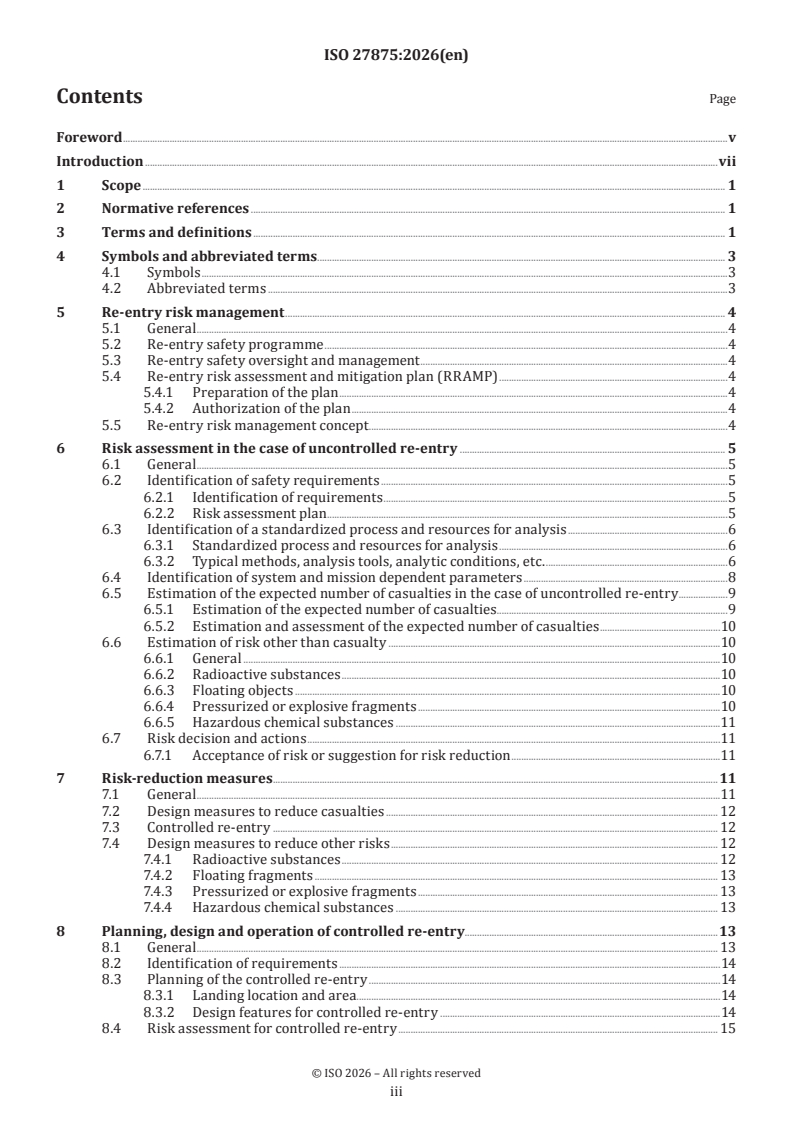
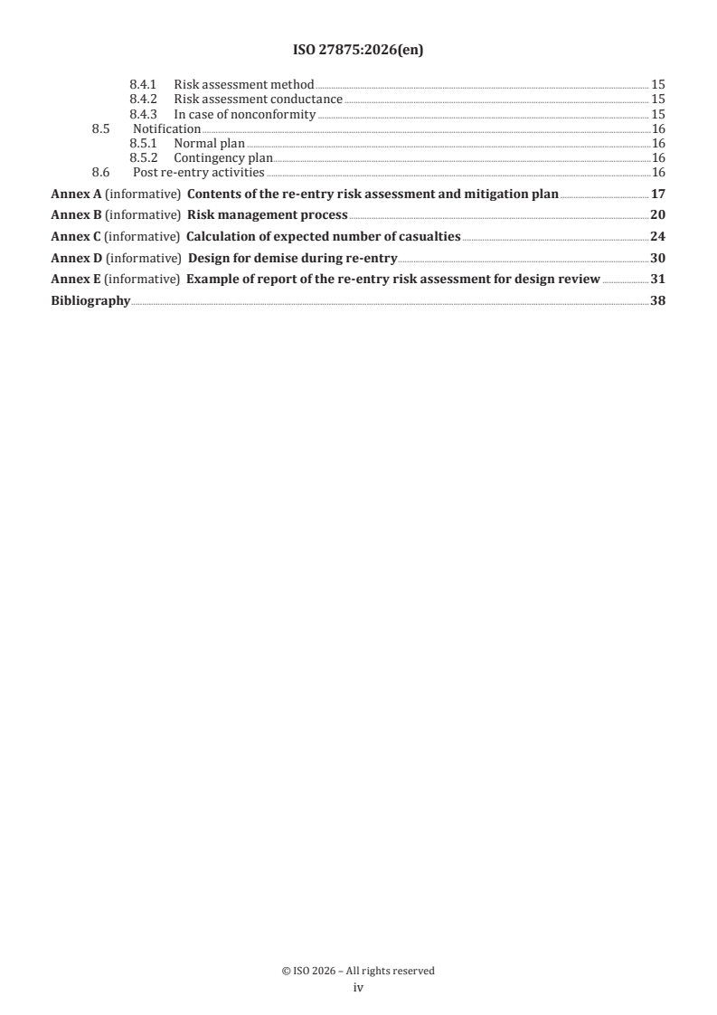
The document is organized into clauses on scope, normative references, terms and definitions, symbols and abbreviated terms, re-entry risk management, uncontrolled re-entry risk assessment, risk-reduction measures, and planning, design and operation of controlled re-entry. Annexes A to E provide supporting material for the RRAMP, the risk process, casualty calculations, design for demise, and an example report.
| Annex | What it covers |
|---|---|
| Annex A | Contents of the re-entry risk assessment and mitigation plan |
| Annex B | Risk management process |
| Annex C | Calculation of expected number of casualties |
| Annex D | Design for demise during re-entry |
| Annex E | Example report of the re-entry risk assessment for design review |
What are the key requirements of ISO 27875:2026?
Re-entry risk management setup
ISO 27875:2026 requires re-entry risk management to follow ISO 17666, with a re-entry safety programme added to the normal safety activities from ISO 14620-1. The programme is used to minimize damage and injuries and to trigger corrective actions when risks exceed safety requirements.
A re-entry risk assessment and mitigation plan (RRAMP) shall be prepared, updated through the project life cycle, approved by the safety representative, project management, and customers, and kept as part of the safety data package. In practice, this means the project needs a living plan that ties each requirement to analyses, reviews and schedules.
Safety representatives shall be appointed with authority to review safety assessments, stop hazardous activities, and endorse progression to the next phase. If requirements cannot be met, the document calls for deviation or waiver handling and disposal in accordance with ISO 14620-1.
Assessing uncontrolled re-entry
For uncontrolled re-entry, the document requires identification of re-entry safety requirements, analysis methods, system- and mission-dependent data, risk estimation, and risk decisions. Requirements from contract, voluntary commitments, and authorities shall be identified and, where possible, quantified with threshold parameters.
The analysis process shall use designated methods, tools, models, and material properties. Clause 6.3.2 sets out the general procedure from the re-entry interface point through structural breakup, survivability analysis, and estimation of the expected number of casualties. In practice, teams need to trace which components can survive heating and breakup, then assess what they can hit on the ground.
The document also requires enough system data to support the analysis: physical, aerodynamic and thermal properties; orbital conditions; detailed component descriptions; and properties of small objects that may survive and be hazardous. That matters because the casualty result depends on what actually survives, how it breaks up, and where it can land.
Estimating casualties and other risks
ISO 27875:2026 requires survivability analysis to produce a list of surviving objects and their ground impact. The expected number of casualties is then estimated using the casualty area, the landing zone defined by orbital inclination, and population density.
The document also requires assessment of risks other than casualty when relevant hazards are present. These include radioactive substances, floating objects, pressurized or explosive fragments, and hazardous chemical substances. For a reader, this means the assessment is not limited to injury numbers - it also covers ship hazards, pollution, and radioactive or toxic release.
The risk decision step requires acceptance of the design and operations or additional risk reduction actions. For uncontrolled re-entry, likelihood is treated as fixed because impact to Earth is unavoidable, so the casualty result drives the risk picture.
Reducing risk and planning controlled re-entry
If the uncontrolled re-entry risk is too high, the document calls for design measures to reduce survivability and debris casualty area, and for controlled re-entry when needed. Controlled re-entry shall aim surviving fragments at a designated area, with landing location, landing area, predicted footprint, and notifications planned in advance.
The controlled re-entry requirements include defining applicable national and regulatory requirements, ensuring the planned landing area is wider than the predicted footprint, and obtaining permission where the area is under national jurisdiction. The vehicle, ground segment, and operator shall all support the re-entry sequence, monitoring, and interruption if needed.
If controlled re-entry cannot meet the risk requirement, the document requires redesign or improved reliability of operational and disposal functions. It also allows a second-best operational strategy that targets surface routes with small land areas and few inhabitants when a controlled re-entry is not achievable.
What terms does ISO 27875:2026 define?
- Controlled re-entry - a re-entry where the time is controlled enough that surviving debris is confined to a designated area, usually an uninhabited one.
- Expected number of casualties - the predicted number of people killed or seriously injured by a re-entry, per project or programme.
- Footprint - the envelope of predicted impact points of surviving objects.
- Likelihood - the classified probability of a severe event caused by re-entry, with example levels from minimum to maximum.
- Risk index - a score combining severity and likelihood to express the size of a risk scenario.
- Risk magnitude - the risk category used to decide what action is needed, such as very high, high, medium, low, or very low.
- Severity - the classification of the consequence of re-entry, including human safety, cost impacts, and related effects.
- Lumped mass approach - a simplified survivability analysis method that treats objects as simple solids with simplified structural and thermal properties.
Who uses ISO 27875:2026?
ISO 27875:2026 is used by developers, manufacturers, space service providers, satellite operators, and launch service providers. It is also used by safety representatives, mission assurance teams, design review boards, and operations teams.
These users apply it when defining re-entry requirements, building the RRAMP, running survivability and casualty analyses, deciding between uncontrolled and controlled re-entry, and preparing notifications and post-re-entry actions. It is also relevant to organizations that need to coordinate with national authorities, civil aviation, maritime services, and other stakeholders affected by the predicted footprint.
What changed in ISO 27875:2026 from the previous edition?
ISO 27875:2026 is the third edition and cancels and replaces ISO 27875:2019 and ISO 27875:2019/Amd 1:2020. The foreword lists these main changes:
- a fuller description of the overall analysis process was added
- Earth model and atmospheric model selection was added for controlled and uncontrolled re-entry cases
- additional risk factors were added for radioactive substances, floating objects, pressurized or explosive objects, and hazardous chemical substances
- design measures to reduce those additional risks were added
- Annex B was revised for a more detailed description
- Annex C was expanded with an explanation and chart for expected number of casualties per unit casualty area
- Annex D was added for design for demise during re-entry
- Annex E was added as an example report for design review
Which standards are used with ISO 27875:2026?
ISO 27875:2026 relies on two normative references:
- ISO 14620-1 - provides the system safety requirements that support the safety representative role, phase reviews, and safety data package structure.
- ISO 17666:2025 - provides the space systems risk management framework used for risk policy, scoring schemes, risk index, risk magnitude, and risk actions.
The document also points readers to ISO 14620-2:2019, ISO 23020, ISO 24113, ISO 14222, and ISO/TR 18146:2020 in clauses, notes, and the bibliography, where they contribute background on launch site safety, material testing, debris mitigation, atmospheric data, and design for demise.
What does the ISO 27875:2026 document contain?
The body of ISO 27875:2026 combines a management framework with technical analysis methods. Clause 5 covers the safety programme, oversight, RRAMP, and the basic risk concept; Clause 6 covers uncontrolled re-entry assessment; Clause 7 covers risk-reduction measures; and Clause 8 covers controlled re-entry planning, reliability, ground systems, notification, and post-re-entry actions.
Annex C contains the casualty-area and expected-casualties formulas, plus figures showing how orbital inclination and population distribution affect the result. Annex D gives practical design measures that encourage demise, such as material choice, geometry, and packaging. Annex E provides a worked example structure for a re-entry risk assessment report, including components, material data, breakout conditions, casualty estimation, and other hazards.
Relations
- Effective Date
- 19-Aug-2023
- Effective Date
- 19-Aug-2023
Get Certified
Connect with accredited certification bodies for this standard

BUREAU VERITAS Certification Germany
Bureau Veritas certification in Germany.

Element Materials Technology
Materials testing and product certification.

AQMS Ltd.
AQMS provides ISO certification to SMEs across the UK.
Sponsored listings
Frequently Asked Questions
ISO 27875:2026 is a standard published by the International Organization for Standardization (ISO). Its full title is "Space systems — Re-entry risk management for uncrewed spacecraft and launch vehicle orbital stages". This standard covers: This document provides a framework to assess, reduce and control the potential risks that spacecraft and launch vehicle orbital stages (referred to hereinafter as “space vehicles”) pose to people and the environment when those space vehicles re-enter the Earth's atmosphere and impact the Earth’s surface. It applies to the planning, design and review of space vehicle missions for which controlled or uncontrolled re-entry is inevitable. This document applies to the following objects when assessing their risk to the ground: objects re-entering from orbit; launch vehicles (including payloads, other objects separated during the ascent phase, etc.) that are mentioned in flight safety activities under ISO 14620-2:2019[1], 6.2; interplanetary spacecraft returning to Earth. This document does not apply to systems with wings and control functions intended for targeted landing. This document assumes that the main specifications and operational procedures for ensuring safety on the ground against the re-entry of spacecraft containing radioactive material have already been determined in the mission requirements definition stage, system definition stage, operational concept definition stage, etc. Therefore, apart from matters related to re-entry safety, the main parts of the mission design and operational concept of spacecraft containing radioactive material are outside the scope of this standard.
This document provides a framework to assess, reduce and control the potential risks that spacecraft and launch vehicle orbital stages (referred to hereinafter as “space vehicles”) pose to people and the environment when those space vehicles re-enter the Earth's atmosphere and impact the Earth’s surface. It applies to the planning, design and review of space vehicle missions for which controlled or uncontrolled re-entry is inevitable. This document applies to the following objects when assessing their risk to the ground: objects re-entering from orbit; launch vehicles (including payloads, other objects separated during the ascent phase, etc.) that are mentioned in flight safety activities under ISO 14620-2:2019[1], 6.2; interplanetary spacecraft returning to Earth. This document does not apply to systems with wings and control functions intended for targeted landing. This document assumes that the main specifications and operational procedures for ensuring safety on the ground against the re-entry of spacecraft containing radioactive material have already been determined in the mission requirements definition stage, system definition stage, operational concept definition stage, etc. Therefore, apart from matters related to re-entry safety, the main parts of the mission design and operational concept of spacecraft containing radioactive material are outside the scope of this standard.
ISO 27875:2026 is classified under the following ICS (International Classification for Standards) categories: 49.140 - Space systems and operations. The ICS classification helps identify the subject area and facilitates finding related standards.
ISO 27875:2026 has the following relationships with other standards: It is inter standard links to ISO 27875:2019, ISO 27875:2019/Amd 1:2020. Understanding these relationships helps ensure you are using the most current and applicable version of the standard.
ISO 27875:2026 is available in PDF format for immediate download after purchase. The document can be added to your cart and obtained through the secure checkout process. Digital delivery ensures instant access to the complete standard document.
Standards Content (Sample)
International
Standard
ISO 27875
Third edition
Space systems — Re-entry risk
2026-07
management for uncrewed
spacecraft and launch vehicle
orbital stages
Systèmes spatiaux — Gestion du risque de la rentrée
atmosphérique pour les engins spatiaux sans équipage et les
étages orbitaux de lanceurs
Reference number
© ISO 2026
All rights reserved. Unless otherwise specified, or required in the context of its implementation, no part of this publication may
be reproduced or utilized otherwise in any form or by any means, electronic or mechanical, including photocopying, or posting on
the internet or an intranet, without prior written permission. Permission can be requested from either ISO at the address below
or ISO’s member body in the country of the requester.
ISO copyright office
CP 401 • Ch. de Blandonnet 8
CH-1214 Vernier, Geneva
Phone: +41 22 749 01 11
Email: copyright@iso.org
Website: www.iso.org
Published in Switzerland
ii
Contents Page
Foreword .v
Introduction .vii
1 Scope . 1
2 Normative references . 1
3 Terms and definitions . 1
4 Symbols and abbreviated terms. 3
4.1 Symbols .3
4.2 Abbreviated terms .3
5 Re-entry risk management . 4
5.1 General .4
5.2 Re-entry safety programme .4
5.3 Re-entry safety oversight and management .4
5.4 Re-entry risk assessment and mitigation plan (RRAMP) .4
5.4.1 Preparation of the plan .4
5.4.2 Authorization of the plan .4
5.5 Re-entry risk management concept . .4
6 Risk assessment in the case of uncontrolled re-entry . 5
6.1 General .5
6.2 Identification of safety requirements .5
6.2.1 Identification of requirements .5
6.2.2 Risk assessment plan . .5
6.3 Identification of a standardized process and resources for analysis .6
6.3.1 Standardized process and resources for analysis .6
6.3.2 Typical methods, analysis tools, analytic conditions, etc. .6
6.4 Identification of system and mission dependent parameters .8
6.5 Estimation of the expected number of casualties in the case of uncontrolled re-entry .9
6.5.1 Estimation of the expected number of casualties.9
6.5.2 Estimation and assessment of the expected number of casualties .10
6.6 Estimation of risk other than casualty .10
6.6.1 General .10
6.6.2 Radioactive substances .10
6.6.3 Floating objects .10
6.6.4 Pressurized or explosive fragments .10
6.6.5 Hazardous chemical substances .11
6.7 Risk decision and actions .11
6.7.1 Acceptance of risk or suggestion for risk reduction .11
7 Risk-reduction measures . .11
7.1 General .11
7.2 Design measures to reduce casualties . 12
7.3 Controlled re-entry . 12
7.4 Design measures to reduce other risks . 12
7.4.1 Radioactive substances . 12
7.4.2 Floating fragments . 13
7.4.3 Pressurized or explosive fragments . 13
7.4.4 Hazardous chemical substances . 13
8 Planning, design and operation of controlled re-entry.13
8.1 General . 13
8.2 Identification of requirements .14
8.3 Planning of the controlled re-entry .14
8.3.1 Landing location and area.14
8.3.2 Design features for controlled re-entry .14
8.4 Risk assessment for controlled re-entry . 15
iii
8.4.1 Risk assessment method . 15
8.4.2 Risk assessment conductance . 15
8.4.3 In case of nonconformity . 15
8.5 Notification .16
8.5.1 Normal plan .16
8.5.2 Contingency plan .16
8.6 Post re-entry activities .16
Annex A (informative) Contents of the re-entry risk assessment and mitigation plan . 17
Annex B (informative) Risk management process .20
Annex C (informative) Calculation of expected number of casualties .24
Annex D (informative) Design for demise during re-entry .30
Annex E (informative) Example of report of the re-entry risk assessment for design review .31
Bibliography .38
iv
Foreword
ISO (the International Organization for Standardization) is a worldwide federation of national standards
bodies (ISO member bodies). The work of preparing International Standards is normally carried out through
ISO technical committees. Each member body interested in a subject for which a technical committee
has been established has the right to be represented on that committee. International organizations,
governmental and non-governmental, in liaison with ISO, also take part in the work. ISO collaborates closely
with the International Electrotechnical Commission (IEC) on all matters of electrotechnical standardization.
The procedures used to develop this document and those intended for its further maintenance are described
in the ISO/IEC Directives, Part 1. In particular, the different approval criteria needed for the different types
of ISO documents should be noted. This document was drafted in accordance with the editorial rules of the
ISO/IEC Directives, Part 2 (see www.iso.org/directives).
ISO draws attention to the possibility that the implementation of this document may involve the use of (a)
patent(s). ISO takes no position concerning the evidence, validity or applicability of any claimed patent
rights in respect thereof. As of the date of publication of this document, ISO had not received notice of (a)
patent(s) which may be required to implement this document. However, implementers are cautioned that
this may not represent the latest information, which may be obtained from the patent database available at
www.iso.org/patents. ISO shall not be held responsible for identifying any or all such patent rights.
Any trade name used in this document is information given for the convenience of users and does not
constitute an endorsement.
For an explanation of the voluntary nature of standards, the meaning of ISO specific terms and expressions
related to conformity assessment, as well as information about ISO's adherence to the World Trade
Organization (WTO) principles in the Technical Barriers to Trade (TBT), see www.iso.org/iso/foreword.html.
This document was prepared by Technical Committee ISO/TC 20, Aircraft and space vehicles, Subcommittee
SC 14, Space systems and operations.
This third edition cancels and replaces the second edition (ISO 27875:2019), which has been technically
revised. It also incorporates the Amendment ISO 27875:2019/Amd 1:2020.
The main changes are as follows:
— a description explaining the entire analysis process has been added (6.3.2.1);
— a description for the selection of the Earth model and the atmospheric model has been added corresponding
to the difference of controlled or uncontrolled re-entry (6.3.2.2);
— adding to the expected number of casualties, the following risk factors have been newly added (6.6 and
7.1) and design measures to reduce each risk have been described (7.4):
— radioactive substances;
— floating objects;
— pressurized or explosive objects;
— hazardous chemical substances;
— in Annex B, for a more detailed description, Table B.1 has been revised;
— in Annex C, an explanation for the “Expected number of casualties per unit casualty area as an example”
has been added with a chart (Figure C.4);
— a design for demise during re-entry has been added as Annex D;
— an “Example of report of the re-entry risk assessment for design review” has been added as Annex E.
v
Any feedback or questions on this document should be directed to the user’s national standards body. A
complete listing of these bodies can be found at www.iso.org/members.html.
vi
Introduction
Under international space treaties, the “launching state” is liable for damage or injuries caused by uncrewed
spacecraft and launch vehicle orbital stages that re-enter the Earth's atmosphere. In addition, commercial
operators are subject to the national safety regulations or laws of the launching country that relate to the
re-entry of spacecraft and launch vehicle orbital stages. To minimize damages and injuries caused by re-
entering spacecraft and launch vehicle orbital stages, all parties (i.e. developers, manufacturers, space
service providers, satellite operators and launch service providers) should take preventive measures during
design and operations.
[2]
NOTE Useful background information for this document is available in ISO 24113 .
vii
International Standard ISO 27875:2026(en)
Space systems — Re-entry risk management for uncrewed
spacecraft and launch vehicle orbital stages
1 Scope
This document provides a framework to assess, reduce and control the potential risks that spacecraft and
launch vehicle orbital stages (referred to hereinafter as “space vehicles”) pose to people and the environment
when those space vehicles re-enter the Earth's atmosphere and impact the Earth’s surface. It applies to
the planning, design and review of space vehicle missions for which controlled or uncontrolled re-entry is
inevitable.
This document applies to the following objects when assessing their risk to the ground:
a) objects re-entering from orbit;
b) launch vehicles (including payloads, other objects separated during the ascent phase, etc.) that are
[1]
mentioned in flight safety activities under ISO 14620-2:2019 , 6.2;
c) interplanetary spacecraft returning to Earth.
This document does not apply to systems with wings and control functions intended for targeted landing.
This document assumes that the main specifications and operational procedures for ensuring safety on the
ground against the re-entry of spacecraft containing radioactive material have already been determined
in the mission requirements definition stage, system definition stage, operational concept definition stage,
etc. Therefore, apart from matters related to re-entry safety, the main parts of the mission design and
operational concept of spacecraft containing radioactive material are outside the scope of this standard.
2 Normative references
The following documents are referred to in the text in such a way that some or all their content constitutes
requirements of this document. For dated references, only the edition cited applies. For undated references,
the latest edition of the referenced document (including any amendments) applies.
1)
ISO 14620-1 , Space systems — Safety requirements — Part 1: System safety
ISO 17666:2025, Space systems — Programme management — Risk management
3 Terms and definitions
For the purposes of this document, the following terms and definitions apply.
ISO and IEC maintain terminology databases for use in standardization at the following addresses:
— IEC Electropedia: available at https:// www .electropedia .org/
— ISO Online browsing platform: available at https:// www .iso .org/ obp
1) Under preparation. Stage at the time of publication: ISO/FDIS 14620-1:2026.
3.1
controlled re-entry
type of re-entry where the time of re-entry is sufficiently controlled so that the impact of any surviving
debris on the surface of the Earth is confined to a designated area
Note 1 to entry: The designated area is usually an uninhabited region, such as an ocean.
3.2
expected number of casualties
number of people who are predicted to be killed or seriously injured by the re-entry, per project or
programme
Note 1 to entry: The calculation of the expected number of casualties (3.2) is complex. Organizations use different
processes to estimate it based on methods deemed applicable by the organizations (see 6.5.1 and Annex C).
Note 2 to entry: The medical profession has defined several different injury-scoring systems to distinguish the severity
(3.8) of an injury. Broadly, a serious injury is one of such severity (3.8) that hospitalization is required.
Note 3 to entry: Typically, the assessment of the expected number of casualties (3.2) is conducted at every re-entry
event. However, in the case of a system disintegrated into multiple sub-systems that would independently cause re-
entry, the approving agent authority requires assessing the total expected number of casualties (3.2) of all re-entering
objects.
3.3
footprint
envelope of predicted impact points of surviving objects
3.4
likelihood
classification of probability of occurrence of severe events caused by re-entry, classified as “maximum”,
“high”, “medium”, “low” and “minimum”, as examples
Note 1 to entry: This term is used in the classification of the probability of occurrence of severe events from the re-
entry event.
Note 2 to entry: The definition of this term has been derived from ISO 17666: 2025, 5.2.2 e), Table 2.
3.5
lumped mass approach
one of the typical methods for the survivability analysis to attain the better cost performance effect
that assumes the simplified structural and thermal property for simple trajectory, aerodynamic,
aerothermodynamic and thermal analyses
Note 1 to entry: This term is used in the re-entry survivability analysis.
Note 2 to entry: The objects are treated as simple solid objects, or combination of multiple layered solid objects. For
details, see 6.3.2.2 a).
3.6
risk index
index for scoring schemes for the risk assessment, defined from a combination of the severity (3.8) of the
consequences and the likelihood (3.4) of the occurrence to denote the risk magnitude (3.7) of the various risk
scenarios
Note 1 to entry: The definition of this term has been derived from ISO 17666: 2025, 5.2.1.2 e) and f).
3.7
risk magnitude
criteria to determine the actions to be taken regarding risks and the decision level related to the associated
risk in the project structure based on the risk index and classified with “very high level”, “high risk”, “medium
risk”, “low risk” and “very low risk”
Note 1 to entry: The definition of this term has been derived from ISO 17666: 2025, 5.2.1.2 g) and Figure 3.
3.8
severity
classification of the negative consequences caused by re-entry in terms of cost impacts, human safety, etc.,
when the risk occurs and is categorised as “catastrophic”, “critical”, “major”, “significant” and “negligible”
Note 1 to entry: This term is used in the classification of the negative consequences of the re-entry events.
Note 2 to entry: The definition of this term has been derived from ISO 17666: 2025, 5.2.1.2 e), Table 1.
4 Symbols and abbreviated terms
4.1 Symbols
E expected number of casualties (see 6.3.2)
c
P probability of impact
i
A casualty area
c
A projected area of fallen objects
d
r radius of projected area of fallen objects
d
r radius of a standing individual
h
A cross-sectional area of a standing individual
h
4.2 Abbreviated terms
AIP aeronautical information package
ATCM Antarctic Treaty Consultative Meeting
CFRP carbon fibre reinforced plastics
CIESIN Centre for International Earth Science Information Network
DTM Deutsche Tourenwagen Masters
G7 Group of Seven
GGP gridded global population distribution of the world
GPW gridded population of the world
GRAM global reference atmospheric model
ICAO International Civil Aviation Organization
NAVAREA navigational area
NOTAM notice to airmen
NOTMAR notice to mariners
RRAMP re-entry risk assessment and mitigation plan
TCBMs transparency and confidence-building measures
UNESCO United Nations Educational, Scientific and Cultural Organization
5 Re-entry risk management
5.1 General
Re-entry risk management shall be conducted according to ISO 17666, which is briefly explained in Annex B.
This document mainly focuses on the estimation of the risk of casualty and, partly, on ground pollution. This
also presents requirements for when controlled re-entry would be conducted to reduce risk.
5.2 Re-entry safety programme
In addition to the safety activities required by ISO 14620-1:—,4.4, a re-entry safety programme shall be
established to ensure:
a) minimization of damage and injuries caused by re-entering spacecraft or launch vehicle orbital stages;
b) suggestions for corrective actions regarding risks assessed as exceeding safety requirements.
5.3 Re-entry safety oversight and management
In accordance with ISO 14620-1:— 4.3, safety representatives shall be appointed. Safety representatives
shall be responsible for safety activities, have the right to access related data and be authorised to reject
any project document, stop any project activities, or interrupt hazardous operations. In accordance with
ISO 14620-1:—, 4.4, at each design or operation phase, a safety representative shall review the result of the
safety assessment, review the plan for the next phase and endorse the decision to proceed to the following
phase. If there are requirements that cannot be met, a request for deviation or a waiver is generated and
reviewed, and the space vehicle shall be disposed of in accordance with ISO 14620-1:—, 4.10.6.
5.4 Re-entry risk assessment and mitigation plan (RRAMP)
5.4.1 Preparation of the plan
A RRAMP shall be prepared and updated throughout the project life cycle as part of the safety data package
specified in ISO 14620-1:—,4.10.5.
The RRAMP defines the work plan corresponding to each requirement in this document and detailed
schedules for critical activities (design, analysis and testing reviews) throughout the life of the project.
Typical contents of the RRAMP are given in Annex A.
5.4.2 Authorization of the plan
The RRAMP shall be approved by the safety representative, the head of project management and the
customers. The RRAMP is changed and evolved as the project progresses.
5.5 Re-entry risk management concept
The scoring schemes for the severity of consequence of re-entry hazards are defined by the national
authority. Risk is assessed by the risk magnitude expressed as the combination of its severity and likelihood
(see Annex B and ISO 17666:2025).
The scoring is typically related to the casualty area (see 6.5.1.2) in the case of casualty risk, damage
of properties in the case of social risk, or pollution on the ground in the case of environmental risk (see
Table B.1 or ISO 17666:2025, Table 1). Generally, a risk index is defined as a combination of severity and
likelihood, and a risk magnitude is defined for each risk index.
For assessing re-entry risk:
a) In the case of uncontrolled re-entry, the expected number of casualties is calculated as a function of
the casualty area, orbital inclination and population density. Since falling to the ground is unavoidable,
likelihood, as one factor of the risk index, is fixed at 1,0, and the risk index is equivalent to the rest of
the factor severity presented by the expected number of casualties (see Table B.2 or ISO 17666:2025,
Table 1). Subclause 6.5 describes assessment procedures for casualty risk in the case of uncontrolled re-
entry and 6.6 for environmental risk.
b) In the case of controlled re-entry, the expected number of casualties is calculated in the same manner
as for the uncontrolled re-entry (i.e. a function of the casualty area, orbital inclination and population
density), but the expected number of casualties is weighted by the reliability of functions and
sufficiency of propellants needed for controlling the re-entry. See Table B.1 or ISO 17666:2025, Figure 1.
Subclause 8.4 describes the assessment procedures for the risk of casualty in the case of controlled re-
entry.
[2]
NOTE ISO 24113 :2023, 7.3.4.3 presents the limit of the expected number of casualties per re-entry of a
spacecraft or launch vehicle orbital stage.
Proposed actions may be defined for each risk magnitude (see Tables B.3 and B.4 or ISO 17666: 2025,
Figure 3 and Table 3).
6 Risk assessment in the case of uncontrolled re-entry
6.1 General
A safety assessment shall be conducted to evaluate the risks associated with an uncontrolled re-entry and to
determine the need for design improvements or a controlled re-entry. The safety assessment should include
the following:
a) identification of the safety requirements;
b) identification of a standardized process and resources for analysis;
c) identification of system-dependent parameters (e.g. hardware design parameters) and mission
dependent parameters, such as orbital parameters, decaying trajectory parameters, etc.);
d) estimation of risk;
e) risk decision and actions.
NOTE Because the general concept for risk assessment is given in ISO 17666, this clause supplements specific
requirements related to re-entry using terms (risk scenario, risk magnitude, risk decision and actions, etc.) defined in
ISO 17666.
6.2 Identification of safety requirements
6.2.1 Identification of requirements
Specific re-entry safety requirements imposed contractually, voluntarily, or by national or international
authorities shall be identified, and where possible, quantified with threshold parameters.
6.2.2 Risk assessment plan
Re-entry risk assessment actions (analyses, reports, etc.) shall be defined and scheduled. Additionally,
a conformance matrix shall be maintained. The matrix correlates safety requirements with the system
design and operation plan, which includes quantitative results achieved, threshold values, consequences for
violating thresholds, and the probability that those consequences are realized.
The expected output is the assessment parameters (e.g. risk to people on the ground and its associated
mathematical parameters) and their thresholds, or the concept for risk decision and the actions according to
the severity of consequences and the likelihood of occurrence.
NOTE 1 Several national governments and space agencies adopt 0,000 1 persons as an acceptable upper limit for
the expected number of casualties.
NOTE 2 Generally, on-board radioactive substances, toxic substances and any other hazardous materials are
considered when evaluating and limiting the potentially adverse effects of re-entry on the Earth’s environment.
6.3 Identification of a standardized process and resources for analysis
6.3.1 Standardized process and resources for analysis
A standardized process to identify the safety requirements established by national or international
authorities shall be implemented by the entity which conducts the analysis. The standardized process shall
designate methods, tools, models, physical characteristics and properties of materials, as shown in 6.3.2.
6.3.2 Typical methods, analysis tools, analytic conditions, etc.
6.3.2.1 General procedure
a) In the case of uncontrolled re-entry, trajectory and thermal analyses start from the “re-entry interface
point”, where the atmospheric density increases to generate aerodynamic heating (typically defined at
120 km of altitude). At that point, deployment devices are separated by the aerodynamic drag force.
When decaying down below approximately 100 km, the structural breakup of the space system, due
to the thermal effect and aerodynamic drag force, begins. In this document, this point is called the
initial structural breakup point. Most of the governmental space agencies in the spacefaring nations
have assumed that this break-up point is at an altitude of 78 km, as a de-facto value, unless it can be
determined on technical grounds that can be defined in another way. At this point, it is assumed that
all the components are separated from the parent body. When a certain component is installed inside
another, such component is assumed to be thrown to the outer stream when the original component
experiences structural break-up (known as the second break-up point). A survivability analysis for each
component shall follow to identify the objects that can survive re-entry.
b) In the case of controlled re-entry, the time and location of the “envelope of predicted impact points
of surviving objects” (referred to as “footprint”) shall be planned, and a re-entry manoeuvre shall
be conducted according to the plan. The trajectory analysis starts at the end of the final re-entry
manoeuvre, and thermal analysis continues from the point where aerodynamic heating can be expected.
The analysis shall proceed in the same way as for an uncontrolled re-entry.
c) The survivability analysis shall be followed by an estimation of the expected number of casualties and
shall include a risk assessment for other hazards (e.g. radioactive substances, floating objects, explosion
of surviving objects and the environmental pollution from chemical substances).
d) The results of the procedures, listed in a), b) and c), shall be used to develop the total expected number
of casualties, which covers all the re-entry objects predicted to survive, plus an assessment of other
hazards described in c). The typical contents of the report of the re-entry risk assessment for the design
review are given in Annex E.
6.3.2.2 Analysis tools, models and approaches
Analysis tools, models and approaches include the following:
a) algorithms for trajectory, aerodynamic, aerothermodynamic, and thermal analyses for re-entry
trajectory and thermal analyses;
NOTE 1 There is the lumped mass approach, a typical method of the survivability analysis to attain the better
cost performance effect that assumes the simplified structural and thermal property for simple trajectory,
aerodynamic, aerothermodynamic and thermal analyses. When analysing the survivability of space systems,
conducting precise analyses of hundreds of elements with diverse structural characteristics, such as electronic
devices, mechanical devices and high-pressure vessels, can be a significant financial and time burden. A method
can be used in which objects are treated as one of several simple shapes, rough dimensions, mass and material
constitutions, which means applying standardized aerodynamic and thermal properties (e.g. aerodynamic
drag coefficient and coefficients for average heating) according to the shapes and attitude during re-entry,
respectively. Objects are treated as single solid objects, ignoring temperature gradient within a material and
average temperature corresponding to the absorbed heat, as long as remediation methods, applying multiple
layered structure or effect of surface peeling after reaching the melting temperature, etc., are not applied. Each
object is determined to be demised when the absorbed heat reaches the amount of heat required to demise it. This
method ignores changes in the object's mass, dimensions and shape during heating, so that the results tend to be
optimistic due to ignoring changes in shape and dimension, and reduction of the radiation effect form the surface
to the outer space, etc.
b) requisite physical characteristics, aerodynamic properties, and thermal properties for trajectory and
thermal analyses;
NOTE 2 Physical characteristics and properties are given by the authority of the system designers or national
[3]
authorities. ISO 23020 provides the test method to obtain physical properties of materials or components for
break-up models.
c) Earth model and atmospheric model;
For both controlled and uncontrolled re-entry, the effects, due to the time-dependent, location-
dependent or altitude-dependent differences of values in the Earth and atmospheric models,
are observed in the results of the re-entry analysis. Unignorable effects are particularly
observed in the case of controlled re-entry. Application of these models may be selected as
shown in Table 1, depending on the characteristics of systems and descending trajectories.
However, the error caused by differences in Earth’s gravity and the physical characteristics
of the atmosphere shall be adequately assessed, and enough margins shall be ensured.
Table 1 — Applicable Earth models and atmospheric models
Controlled re-entry Uncontrolled re-entry
Earth model A detailed Earth model (considering the non-spherical Perfect sphere or the detailed model (when
component of the Earth's gravity), defined with applying the detailed model, the worst-case
latitude of the re-entry interface point, in
a) Earth's equatorial radius;
which minimum amount of heat absorption
b) Earth's gravitational constant;
is obtained).
c) zonal harmonic function J2 term;
d) zonal harmonic function J3 term;
e) zonal harmonic function J4 term.
as example.
Atmospheric A model to describe the variations in atmospheric A model to describe the average value of at-
model density and pressure with location and altitude should mospheric density and pressure.
be used. The JB2008, Earth GRAM 2010 or DTM-2009
If the uncertainty from the average value of
models may be used for altitudes above 120 km, while
atmospheric density and pressure could be
NRLMSISE-00 or Earth GRAM 2010 should be used below
obtained, considering the prospected re-entry
for altitudes below 120 km altitude. See ISO 14222 for
timing, the uncertainty of the expected number
further details.
of casualties could be assessed. See ISO 14222
for further details.
d) any constants or formulae for perturbations on the decaying trajectory;
e) human population distribution model (see Clause C.5);
f) definition of casualty area (see 6.5.1.2.1 for a typical definition of casualty area);
g) reduction in mass, size and deformation due to ablation during re-entry;
h) definition of the techniques and assumptions used to estimate the expected number of casualties (e.g.
year of re-entry, population model and casualty area).
6.3.2.3 Analysis conditions, assumptions or criteria for assessment
Due to the complexity of re-entry physics and material responses, detailed analyses are necessary to
obtain accurate estimates of aerodynamic and thermal phenomena. If there are technical uncertainties or
insufficient resources, then simplified models, analysis conditions, criteria or assumptions are applied.
The following conditions are assumed, for example:
a) attitude mode (e.g. tumbling, side-on stable);
NOTE 1 Depending on the functions of the tool, but in case that the actual attitude is unknown, random
tumbling mode is selected. However, “broadside and spinning motion” is applied to the long rod, and “end-on and
spinning motion” can be applied to a thin circular plate.
b) contribution of oxidation to the heating rate;
NOTE 2 There is no standardized value for the oxidation efficiency. However, since the effect is expected,
ignoring it seems to be too conservative. Usually, it is assumed to be 0,4 or 0,5.
c) standard conditions of the structural break-up process and sequence (e.g. de facto altitude of the
aerodynamic and thermal break-up point, where the space vehicle is assumed to be disjoined into a set
of components, a specific value acquired from the analysis);
NOTE 3 For complex systems where the specific value of the structural breakup point cannot be obtained
from the analysis, the altitude of the breakup point is widely assumed to be 78 km based on observational data.
There have been other attempts to monitor the impact of break-up with on-board sensors. In the case of a simple
structure, such as a propellant tank, the structural break-up point is estimated with a thermal analysis.
d) initial temperature, when the analysis starts;
NOTE 4 In most of the space agencies in the spacefaring nations, 300 K tends to be applied.
e) criteria for eliminating any components from the risk analyses due to their low survivability;
NOTE 5 In the usual on-board electric and electronic components, the mass of the structure panels, which
potentially stand for heating and survive re-entry, occupies just 30 % to 40 % of the total mass. The residual mass
is occupied by semi-conductors, wire harnesses and non-metallic plates that can demise easily. So, it is reasonable
to determine to demise the component when it absorbs 30 % to 40 % of the latent heat of fusion of the component,
and structure panels demise or scatter.
NOTE 6 A wire harness that is longer than 1 m demises during normal re-entry, whereas a harness that is
shorter than 1 m does not reach minimum impact energy if it survives.
f) threshold for minimum impact energy that causes casualty.
NOTE 7 Many space agencies in the spacefaring nations have agreed that the threshold for minimum impact
energy that causes casualty is 15 J.
6.4 Identification of system and mission dependent parameters
The following data shall be obtained from those organizations that are responsible for the design or
operation of a space vehicle:
a) system-dependent parameters, including the object’s physical characteristics, aerodynamic properties
and thermal properties;
b) mission-dependent parameters, including orbital characteristics which define the initial point of re-
entry analysis;
c) detailed characteristics of the space vehicle including its components (e.g. propellant tanks, pressurized
vessels, major structural elements), as well as their architecture, mass, materials, dimensions, shapes,
connectivity, mutual shielding and nesting, and other factors (e.g. aerodynamic drag coefficient and
coefficients for average heating.);
NOTE 1 Design data for deployment devices enable better estimation of the break-up point.
NOTE 2 It is important to list all the components which are released when the space vehicle experiences break-
up during re-entry. This is particularly the case for any components possibly surviving re-entry, and which have
an impact energy on the ground that can go beyond the criteria defined in 6.3.2.3, f).
d) properties of small and potentially surviving and hazardous objects that are likely to be released during
re-entry.
6.5 Estimation of the expected number of casualties in the case of uncontrolled re-entry
6.5.1 Estimation of the expected number of casualties
6.5.1.1 Survivability analysis
A survivability analysis shall be conducted in accordance with 6.3 and 6.4 to confirm conformity with the
requirements in 6.2, and its result of the analysis shall include a list of objects that survive re-entry and
impact on the ground.
6.5.1.2 Casualty area
6.5.1.2.1 Definition of casualty area
To estimate the expected number of casualties, the area of the fall zone, where a falling object could
potentially make “dangerous contact” with a human on the ground, is calculated as the “casualty area
(quantified by Ac).” If the falling object is spherical, the casualty area is calculated by adding the radius of
the cross-sectional area of the falling
...