


ISO/CD 6789-1.3
(Main)Assembly tools for screws and nuts — Hand torque tools — Part 1: Requirements and methods for design conformance testing and quality conformance testing: minimum requirements for declaration of conformance
Assembly tools for screws and nuts — Hand torque tools — Part 1: Requirements and methods for design conformance testing and quality conformance testing: minimum requirements for declaration of conformance
This document specifies the conformance testing and marking requirements for hand torque tools used for controlled tightening of screws and nuts. It also specifies the minimum requirements for a manufacturer’s declaration of conformance for hand torque tools. This document applies to hand torque tools which are classified as indicating torque tools (Type I) and setting torque tools (Type II). NOTE Hand torque tools covered by this document are those identified in ISO 1703:2018 by reference numbers 7 1 00 01 0 to 7 1 00 14 0 inclusive. Torque limiting hand torque tools do not yet have reference numbers and will not do so until the next revision of ISO 1703 This document does not specify requirements of calibration certificates for hand torque tools. These are described in ISO 6789‑2. This document does not specify requirements for verifying the performance of hand torque tools. These are described in ISO 6789-3.
Outils de manoeuvre pour vis et écrous — Outils dynamométriques à commande manuelle — Partie 1: Exigences et méthodes d'essai pour vérifier la conformité de conception et la conformité de qualité: exigences minimales pour déclaration de conformité
ISO 6789-1:2017 spécifie les exigences d'essai de conformité et de marquage relatives aux outils dynamométriques à commande manuelle utilisés pour le serrage contrôlé de vis et écrous. Elle spécifie également les exigences minimales relatives à la déclaration de conformité des outils dynamométriques à commande manuelle. ISO 6789-1:2017 s'applique aux outils dynamométriques à commande manuelle classés en tant qu'outils dynamométriques à lecture directe (Type I) et outils dynamométriques à déclenchement (Type II). NOTE Les outils dynamométriques à commande manuelle couverts par le présent document sont ceux identifiés dans l'ISO 1703:2005 sous les numéros de référence 6 1 00 11 0, 6 1 00 11 1 et 6 1 00 12 0, 6 1 00 12 1 et 6 1 00 14 0, 6 1 00 15 0. L'ISO 1703 est en cours de révision. Dans la prochaine édition, les outils dynamométriques seront traités dans un article distinct, et du fait de cette modification, les numéros de référence changeront également et des numéros de référence supplémentaires seront ajoutés. ISO 6789-1:2017 ne spécifie pas d'exigences relatives aux certificats d'étalonnage des outils dynamométriques à commande manuelle. Celles-ci sont décrites dans l'ISO 6789‑2.
General Information
- Status
- Not Published
- Technical Committee
- ISO/TC 29/SC 10 - Assembly tools for screws and nuts, pliers and nippers
- Drafting Committee
- ISO/TC 29/SC 10 - Assembly tools for screws and nuts, pliers and nippers
- Current Stage
- 3000 - Committee draft (CD) registered
- Start Date
- 17-Dec-2025
- Completion Date
- 14-Feb-2026
Relations
- Effective Date
- 12-Feb-2026
- Effective Date
- 25-Mar-2023
Overview
ISO/CD 6789-1.3 is an international draft standard developed by ISO for the reliable testing, classification, and marking of hand torque tools used with screws and nuts. This document outlines the requirements for both design conformance and quality conformance testing, as well as the minimum criteria for a manufacturer’s declaration of conformance. It applies to hand torque tools classified as indicating torque tools (Type I) and setting torque tools (Type II), as identified in ISO 1703:2018, and serves as a foundational reference for manufacturers, suppliers, and quality assurance professionals in the assembly tool sector.
Key Topics
Scope and Classification
The standard covers hand torque tools such as wrenches and screwdrivers that are designed for the controlled tightening of fasteners. It includes:- Indicating torque tools (Type I): Mechanical or electronic tools that display the torque being applied.
- Setting torque tools (Type II): Tools set to deliver a pre-selected torque value.
Design Conformance Testing
Manufacturers are required to verify and document that each tool model meets strict design criteria, including:- Maximum torque values and ranges
- specified angle range (where angle measurement is integrated)
- Scale, dial, and display requirements for clarity and resolution
- Permissible torque and angle error limits
- Endurance and overloading performance
Quality Conformance Testing
Ongoing quality checks are mandated during production to ensure that every tool meets the specified requirements from the design phase. Depending on customer needs, tools must undergo either complete calibration or performance verification according to related ISO documents.Manufacturer’s Declaration of Conformance
Every compliant torque tool model must be accompanied by a declaration confirming it has been tested and meets the requirements of ISO/CD 6789-1.3. The declaration must clearly specify tool identification, torque range, measurement accuracy, and responsible personnel.Marking Requirements
Finished tools must display clear and permanent markings that indicate the key operating parameters, manufacturer details, and relevant identification numbers for traceability and user assurance.
Applications
ISO/CD 6789-1.3 is crucial in multiple industries where the precision assembly of mechanical joints is required, including:
- Automotive manufacturing and repair
- Aerospace assembly
- Industrial equipment fabrication
- Maintenance and service operations
- Electronics and consumer product assembly
By standardizing conformance and marking, this document ensures that torque tools can be selected and used with confidence, enhancing consistent quality, traceability, and workplace safety in fastener tightening processes.
Related Standards
- ISO 6789-2: Outlines requirements for the calibration and determination of measurement uncertainty for hand torque tools-essential for accuracy verification and calibration certificate issuance.
- ISO 6789-3: Specifies performance verification requirements for torque tools in use, allowing users to periodically check tool reliability and performance.
- ISO 1703:2018: Provides classification and reference numbers for assembly tools, including those relevant to this standard.
- ISO 1173 and ISO 1174-1: Address drive end and driving square dimensions for assembly tools.
- ISO/IEC 17025: Specifies general requirements for testing and calibration laboratory competence.
Practical Value
Conforming to ISO/CD 6789-1.3 provides manufacturers and users with:
- Global alignment of product quality and testing methods
- Reliable documentation for regulatory and customer requirements
- Reduced risk of fastener failure by ensuring tool accuracy and durability
- Improved operational safety and traceability through standardized marking and declarations
This standard is fundamental for any organization involved in designing, producing, procuring, or using hand torque tools, facilitating high levels of quality control throughout the product lifecycle.
Buy Documents
ISO/CD 6789-1.3 - Assembly tools for screws and nuts — Hand torque tools — Part 1: Requirements and methods for design conformance testing and quality conformance testing: minimum requirements for declaration of conformance/9/2025
ISO/CD 6789-1.3 - Outils de manoeuvre pour vis et écrous — Outils dynamométriques à commande manuelle — Partie 1: Exigences et méthodes d'essai pour vérifier la conformité de conception et la conformité de qualité: exigences minimales pour déclaration de conformité/4/2025
Get Certified
Connect with accredited certification bodies for this standard

National Aerospace and Defense Contractors Accreditation Program (NADCAP)
Global cooperative program for special process quality in aerospace.
CARES (UK Certification Authority for Reinforcing Steels)
UK certification for reinforcing steels and construction.
DVS-ZERT GmbH
German welding certification society.
Sponsored listings
Frequently Asked Questions
ISO/CD 6789-1.3 is a draft published by the International Organization for Standardization (ISO). Its full title is "Assembly tools for screws and nuts — Hand torque tools — Part 1: Requirements and methods for design conformance testing and quality conformance testing: minimum requirements for declaration of conformance". This standard covers: This document specifies the conformance testing and marking requirements for hand torque tools used for controlled tightening of screws and nuts. It also specifies the minimum requirements for a manufacturer’s declaration of conformance for hand torque tools. This document applies to hand torque tools which are classified as indicating torque tools (Type I) and setting torque tools (Type II). NOTE Hand torque tools covered by this document are those identified in ISO 1703:2018 by reference numbers 7 1 00 01 0 to 7 1 00 14 0 inclusive. Torque limiting hand torque tools do not yet have reference numbers and will not do so until the next revision of ISO 1703 This document does not specify requirements of calibration certificates for hand torque tools. These are described in ISO 6789‑2. This document does not specify requirements for verifying the performance of hand torque tools. These are described in ISO 6789-3.
This document specifies the conformance testing and marking requirements for hand torque tools used for controlled tightening of screws and nuts. It also specifies the minimum requirements for a manufacturer’s declaration of conformance for hand torque tools. This document applies to hand torque tools which are classified as indicating torque tools (Type I) and setting torque tools (Type II). NOTE Hand torque tools covered by this document are those identified in ISO 1703:2018 by reference numbers 7 1 00 01 0 to 7 1 00 14 0 inclusive. Torque limiting hand torque tools do not yet have reference numbers and will not do so until the next revision of ISO 1703 This document does not specify requirements of calibration certificates for hand torque tools. These are described in ISO 6789‑2. This document does not specify requirements for verifying the performance of hand torque tools. These are described in ISO 6789-3.
ISO/CD 6789-1.3 is classified under the following ICS (International Classification for Standards) categories: 25.140.30 - Hand-operated tools. The ICS classification helps identify the subject area and facilitates finding related standards.
ISO/CD 6789-1.3 has the following relationships with other standards: It is inter standard links to prEN ISO 6789-1, ISO 6789-1:2017. Understanding these relationships helps ensure you are using the most current and applicable version of the standard.
ISO/CD 6789-1.3 is available in PDF format for immediate download after purchase. The document can be added to your cart and obtained through the secure checkout process. Digital delivery ensures instant access to the complete standard document.
Standards Content (Sample)
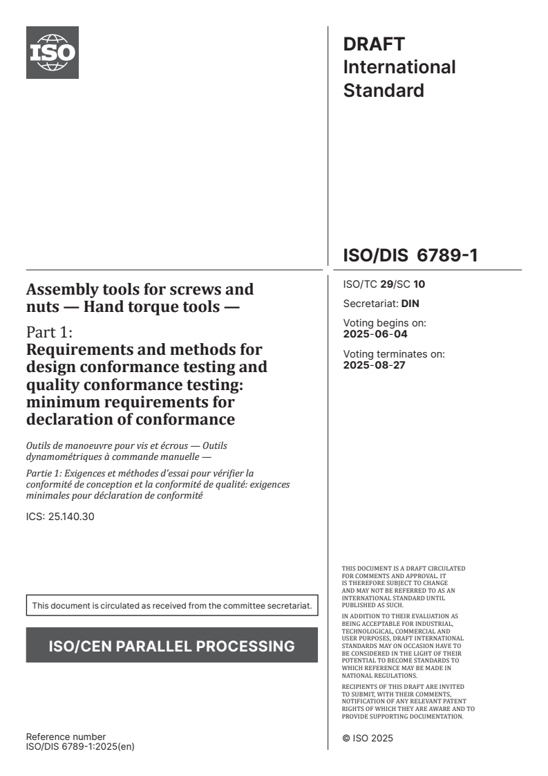
DRAFT
International
Standard
ISO/DIS 6789-1
ISO/TC 29/SC 10
Assembly tools for screws and
Secretariat: DIN
nuts — Hand torque tools —
Voting begins on:
Part 1: 2025-06-04
Requirements and methods for
Voting terminates on:
2025-08-27
design conformance testing and
quality conformance testing:
minimum requirements for
declaration of conformance
Outils de manoeuvre pour vis et écrous — Outils
dynamométriques à commande manuelle —
Partie 1: Exigences et méthodes d'essai pour vérifier la
conformité de conception et la conformité de qualité: exigences
minimales pour déclaration de conformité
ICS: 25.140.30
THIS DOCUMENT IS A DRAFT CIRCULATED
FOR COMMENTS AND APPROVAL. IT
IS THEREFORE SUBJECT TO CHANGE
AND MAY NOT BE REFERRED TO AS AN
INTERNATIONAL STANDARD UNTIL
PUBLISHED AS SUCH.
This document is circulated as received from the committee secretariat.
IN ADDITION TO THEIR EVALUATION AS
BEING ACCEPTABLE FOR INDUSTRIAL,
TECHNOLOGICAL, COMMERCIAL AND
USER PURPOSES, DRAFT INTERNATIONAL
STANDARDS MAY ON OCCASION HAVE TO
ISO/CEN PARALLEL PROCESSING
BE CONSIDERED IN THE LIGHT OF THEIR
POTENTIAL TO BECOME STANDARDS TO
WHICH REFERENCE MAY BE MADE IN
NATIONAL REGULATIONS.
RECIPIENTS OF THIS DRAFT ARE INVITED
TO SUBMIT, WITH THEIR COMMENTS,
NOTIFICATION OF ANY RELEVANT PATENT
RIGHTS OF WHICH THEY ARE AWARE AND TO
PROVIDE SUPPORTING DOCUMENTATION.
Reference number
ISO/DIS 6789-1:2025(en)
DRAFT
ISO/DIS 6789-1:2025(en)
International
Standard
ISO/DIS 6789-1
ISO/TC 29/SC 10
Assembly tools for screws and
Secretariat: DIN
nuts — Hand torque tools —
Voting begins on:
Part 1:
Requirements and methods for
Voting terminates on:
design conformance testing and
quality conformance testing:
minimum requirements for
declaration of conformance
Outils de manoeuvre pour vis et écrous — Outils
dynamométriques à commande manuelle —
Partie 1: Exigences et méthodes d'essai pour vérifier la
conformité de conception et la conformité de qualité: exigences
minimales pour déclaration de conformité
ICS: 25.140.30
THIS DOCUMENT IS A DRAFT CIRCULATED
FOR COMMENTS AND APPROVAL. IT
IS THEREFORE SUBJECT TO CHANGE
AND MAY NOT BE REFERRED TO AS AN
INTERNATIONAL STANDARD UNTIL
PUBLISHED AS SUCH.
This document is circulated as received from the committee secretariat.
IN ADDITION TO THEIR EVALUATION AS
BEING ACCEPTABLE FOR INDUSTRIAL,
© ISO 2025
TECHNOLOGICAL, COMMERCIAL AND
USER PURPOSES, DRAFT INTERNATIONAL
All rights reserved. Unless otherwise specified, or required in the context of its implementation, no part of this publication may
STANDARDS MAY ON OCCASION HAVE TO
ISO/CEN PARALLEL PROCESSING
be reproduced or utilized otherwise in any form or by any means, electronic or mechanical, including photocopying, or posting on
BE CONSIDERED IN THE LIGHT OF THEIR
the internet or an intranet, without prior written permission. Permission can be requested from either ISO at the address below
POTENTIAL TO BECOME STANDARDS TO
WHICH REFERENCE MAY BE MADE IN
or ISO’s member body in the country of the requester.
NATIONAL REGULATIONS.
ISO copyright office
RECIPIENTS OF THIS DRAFT ARE INVITED
CP 401 • Ch. de Blandonnet 8
TO SUBMIT, WITH THEIR COMMENTS,
CH-1214 Vernier, Geneva
NOTIFICATION OF ANY RELEVANT PATENT
Phone: +41 22 749 01 11
RIGHTS OF WHICH THEY ARE AWARE AND TO
PROVIDE SUPPORTING DOCUMENTATION.
Email: copyright@iso.org
Website: www.iso.org
Published in Switzerland Reference number
ISO/DIS 6789-1:2025(en)
ii
ISO/DIS 6789-1:2025(en)
Contents Page
Foreword .iv
Introduction .v
1 Scope . 1
2 Normative references . 1
3 Terms, definitions and symbols . 1
3.1 Terms and definitions .1
3.2 Symbols, designations and units .3
4 Classification . 4
5 Requirements . 4
5.1 Design conformance testing .4
5.1.1 Maximum torque values .5
5.1.2 Specified torque range .5
5.1.3 Specified angle range .5
5.1.4 Scales, dials and displays for torque .6
5.1.5 Scales, dials and displays for angle .6
5.1.6 Maximum permissible torque error .6
5.1.7 Maximum permissible angle error .7
5.1.8 Overloading test .7
5.1.9 Endurance test .7
5.1.10 Effect of geometric changes.8
5.1.11 Effect of orientation with respect to ground .9
5.1.12 Influence of bending on angle measurement .9
5.2 Manufacturer’s Declaration of Conformance .9
6 Conformance with quality control requirements .10
7 Marking . .10
Annex A (normative) Examples of indicating torque tools (Type I) .11
Annex B (normative) Examples of setting torque tools (Type II) .13
Annex C (informative) Explanation of key changes in this edition of the standard with relation
to the performance of torque tools. .15
Annex D (informative) Example Manufacturer’s Declaration of Conformance. .18
Bibliography . 19
iii
ISO/DIS 6789-1:2025(en)
Foreword
ISO (the International Organization for Standardization) is a worldwide federation of national standards
bodies (ISO member bodies). The work of preparing International Standards is normally carried out through
ISO technical committees. Each member body interested in a subject for which a technical committee
has been established has the right to be represented on that committee. International organizations,
governmental and non-governmental, in liaison with ISO, also take part in the work. ISO collaborates closely
with the International Electrotechnical Commission (IEC) on all matters of electrotechnical standardization.
The procedures used to develop this document and those intended for its further maintenance are described
in the ISO/IEC Directives, Part 1. In particular the different approval criteria needed for the different types
of ISO documents should be noted. This document was drafted in accordance with the editorial rules of the
ISO/IEC Directives, Part 2 (see www.iso.org/directives).
Attention is drawn to the possibility that some of the elements of this document may be the subject of patent
rights. ISO shall not be held responsible for identifying any or all such patent rights. Details of any patent
rights identified during the development of the document will be in the Introduction and/or on the ISO list of
patent declarations received (see www.iso.org/patents).
Any trade name used in this document is information given for the convenience of users and does not
constitute an endorsement.
For an explanation on the voluntary nature of standards, the meaning of ISO specific terms and
expressions related to conformity assessment, as well as information about ISO's adherence to the World
Trade Organization (WTO) principles in the Technical Barriers to Trade (TBT) see the following URL:
www.iso.org/iso/foreword.html.
This document was prepared by Technical Committee ISO/TC 29, Small tools, Subcommittee SC 10, Assembly
tools for screws and nuts, pliers and nippers.
This second edition of ISO 6789-1, together with revisions of ISO 6789-2 and the addition of ISO 6789-3,
cancels and replaces ISO 6789-1:2017 and ISO6789-2:2017 which have been technically revised with changes
as follows. ISO 6789-1:2017 has been divided into two parts. The requirements for design and quality
control during manufacture as well as the manufacturer’s Declaration of Conformance are now solely aimed
at manufacturers and remain in ISO 6789-1. The minimum requirements for conformance verification of
tools during use are moved to the new ISO 6789-3.
Minimum requirements for calibration are still found in ISO 6789-2
iv
ISO/DIS 6789-1:2025(en)
Introduction
This revision has incorporated user feedback on the following general topics.
Clarifying for users of the standard which parts they should purchase to carry out their work related to
hand torque tools. (See below)
Achieving a significant reduction in the number of uncertainty measurements required to provide a
calibration certificate
Separating the declaration of conformance issued by a manufacturer from the performance report issued
by a test house or internal quality control function.
The calibration or verification of angle measurements found in a growing number of torque tools
The addition of tools that can be either indicating or setting according to the customer need.
The three parts of ISO 6789 that result from this revision can be summarised as follows:
ISO 6789-1 continues to provide designers and manufacturers with relevant minimum requirements for
the development and documentation of hand torque tools. The manufacturer may choose the level of doc-
umentation supplied with the tool according to the typical needs of the manufacturer’s customers. This
could be a certificate of calibration according to ISO 6789-2 or a verification report according to ISO 6789-3
ISO 6789-2 provides manufacturers and calibration laboratories with requirements for both torque and
angle calibrations of hand torque tools together with streamlined methods for the calculation of uncer-
tainties. Additionally, minimum requirements for the calibration of torque measurement devices as an
alternative when national standards are not available, are described in ISO 6789-2, Annex C
ISO 6789-3 provides basic requirements for verifying and reporting whether the torque tool complies
with the torque performance requirements of ISO 6789-1. It has been created as a separate standard to
make it more accessible to users who are not torque tool manufacturers. The verification defined in ISO
6789-3 does not have as much detailed information, so does not provide the same degree of confidence
in the performance of the torque tool, as a calibration certificate defined in ISO 6789-2.
The following scenarios may be of help in assisting users of the ISO 6789 series to identify the appropriate
part(s) applicable to their activities:
Customer requires a torque tool with an accredited calibration certificate in order to meet legislative or
commercial requirements. Solution is to purchase a torque tool and submit it to an accredited calibration
laboratory for a Certificate of Calibration. (Note: Some torque tool manufacturers may offer such a service.)
The calibration should be according to ISO6789-2. The torque tool will be supplied with a Manufacturer’s
Declaration of Conformance that the tool complies with the design requirements of ISO 6789-1
Customer requires a calibration certificate in order to understand the technical performance of the torque
tool. Solution is to purchase a torque tool that is supplied with a Certificate of Calibration. If such a product
is not readily available, then a torque tool with a Performance Verification Report according to ISO6789-3
can be purchased and submitted to a calibration laboratory for calibration according to ISO6789-2. The
torque tool will be supplied with a manufacturer’s Declaration of Conformance that the tool complies with
the design requirements of ISO 6789-1
Customer does not have any legislative, commercial or technical constraints but would still like some
confirmation that the torque tool will perform with the level of accuracy required. Solution is to purchase
a torque tool that has a Manufacturer’s Declaration of Conformance confirming that the tool has been
designed and tested during development in accordance with ISO 6789-1 and is provided with a Performance
Verification Report that shows the accuracy level of that specific tool. The lack of the above constraints
should not deter the customer from obtaining the increased information and legal protection that comes
with a Calibration Certificate compared with a Performance Verification Report.
v
DRAFT International Standard ISO/DIS 6789-1:2025(en)
Assembly tools for screws and nuts — Hand torque tools —
Part 1:
Requirements and methods for design conformance testing
and quality conformance testing: minimum requirements for
declaration of conformance
1 Scope
This document specifies the conformance testing and marking requirements for hand torque tools used for
controlled tightening of screws and nuts. It also specifies the minimum requirements for a manufacturer’s
declaration of conformance for hand torque tools.
This document applies to hand torque tools which are classified as indicating torque tools (Type I) and
setting torque tools (Type II).
NOTE Hand torque tools covered by this document are those identified in ISO 1703:2018 by reference
numbers 7 1 00 01 0 to 7 1 00 14 0 inclusive. Torque limiting hand torque tools do not yet have reference numbers and
will not do so until the next revision of ISO 1703
This document does not specify requirements of calibration certificates for hand torque tools. These are
described in ISO 6789-2.
This document does not specify requirements for verifying the performance of hand torque tools. These are
described in ISO 6789-3.
2 Normative references
The following documents are referred to in the text in such a way that some or all of their content constitutes
requirements of this document. For dated references, only the edition cited applies. For undated references,
the latest edition of the referenced document (including any amendments) applies.
ISO 1173, Assembly tools for screws and nuts — Drive ends for hand- and machine-operated screwdriver bits
and connecting parts — Dimensions, torque testing
ISO 1174-1, Assembly tools for screws and nuts — Driving squares — Part 1: Driving squares for hand socket tools
ISO 6789-2:2025, Assembly tools for screws and nuts — Hand torque tools — Part 2: Requirements for calibration
and determination of measurement uncertainty
ISO 6789-3:2025, Assembly tools for screws and nuts — Hand torque tools — Part 3: Requirements for
performance verifications
ISO/IEC 17025, General requirements for the competence of testing and calibration laboratories
3 Terms, definitions and symbols
3.1 Terms and definitions
For the purposes of this document, the following terms and definitions apply
ISO/DIS 6789-1:2025(en)
ISO and IEC maintain terminological databases for use in standardization at the following addresses:
— IEC Electropedia: available at https:// www .electropedia .org/
— ISO Online browsing platform: available at https:// www .iso .org/ obp
3.1.1
design conformance test
technical examination of conformance with those requirements to be met during design or modification of
hand torque tools
3.1.2
quality conformance test
technical examination of conformance with those requirements to be met during manufacture of hand
torque tool
3.1.3
manufacturer’s declaration of conformance
documented information provided by the manufacturer that the torque tool complies with the requirements
of this document
3.1.4
maximum permissible relative error
maximum value of observed measurement error of the torque tool expressed as a percentage of the reference
torque value on the torque measurement device
Note 1 to entry: Sometimes the term “accuracy” is still used in place of the term “maximum permissible error” which
is, however, not technically correct. The concept “measurement accuracy” is not a quantity and is not given a numerical
quantity value. A measurement is said to be more accurate when it offers a smaller measurement error.
Note 2 to entry: Error is defined as the measured quantity value minus a reference quantity value in ISO/IEC Guide 99.
3.1.5
torque measurement system
combination of a torque measurement device and the loading system for application of torque that acts as
the measurement standard for the hand torque tool
Note 1 to entry: A calibration system as defined in ISO 6789-2 can also be used as a torque measurement system in this
document.
3.1.6
torque measurement device
working measurement standard provided either mechanically or by an electronic torque transducer and display
3.1.7
direct angle measurement
angle measurement where the rotation angle is directly measured by measuring the proportion of one full
revolution of the rotating element
Note 1 to entry: This type of measuring device usually utilises a protractor or angle encoder system
3.1.8
indirect angle measurement
angle measurement where the rotation angle is indirectly measured or defined by a mathematically
determined measurand proportional to the rotation angle.
Note 1 to entry: This type of measuring device usually utilises a gyroscope or similar on a lever arm
ISO/DIS 6789-1:2025(en)
3.1.9
angle measurement system
combination of an angle measurement device and the loading system for application of tangential force that
acts as the angle measurement standard for the hand torque tool
Note 1 to entry: A calibration system as defined in ISO 6789-2 can also be used as an angle measurement system in
this document.
3.1.10
angle measurement device
working measurement standard provided either mechanically or by an electronic angle encoder and display
3.1.11
indicating torque tool (Type I)
tool that indicates by means of a mechanical scale, dial or electronic display, the value of torque exerted by
the tool at the output drive
3.1.12
setting torque tool (Type II)
tool sensing torque transmitted by comparing the torque applied with a self-contained standard and
signalling the transmission of the pre-selected value by a physical impulse, with or without audible signal,
causing a temporary reduction in the torque applied
Note 1 to entry: Some setting torque tools can also be used as an indicating tool without signalling the transmission
of the preselected value. In this mode they are acting as indicating torque tools. Manufacturers should make clear to
users the performance of the torque tool in each mode.
3.1.13
wrench, adjustable graduated or with display
tool designed to be adjusted by the user, which has a scale or a display to assist adjustment
3.1.14
wrench, adjustable non-graduated
tool designed to be adjusted by the user with the aid of a torque measurement system
3.1.15
wrench fixed adjustment
tool not designed to be adjusted by the user, i.e. having a single setting
3.1.16
wrench, torque limiting
tool designed to prevent transfer of torque higher than the set value
Note 1 to entry: This is often achieved by inserting a spring within the torque transfer mechanism such that above a
certain value the spring will always compress or extend and prevent further torque transfer.
3.2 Symbols, designations and units
The designations used in this document are indicated in Table 1.
ISO/DIS 6789-1:2025(en)
Table 1 — Symbols, designations and units
Symbol Designation Unit
a Relative error of the tool output torque from the target torque %
Value of torque desired, which may be the indicated, set, nominal value, depending on the
X N ⋅ m
a
type and class of the torque tool
X Observed value shown by the torque measurement device N ⋅ m
o
a Absolute error of the tool measured angle from the target angle °
θ
θ Value of angle indicated by the torque tool °
a
θ Observed value shown by the angle measurement device °
o
4 Classification
The hand torque tools to which this document applies are classified as follows.
a) Indicating torque tools (Type I; see Annex A):
1) Class A: Wrench, torsion or flexion bar;
2) Class B: Wrench, rigid housing, with scale or dial or display;
3) Class C: Wrench, rigid housing and electronic measurement;
4) Class D: Screwdriver, with scale or dial or display;
5) Class E: Screwdriver, with electronic measurement;
b) Setting torque tools (Type II; see Annex B):
1) Class A: Wrench, adjustable, graduated or with display;
2) Class B: Wrench, fixed adjustment;
3) Class C: Wrench, adjustable, non-graduated;
4) Class D: Screwdriver, adjustable, graduated or with display;
5) Class E: Screwdriver, fixed adjustment;
6) Class F: Screwdriver, adjustable, non-graduated;
7) Class G: Wrench, flexion bar, adjustable, graduated
8) Class H: Wrench, torque limiting, adjustable, graduated
9) Class J
...
PROJET
Norme
internationale
ISO/DIS 6789-1
ISO/TC 29/SC 10
Outils de manoeuvre pour vis et
Secrétariat: DIN
écrous — Outils dynamométriques
Début de vote:
à commande manuelle —
2025-06-04
Partie 1:
Vote clos le:
2025-08-27
Exigences et méthodes d'essai
pour vérifier la conformité de
conception et la conformité de
qualité: exigences minimales pour
déclaration de conformité
Assembly tools for screws and nuts — Hand torque tools —
Part 1: Requirements and methods for design conformance
testing and quality conformance testing: minimum requirements
for declaration of conformance
ICS: 25.140.30
CE DOCUMENT EST UN PROJET DIFFUSÉ
POUR OBSERVATIONS ET APPROBATION. IL
EST DONC SUSCEPTIBLE DE MODIFICATION
ET NE PEUT ÊTRE CITÉ COMME NORME
INTERNATIONALE AVANT SA PUBLICATION EN
TANT QUE TELLE.
Le présent document est distribué tel qu’il est parvenu du secrétariat
du comité. OUTRE LE FAIT D’ÊTRE EXAMINÉS POUR
ÉTABLIR S’ILS SONT ACCEPTABLES À DES
FINS INDUSTRIELLES, TECHNOLOGIQUES ET
COMMERCIALES, AINSI QUE DU POINT DE VUE
DES UTILISATEURS, LES PROJETS DE NORMES
INTERNATIONALES DOIVENT PARFOIS ÊTRE
TRAITEMENT PARALLÈLE ISO/CEN
CONSIDÉRÉS DU POINT DE VUE DE LEUR
POSSIBILITÉ DE DEVENIR DES NORMES
POUVANT SERVIR DE RÉFÉRENCE DANS LA
RÉGLEMENTATION NATIONALE.
LES DESTINATAIRES DU PRÉSENT PROJET
SONT INVITÉS À PRÉSENTER, AVEC LEURS
OBSERVATIONS, NOTIFICATION DES DROITS
DE PROPRIÉTÉ DONT ILS AURAIENT
ÉVENTUELLEMENT CONNAISSANCE
ET À FOURNIR UNE DOCUMENTATION
EXPLICATIVE.
Numéro de référence
ISO/DIS 6789-1:2025(fr)
ISO/DIS 6789-1:2025(fr)
ISO/TC 29/SC 10
ISO/DIS 6789-1:2025(fr)
Date : 2025-06-04
Secrétariat : DIN
Outils de manœuvre pour vis et écrous — Outils
dynamométriques à commande manuelle — Partie 1 : Exigences
et méthodes d'essai pour vérifier la conformité de conception et la
conformité de qualité : exigences minimales pour déclaration de
conformité
Assembly tools for screws and nuts — Hand torque tools — Part 1: Requirements
and methods for design conformance testing and quality conformance testing:
minimum requirements for declaration of conformance
ICS : 25.140.30
DOCUMENT PROTÉGÉ PAR COPYRIGHT
© ISO 2025
Tous droits réservés. Sauf prescription différente ou nécessité dans le contexte de sa mise en œuvre, aucune partie de cette
publication ne peut être reproduite ni utilisée sous quelque forme que ce soit et par aucun procédé, électronique ou mécanique,
y compris la photocopie, ou la diffusion sur l’internet ou sur un intranet, sans autorisation écrite préalable. Une autorisation peut
être demandée à l’ISO à l’adresse ci-après ou au comité membre de l’ISO dans le pays du demandeur.
ISO copyright office
Case postale 401 • Ch. de Blandonnet 8
CH-1214 Vernier, Genève
Tél.: +41 22 749 01 11
E-mail: copyright@iso.org
Web: www.iso.org
Publié en Suisse
ii
ISO/DIS 6789-1:2025(fr)
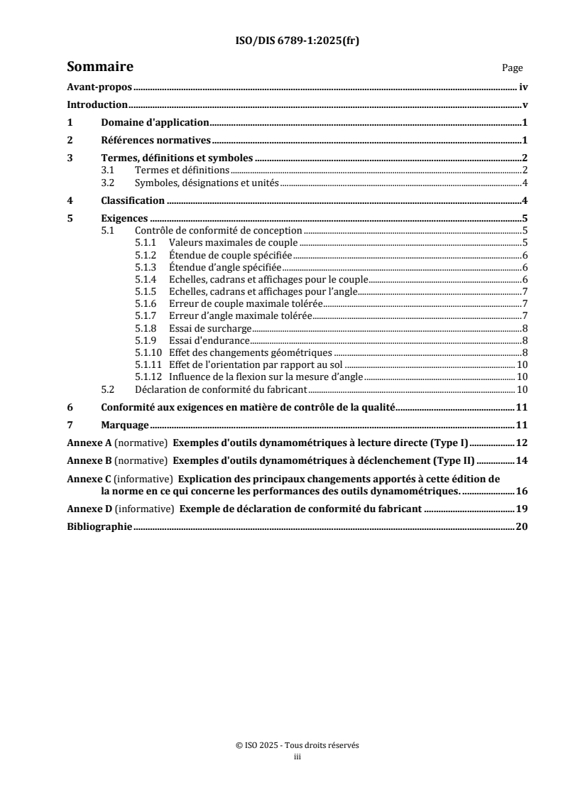
Sommaire Page
Avant-propos . iv
Introduction . v
1 Domaine d'application . 1
2 Références normatives . 1
3 Termes, définitions et symboles . 2
3.1 Termes et définitions . 2
3.2 Symboles, désignations et unités . 4
4 Classification . 4
5 Exigences . 5
5.1 Contrôle de conformité de conception . 5
5.1.1 Valeurs maximales de couple . 5
5.1.2 Étendue de couple spécifiée . 6
5.1.3 Étendue d’angle spécifiée . 6
5.1.4 Echelles, cadrans et affichages pour le couple . 6
5.1.5 Echelles, cadrans et affichages pour l’angle . 7
5.1.6 Erreur de couple maximale tolérée . 7
5.1.7 Erreur d’angle maximale tolérée . 7
5.1.8 Essai de surcharge . 8
5.1.9 Essai d'endurance . 8
5.1.10 Effet des changements géométriques . 8
5.1.11 Effet de l'orientation par rapport au sol . 10
5.1.12 Influence de la flexion sur la mesure d’angle . 10
5.2 Déclaration de conformité du fabricant . 10
6 Conformité aux exigences en matière de contrôle de la qualité . 11
7 Marquage . 11
Annexe A (normative) Exemples d'outils dynamométriques à lecture directe (Type I) . 12
Annexe B (normative) Exemples d'outils dynamométriques à déclenchement (Type II) . 14
Annexe C (informative) Explication des principaux changements apportés à cette édition de
la norme en ce qui concerne les performances des outils dynamométriques. . 16
Annexe D (informative) Exemple de déclaration de conformité du fabricant . 19
Bibliographie . 20
iii
ISO/DIS 6789-1:2025(fr)
Avant-propos
L'ISO (Organisation internationale de normalisation) est une fédération mondiale d'organismes
nationaux de normalisation (comités membres de l'ISO). L'élaboration des Normes internationales est en
général confiée aux comités techniques de l'ISO. Chaque comité membre intéressé par une étude a le droit
de faire partie du comité technique créé à cet effet. Les organisations internationales, gouvernementales
et non gouvernementales, en liaison avec l'ISO participent également aux travaux. L'ISO collabore
étroitement avec la Commission électrotechnique internationale (IEC) en ce qui concerne la
normalisation électrotechnique.
Les procédures utilisées pour élaborer le présent document et celles destinées à sa mise à jour sont
décrites dans les Directives ISO/IEC, Partie 1. Il convient, en particulier, de prendre note des différents
critères d'approbation requis pour les différents types de documents ISO. Le présent document a été
rédigé conformément aux règles de rédaction données dans les Directives ISO/IEC, Partie 2 (voir
www.iso.org/directives).
L'ISO attire l'attention sur le fait que la mise en application du présent document peut entraîner
l'utilisation d'un ou de plusieurs brevets. L'ISO ne saurait être tenue pour responsable de ne pas avoir
identifié tout ou partie de tels droits de propriété. Les détails concernant les références aux droits de
propriété intellectuelle ou autres droits analogues identifiés lors de l'élaboration du document sont
indiqués dans l'Introduction et/ou dans la liste des déclarations de brevets reçues par l'ISO (voir
www.iso.org/brevets).
Les appellations commerciales éventuellement mentionnées dans le présent document sont données
pour information, par souci de commodité, à l'intention des utilisateurs, et ne sauraient constituer un
engagement.
Pour une explication de la nature volontaire des normes, la signification des termes et expressions
spécifiques de l'ISO liés à l'évaluation de la conformité, ou pour toute information au sujet de l'adhésion
de l'ISO aux principes de l’Organisation mondiale du commerce (OMC) concernant les obstacles
techniques au commerce (OTC), voir www.iso.org/avant-propos.
Le présent document a été élaboré par le Comité technique ISO/TC 29, Petit outillage, sous-comité SC 10,
Outils de manœuvre pour vis et écrous, pinces et tenailles.
Cette deuxième édition de l’ISO 6789-1, avec la révision de l’ISO 6789-2 et l’ajout de l’ISO 6789-3, annule
et remplace l’ISO 6789-1:2017 et l’ISO 6789-2:2017 qui a fait l’objet d’une révision technique avec les
modifications suivantes. L’ISO 6789-1:2017 a été divisée en deux parties. Les exigences relatives à la
conception et au contrôle de la qualité pendant la fabrication, ainsi que la déclaration de conformité du
fabricant, s’adressent désormais uniquement aux fabricants et figurent toujours dans l’ISO 6789-1. Les
exigences minimales pour la vérification de la conformité des outils pendant leur utilisation sont
transférées dans la nouvelle ISO 6789-3.
Les exigences minimales en matière d’étalonnage figurent toujours dans l’ISO 6789-2
iv
ISO/DIS 6789-1:2025(fr)
Introduction
Cette révision a intégré les retours d'expérience des utilisateurs sur les sujets généraux suivants.
Clarifier pour les utilisateurs de la norme les parties qu’il convient d’acheter pour effectuer leur
travail relatif aux outils dynamométriques à commande manuelle. (Voir ci-dessous)
Réduire de manière significative le nombre d’incertitudes de mesure exigées pour fournir un
certificat d'étalonnage
Séparer la déclaration de conformité émise par un fabricant du rapport de performance émis par
un laboratoire d'essai ou une fonction interne de contrôle de la qualité.
L'étalonnage ou la vérification des mesures d'angle que l'on trouve dans un nombre croissant
d'outils dynamométriques
L'ajout d'outils qui peuvent être à lecture directe ou à déclenchement en fonction des besoins du
client.
Les trois parties de l'ISO 6789 qui résultent de cette révision peuvent être résumées comme suit :
L’ISO 6789-1 maintien des exigences minimales pour le développement et la documentation
d'outils dynamométriques à commande manuelle à l'attention des concepteurs et des fabricants.
Le fabricant peut choisir le niveau de documentation fourni avec l'outil en fonction des besoins
typiques de ses clients. Il peut s’agir d’un certificat d’étalonnage conforme à l’ISO 6789-2 ou d’un
rapport de vérification conforme à l’ISO 6789-3
L’ISO 6789-2 fournit aux fabricants et aux laboratoires d’étalonnage des exigences pour
l‘étalonnage du couple et de l’angle des outils dynamométriques à commande manuelle, ainsi que
des méthodes simplifiées pour le calcul des incertitudes. En outre, les exigences minimales pour
l’étalonnage des dispositifs de mesure du couple, en tant qu’alternative lorsque les normes
nationales ne sont pas disponibles, sont décrites dans l’ISO 6789-2, Annexe C
L'ISO 6789-3 fournit les exigences de base pour vérifier et indiquer si l'outil dynamométrique est
conforme aux exigences de performance de couple de l'ISO 6789-1. Elle a été créée en tant que
norme distincte afin de la rendre plus accessible aux utilisateurs qui ne sont pas des fabricants
d'outils dynamométriques. La vérification définie dans la norme ISO 6789-3 ne contient pas autant
d’informations détaillées et n’offre donc pas le même degré de confiance dans les performances
de l’outil dynamométrique qu’un certificat d’étalonnage défini dans l’ISO 6789-2.
Les scénarios suivants peuvent aider les utilisateurs de la série ISO 6789 à identifier la ou les partie(s)
appropriée(s) applicable(s) à leurs activités :
Le client exige un outil dynamométrique avec un certificat d'étalonnage accrédité afin de répondre aux
exigences législatives ou commerciales. La solution consiste à acheter un outil dynamométrique et à le
soumettre à un laboratoire d'étalonnage accrédité pour obtenir un certificat d'étalonnage. (Note :
Certains fabricants d’outils dynamométriques peuvent proposer un tel service.) Il convient que
l’étalonnage soit conforme à l’ISO 6789-2. L’outil dynamométrique sera fourni avec une déclaration de
conformité du fabricant attestant que l’outil est conforme aux exigences de conception de l’ISO 6789-1
Le client a besoin d'un certificat d'étalonnage pour comprendre les performances techniques de l'outil
dynamométrique. La solution consiste à acheter un outil dynamométrique qui est fourni avec un certificat
d'étalonnage. Si un tel produit n’est pas disponible, un outil dynamométrique accompagné d’un rapport
de vérification des performances conforme à l’ISO 6789-3 peut être acheté et soumis à un laboratoire
d’étalonnage pour être étalonné conformément à l’ISO 6789-2. L’outil dynamométrique sera fourni avec
une déclaration de conformité du fabricant attestant que l’outil est conforme aux exigences de conception
de l’ISO 6789-1
Le client n’a pas de contraintes législatives, commerciales ou techniques, mais il aimerait quand même
avoir la confirmation que l’outil dynamométrique fonctionnera avec le niveau d’exactitude exigé. La
v
ISO/DIS 6789-1:2025(fr)
solution consiste à acheter un outil dynamométrique qui possède une déclaration de conformité du
fabricant confirmant que l’outil a été conçu et soumis à essai au cours de son développement
conformément à l’ISO 6789-1 et qui est accompagné d’un rapport de vérification des performances
indiquant le niveau d’exactitude de l'outil en question. Il convient que l’absence des contraintes
susmentionnées ne dissuade pas le client d'obtenir les informations et la protection juridique accrue
qu'offre un certificat d'étalonnage par rapport à un rapport de vérification des performances.
vi
PROJET de norme internationale ISO/DIS 6789-1:2025(fr)
Outils de manœuvre pour vis et écrous — Outils dynamométriques
à commande manuelle — Partie 1 : Exigences et méthodes d’essai
pour vérifier la conformité de conception et la conformité de
qualité : exigences minimales pour déclaration de conformité
1 Domaine d'application
Le présent document spécifie les exigences d'essai de conformité et de marquage relatives aux outils
dynamométriques à commande manuelle utilisés pour le serrage contrôlé de vis et écrous. Elle spécifie
également les exigences minimales relatives à la déclaration de conformité d’un fabricant d’outils
dynamométriques à commande manuelle.
Le présent document s’applique aux outils dynamométriques à commande manuelle classés en tant
qu’outils dynamométriques à lecture directe (Type I) et outils dynamométriques à déclenchement
(Type II).
NOTE Les outils dynamométriques à commande manuelle couverts par le présent document sont ceux identifiés
dans l’ISO 1703:2018 par les numéros de référence 7 1 00 01 0 à 7 1 00 14 0 inclus. Les outils dynamométriques à
commande manuelle à limiteur de couple n’ont pas encore de numéros de référence et n’en auront pas avant la
prochaine révision de l’ISO 1703.
Le présent document ne spécifie pas d'exigences relatives aux certificats d'étalonnage des outils
dynamométriques à commande manuelle. Celles-ci sont décrites dans l’ISO 6789-2.
Le présent document ne spécifie pas d’exigences relatives à la vérification des performances des outils
dynamométriques à commande manuelle. Celles-ci sont décrites dans l’ISO 6789-3.
2 Références normatives
Les documents suivants sont cités dans le texte de sorte qu’ils constituent, pour tout ou partie de leur
contenu, des exigences du présent document. Pour les références datées, seule l’édition citée s’applique.
Pour les références non datées, la dernière édition du document de référence s'applique (y compris les
éventuels amendements).
ISO 1173, Outils de manœuvre pour vis et écrous — Entraînements des embouts tournevis à main et à
machine et éléments de connexion — Dimensions, couple d'essai
ISO 1174-1, Outils de manœuvre pour vis et écrous — Carrés d'entraînement — Partie 1 : Carrés
d'entraînement pour outils à main
ISO 6789-2:2025, Outils de manœuvre pour vis et écrous — Outils dynamométriques à commande manuelle
— Partie 2 : Exigences d'étalonnage et détermination de l'incertitude de mesure
ISO 6789-3:2025, Outils de manœuvre pour vis et écrous — Outils dynamométriques à commande manuelle
— Exigences et méthodes d'essai pour vérifier la conformité de conception, la conformité de qualité et la
procédure de réétalonnage — Partie 3: Exigences et méthodes pour les essais intermédiaires
ISO/IEC 17025, Exigences générales concernant la compétence des laboratoires d'étalonnages et d'essais
ISO/DIS 6789-1:2025(fr)
3 Termes, définitions et symboles
3.1 Termes et définitions
Pour les besoins du présent document, les termes et définitions suivants s'appliquent.
L’ISO et l’IEC tiennent à jour des bases de données terminologiques destinées à être utilisées en
normalisation, consultables aux adresses suivantes :
— IEC Electropedia : disponible à l’adresse https://www.electropedia.org/
— ISO Online browsing platform : disponible à l’adresse https://www.iso.org/obp
3.1.1
contrôle de conformité de conception
examen technique de conformité aux exigences à respecter pendant la conception ou la modification des
outils dynamométriques à commande manuelle
3.1.2
contrôle de conformité de qualité
examen technique de conformité aux exigences à respecter pendant la fabrication de l’outil
dynamométrique à commande manuelle
3.1.3
déclaration de conformité du fabricant
information documentée fournie par le fabricant stipulant que l'outil dynamométrique est conforme aux
exigences du présent document
3.1.4
erreur relative maximale tolérée
valeur maximale de l'erreur de mesure observée de l'outil dynamométrique exprimée en pourcentage de
la valeur du couple de référence sur le dispositif de mesure du couple
Note 1 à l'article : Le terme « exactitude » est encore parfois utilisé en lieu et place du terme « erreur maximale
tolérée », ce qui est cependant techniquement incorrect. L’« exactitude de mesure » n'est pas une grandeur et ne
s'exprime pas numériquement. Un mesurage est quelquefois dit plus exact s'il fournit une plus petite erreur de
mesure.
Note 2 à l'article : L’erreur est définie comme la différence entre la valeur mesurée d’une grandeur et une valeur de
référence dans le Guide ISO/IEC 99.
3.1.5
système de mesure de couple
combinaison d'un dispositif de mesure de couple et d'un système de chargement permettant d'appliquer
un couple, qui sert d'étalon de mesure pour l'outil dynamométrique à commande manuelle
Note 1 à l’article : Un système d'étalonnage tel que défini dans l'ISO 6789-2 peut également être utilisé comme
système de mesure de couple dans le présent document.
3.1.6
dispositif de mesure de couple
étalon de mesure de travail fourni soit mécaniquement soit par un transducteur de couple électronique
associé à un système d'affichage
ISO/DIS 6789-1:2025(fr)
3.1.7
mesure directe d'angle
mesure d'angle où l'angle de rotation est directement mesuré en mesurant la proportion d'un tour
complet de l'élément rotatif
Note 1 à l’article : Ce type de dispositif de mesure utilise généralement un rapporteur ou un système de codage
angulaire
3.1.8
mesure indirecte d'angle
mesure d'angle où l'angle de rotation est indirectement mesuré ou défini par un mesurande déterminé
mathématiquement et proportionnel à l'angle de rotation.
Note 1 à l’article : Ce type de dispositif de mesure utilise généralement un gyroscope ou un dispositif similaire sur
un bras de levier
3.1.9
système de mesure d’angle
combinaison d’un dispositif de mesure d’angle et d’un système de chargement permettant d’appliquer un
effort tangentiel, qui sert d’étalon de mesure d’angle pour l’outil dynamométrique à commande manuelle
Note 1 à l’article : Un système d’étalonnage tel que défini dans l’ISO 6789-2 peut également être utilisé comme
système de mesure d’angle dans le présent document.
3.1.10
dispositif de mesure d’angle
étalon de mesure de travail fourni soit mécaniquement soit par un transducteur de couple électronique
associé à un codeur électronique angulaire et système d'affichage
3.1.11
outil dynamométrique à lecture directe (Type I)
outil qui indique, au moyen d’une échelle mécanique, d’un cadran ou d’un lecteur électronique, la valeur
du couple exercé par l’outil sur l’entraînement de sortie
3.1.12
outil dynamométrique à déclenchement (Type II)
outil qui détecte le couple transmis en comparant le couple appliqué à un étalon autonome et qui signale
la transmission de la valeur préréglée par une impulsion physique, avec ou sans signal sonore, entraînant
une réduction temporaire du couple appliqué
Note 1 à l’article : Certains outils dynamométriques à déclenchement peuvent également être utilisés comme outil
à lecture directe sans signaler la transmission de la valeur présélectionnée. Dans ce mode, ils agissent comme des
outils dynamométriques à lecture directe. Il convient que les fabricants indiquent clairement aux utilisateurs les
performances de l'outil dynamométrique dans chaque mode.
3.1.13
clé réglable à échelle graduée ou avec affichage numérique
outil conçu pour être ajusté par l'utilisateur, qui possède une échelle ou un affichage numérique pour
permettre l'ajustement
3.1.14
clé réglable non graduée
outil conçu pour être ajusté par l'utilisateur à l'aide d'un système de mesure de couple
ISO/DIS 6789-1:2025(fr)
3.1.15
clé à couple fixe
outil non conçu pour être ajusté par l'utilisateur, c'est-à-dire ayant un réglage unique
3.1.16
clé à limiteur de couple
outil conçu pour empêcher le transfert d’un couple supérieur à la valeur réglée
Note 1 à l’article : Pour ce faire, on insère souvent un ressort dans le mécanisme de transfert de couple, de sorte
qu’au-delà d’une certaine valeur, le ressort se comprime ou s’allonge toujours et empêche tout nouveau transfert
de couple.
3.2 Symboles, désignations et unités
Les désignations utilisées dans le présent document sont répertoriées dans le Tableau 1.
Tableau 1 — Symboles, désignations et unités
Symbole Désignation Unité
a Erreur relative de la sortie de l'outil dynamométrique par rapport au couple cible %
Valeur de couple souhaitée, qui peut être la valeur indiquée, réglée, nominale, selon le
Xa N ⋅ m
type et la classe de l'outil dynamométrique
Xo Valeur observée, indiquée par le dispositif de mesure de couple N ⋅ m
aθ Erreur absolue de l'angle mesuré par l'outil par rapport à l'angle cible °
θ Valeur de l'angle indiqué par l'outil dynamométrique °
a
θ Valeur observée, indiquée par le dispositif de mesure d’angle °
o
4 Classification
Les outils dynamométriques à commande manuelle objet du présent document sont classifiés comme
suit.
a) Outils dynamométriques à lecture directe (Type I ; voir Annexe A) :
1) Classe A : Clé à barre de torsion ou de flexion ;
2) Classe B : Clé à boîtier rigide avec secteur gradué ou cadran ou affichage numérique ;
3) Classe C : Clé à boîtier rigide et mesure électronique ;
4) Classe D : Tournevis avec secteur gradué ou cadran ou affichage numérique ;
5) Classe E : Tournevis avec mesure électronique ;
b) Outils dynamométriques à déclenchement (Type II ; voir Annexe B) :
1) Classe A : Clé réglable à échelle graduée ou avec affichage numérique ;
2) Classe B : Clé à couple fixe ;
3) Classe C : Clé réglable non graduée ;
4) Classe D : Tournevis réglable à échelle graduée ou avec affichage numérique ;
ISO/DIS 6789-1:2025(fr)
5) Classe E : Tournevis à couple fixe ;
6) Classe F : Tournevis réglable non gradué ;
7) Classe G : Clé à barre de flexion, réglable à échelle graduée
8) Classe H : Clé à limiteur de couple réglable à échelle graduée
9) Classe J : Clé à limiteur de couple à couple fixe
10) Classe K : Clé à limiteur de couple réglable non graduée
5 Exigences
5.1 Contrôle de conformité de conception
Au cours des différentes étapes de la conception et lors de toute modification ultérieure de la conception
des outils dynamométriques couverts par la présente norme, le fabricant doit vérifier la conformité à
chacun des Articles du 5.1 qui s'applique à ce type d'outil et doit documenter les résultats des essais.
Les détails des essais de conformité doivent être déterminés par le fabricant conformément à son système
de gestion de la qualité.
Lorsque les exigences suivantes incluent la mesure du couple ou de l’angle, la conformité doit être établie
en effectuant des étalonnages conformément à l’ISO 6789-2.
5.1.1 Valeurs maximales de couple
La dimension de l'entraînement de sortie limite la valeur maximale du couple de l'outil dynamométrique
concerné. L'affectation est faite en fonction des valeurs données dans le Tableau 2. Pour les sorties non
spécifiées au Tableau 2, la dimension de l’entraînement de sortie est déterminée par le couple maximal
de l’outil dynamométrique correspondant et doit être conforme aux exigences du 5.1.8 et du 5.1.9.
Tableau 2 — Valeurs maximales de couple de l'outil dynamométrique
Carré Entraînement de
Valeur maximale de
Entraînement de sortie hexagonal
couple
sortie carré
a b
dimension nominale dimension nominale
N⋅m
en mm en mm
— 3 4
— 4 10
— 5,5 25
6,3 6,3 30
— 8 70
10 — 135
— 11,2 200
12,5 12,5 340
20 — 1 000
25 — 2 100
a
Dimensions conformément à l'ISO 1174-1.
b
Dimensions conformément à l'ISO 1173.
ISO/DIS 6789-1:2025(fr)
5.1.2 Étendue de couple spécifiée
Les exigences et les méthodes décrites dans le présent document couvrent une étendue de couples
spécifiés qui est fonction du type et de la classe de l'outil dynamométrique.
L'étendue ou la
...
Questions, Comments and Discussion
Ask us and Technical Secretary will try to provide an answer. You can facilitate discussion about the standard in here.
Loading comments...