

ISO/PRF 21815-5
(Main)Earth-moving machinery — Collision warning and avoidance — Part 5: Risk area and risk level for other forms of motion
General Information
- Abstract
This document defines requirements for collision warning (CWS) and collision avoidance systems (CAS) that address other forms of motion than forward/reverse and rotation for: — earth-moving machinery as defined in ISO 6165, — mobile underground mining machinery as defined in ISO 19296, rock drill rigs as defined in ISO 22935-5, and — road construction machinery as defined in ISO 22242. Clauses 5, 6, 7, and 8 do not consider machine height beyond that of height in travel position as established by machine manufacturer. The requirements for forward / reverse motion are stated in ISO 21815-3:2023 and for swing/rotation motion in ISO 21815-4:20XX. This document covers — collision warning and avoidance for articulation movement by speed reduction, stopping, or motion inhibit, Note: Steering the machine whilst in forward/reverse motion is not considered as articulation motion. — collision warning and avoidance for 4-wheel steer motion by speed reduction, stopping, or motion inhibit, — collision warning and avoidance for motion of towed trailers in reverse by speed reduction, stopping, or motion inhibit, — collision warning and avoidance for differential speed, skid turning, counter rotation motion by speed reduction, stopping, or motion inhibit, — collision warning and avoidance for telescopic extension/ retraction motions, and — collision warning and avoidance for vertical motions i.e. height or depth For articulation this document considers • a stationary machine when an articulation command is given • during articulation, where no linear motion takes place (i.e. forward / reverse). This document does not cover avoidance by automatic manoeuvring (e.g. steering) away from the object. The system described in this standard is intended to assist the operator of the machine. The responsibility for safe operation of the machine remains with the machine operator. This document is not applicable to collision warning and collision avoidance systems installed or manufactured before the date of its publication. Machines that are double articulated are excluded from the scope of this document.
- Status
- Not Published
- Technical Committee
- ISO/TC 127/SC 2 - Safety, ergonomics and general requirements
- Current Stage
- 5020 - FDIS ballot initiated: 2 months. Proof sent to secretariat
- Start Date
- 09-Sep-2026
- Completion Date
- 12-Sep-2026
Buy Documents
ISO/PRF 21815-5 - Earth-moving machinery — Collision warning and avoidance — Part 5: Risk area and risk level for other forms of motion

REDLINE ISO/PRF 21815-5 - Earth-moving machinery — Collision warning and avoidance — Part 5: Risk area and risk level for other forms of motion
Overview
ISO/PRF 21815-5: Earth-moving machinery - Collision warning and avoidance - Part 5: Risk area and risk level for other forms of motion specifies critical requirements for collision warning systems (CWS) and collision avoidance systems (CAS) targeting motions beyond traditional forward/reverse and swing/rotation operations. Developed by ISO, this international standard addresses key safety challenges associated with complex machinery movements such as articulation, four-wheel steering, motion of towed trailers in reverse, differential speed/skid turning, telescopic motion, and vertical (height/depth) movements.
Target machines include:
- Earth-moving machinery (see ISO 6165)
- Mobile underground mining machinery (see ISO 19296)
- Rock drill rigs (ISO 22932-5)
- Road construction machinery (ISO 22242)
This standard is intended to assist operators by highlighting risk areas and specifying required system responses. The operator remains ultimately responsible for safety.
Key Topics
Scope of Motion
ISO/PRF 21815-5 covers the following types of machine motion relevant to CWS and CAS:
- Articulation motion: Addressed for stationary and moving objects when a machine pivots at an articulation point
- Four-wheel steering: Enhances maneuverability but introduces collision risks in unexpected areas
- Towed trailers in reverse: Focuses on collision risks during backward movements of attached trailers
- Differential speed/skid turning/counter rotation: Includes complex movements where opposing wheels move at varying speeds or directions
- Telescopic extension/retraction: Applies to machines with extendible components affecting the risk envelope
- Vertical movement: Includes lifting or lowering parts, impacting object collision zones above and below the machine
Collision Risk Levels (CRLs)
The standard introduces a graduated risk level approach:
- CRL 1: Object present but no collision risk
- CRL 2: Collision possible if movement continues, but no action required
- CRL 3–5: Escalating levels of collision risk leading from operator warning (CWS) up to intervention (CAS), such as slowing, stopping, or motion inhibition
CRL assignment relies on continuous assessment of object position, speed, and direction relative to machine motion.
System Requirements and Operator Support
- Detection zones must be appropriately defined for each machine configuration and attachment
- Systems must communicate risk levels and actions clearly to operators
- The limits of detection and system capabilities must be outlined in manuals and operator instructions
Applications
ISO/PRF 21815-5 provides practical benefits for improving machinery safety, operational continuity, and risk management across industries utilizing heavy machinery:
- Construction sites: Excavators, loaders, and other earth-moving machines with articulated frames or telescoping booms
- Mining operations: Underground and surface mining vehicles requiring articulated steering and complex movement detection
- Road building: Pavers and graders with four-wheel steering or trailers
- Manufacturers and system integrators: Those designing CWS and CAS for compliant machine architectures
- Maintenance and safety auditing: For specifying and verifying compliant safety systems during use or retrofitting
By defining risk area calculations and actions for non-linear machine movement, the standard supports reduction of collision incidents and helps maintain regulatory compliance and site safety best practices.
Related Standards
ISO/PRF 21815-5 is part of a broader suite of international standards for earth-moving machinery safety:
- ISO 21815-3:2023: Collision warning and avoidance for forward/reverse motion
- ISO 21815-4 (in preparation): Collision warning and avoidance for swing/rotation
- ISO 6165: Terminology and definitions for earth-moving machinery
- ISO 19296: Safety for mobile underground mining machines
- ISO 22932-5: Rock drill rigs
- ISO 22242: Road construction machinery
- ISO 12100: General principles for risk assessment and risk reduction
Adhering to ISO/PRF 21815-5 ensures up-to-date compliance for advanced motion detection and collision mitigation, complementing other key international safety standards for construction, mining, and road machinery operations.
Buy Documents
ISO/PRF 21815-5 - Earth-moving machinery — Collision warning and avoidance — Part 5: Risk area and risk level for other forms of motion
REDLINE ISO/PRF 21815-5 - Earth-moving machinery — Collision warning and avoidance — Part 5: Risk area and risk level for other forms of motion
Frequently Asked Questions
ISO/PRF 21815-5 is a draft published by the International Organization for Standardization (ISO). Its full title is "Earth-moving machinery — Collision warning and avoidance — Part 5: Risk area and risk level for other forms of motion". This standard covers: This document defines requirements for collision warning (CWS) and collision avoidance systems (CAS) that address other forms of motion than forward/reverse and rotation for: — earth-moving machinery as defined in ISO 6165, — mobile underground mining machinery as defined in ISO 19296, rock drill rigs as defined in ISO 22935-5, and — road construction machinery as defined in ISO 22242. Clauses 5, 6, 7, and 8 do not consider machine height beyond that of height in travel position as established by machine manufacturer. The requirements for forward / reverse motion are stated in ISO 21815-3:2023 and for swing/rotation motion in ISO 21815-4:20XX. This document covers — collision warning and avoidance for articulation movement by speed reduction, stopping, or motion inhibit, Note: Steering the machine whilst in forward/reverse motion is not considered as articulation motion. — collision warning and avoidance for 4-wheel steer motion by speed reduction, stopping, or motion inhibit, — collision warning and avoidance for motion of towed trailers in reverse by speed reduction, stopping, or motion inhibit, — collision warning and avoidance for differential speed, skid turning, counter rotation motion by speed reduction, stopping, or motion inhibit, — collision warning and avoidance for telescopic extension/ retraction motions, and — collision warning and avoidance for vertical motions i.e. height or depth For articulation this document considers • a stationary machine when an articulation command is given • during articulation, where no linear motion takes place (i.e. forward / reverse). This document does not cover avoidance by automatic manoeuvring (e.g. steering) away from the object. The system described in this standard is intended to assist the operator of the machine. The responsibility for safe operation of the machine remains with the machine operator. This document is not applicable to collision warning and collision avoidance systems installed or manufactured before the date of its publication. Machines that are double articulated are excluded from the scope of this document.
This document defines requirements for collision warning (CWS) and collision avoidance systems (CAS) that address other forms of motion than forward/reverse and rotation for: — earth-moving machinery as defined in ISO 6165, — mobile underground mining machinery as defined in ISO 19296, rock drill rigs as defined in ISO 22935-5, and — road construction machinery as defined in ISO 22242. Clauses 5, 6, 7, and 8 do not consider machine height beyond that of height in travel position as established by machine manufacturer. The requirements for forward / reverse motion are stated in ISO 21815-3:2023 and for swing/rotation motion in ISO 21815-4:20XX. This document covers — collision warning and avoidance for articulation movement by speed reduction, stopping, or motion inhibit, Note: Steering the machine whilst in forward/reverse motion is not considered as articulation motion. — collision warning and avoidance for 4-wheel steer motion by speed reduction, stopping, or motion inhibit, — collision warning and avoidance for motion of towed trailers in reverse by speed reduction, stopping, or motion inhibit, — collision warning and avoidance for differential speed, skid turning, counter rotation motion by speed reduction, stopping, or motion inhibit, — collision warning and avoidance for telescopic extension/ retraction motions, and — collision warning and avoidance for vertical motions i.e. height or depth For articulation this document considers • a stationary machine when an articulation command is given • during articulation, where no linear motion takes place (i.e. forward / reverse). This document does not cover avoidance by automatic manoeuvring (e.g. steering) away from the object. The system described in this standard is intended to assist the operator of the machine. The responsibility for safe operation of the machine remains with the machine operator. This document is not applicable to collision warning and collision avoidance systems installed or manufactured before the date of its publication. Machines that are double articulated are excluded from the scope of this document.
ISO/PRF 21815-5 is classified under the following ICS (International Classification for Standards) categories: 53.100 - Earth-moving machinery. The ICS classification helps identify the subject area and facilitates finding related standards.
ISO/PRF 21815-5 is available in PDF format for immediate download after purchase. The document can be added to your cart and obtained through the secure checkout process. Digital delivery ensures instant access to the complete standard document.
Standards Content (Sample)
International
Standard
ISO 21815-5
First edition
Earth-moving machinery —
2026-11
Collision warning and avoidance —
Part 5:
Risk area and risk level for other
forms of motion
Engins de terrassement - Avertissement et évitement de
collision —
Partie 5: Zone de risque et niveau de risque pour les autres formes
de mouvement
PROOF/ÉPREUVE
Reference number
ISO 21815-5:2026(en) © ISO 2026
ISO 21815-5:2026(en)
© ISO 2026
All rights reserved. Unless otherwise specified, or required in the context of its implementation, no part of this publication may
be reproduced or utilized otherwise in any form or by any means, electronic or mechanical, including photocopying, or posting on
the internet or an intranet, without prior written permission. Permission can be requested from either ISO at the address below
or ISO’s member body in the country of the requester.
ISO copyright office
CP 401 • Ch. de Blandonnet 8
CH-1214 Vernier, Geneva
Phone: +41 22 749 01 11
Email: copyright@iso.org
Website: www.iso.org
Published in Switzerland
PROOF/ÉPREUVE
ii
ISO 21815-5:2026(en)
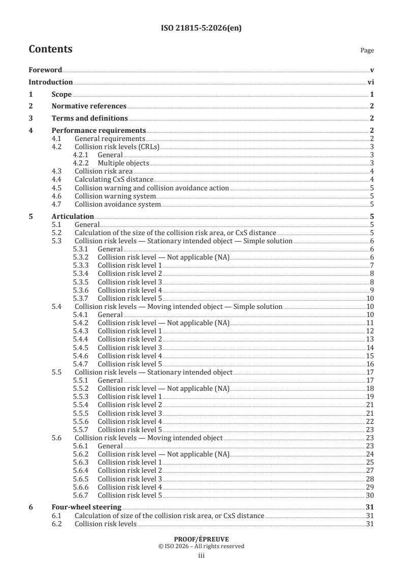
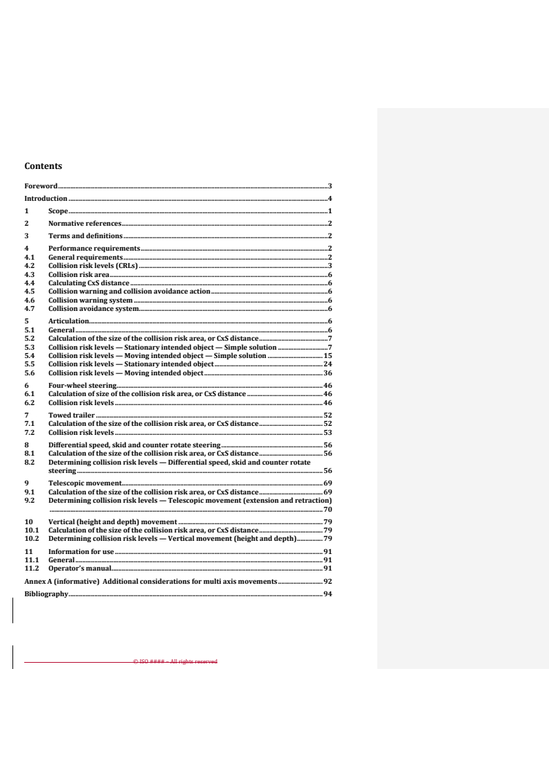
Contents Page
Foreword .v
Introduction .vi
1 Scope . 1
2 Normative references . 2
3 Terms and definitions . 2
4 Performance requirements . . 2
4.1 General requirements .2
4.2 Collision risk levels (CRLs) .3
4.2.1 General .3
4.2.2 Multiple objects .3
4.3 Collision risk area .4
4.4 Calculating CxS distance .4
4.5 Collision warning and collision avoidance action .5
4.6 Collision warning system .5
4.7 Collision avoidance system .5
5 Articulation . 5
5.1 General .5
5.2 Calculation of the size of the collision risk area, or CxS distance .5
5.3 Collision risk levels — Stationary intended object — Simple solution .6
5.3.1 General .6
5.3.2 Collision risk level — Not applicable (NA) .6
5.3.3 Collision risk level 1 .7
5.3.4 Collision risk level 2 .8
5.3.5 Collision risk level 3 .8
5.3.6 Collision risk level 4 .9
5.3.7 Collision risk level 5 .10
5.4 Collision risk levels — Moving intended object — Simple solution .10
5.4.1 General .10
5.4.2 Collision risk level — Not applicable (NA) .11
5.4.3 Collision risk level 1 . 12
5.4.4 Collision risk level 2 . 13
5.4.5 Collision risk level 3 .14
5.4.6 Collision risk level 4 . 15
5.4.7 Collision risk level 5 .16
5.5 Collision risk levels — Stationary intended object .17
5.5.1 General .17
5.5.2 Collision risk level — Not applicable (NA) .18
5.5.3 Collision risk level 1 .19
5.5.4 Collision risk level 2 .21
5.5.5 Collision risk level 3 .21
5.5.6 Collision risk level 4 . 22
5.5.7 Collision risk level 5 . 23
5.6 Collision risk levels — Moving intended object . 23
5.6.1 General . 23
5.6.2 Collision risk level — Not applicable (NA) .24
5.6.3 Collision risk level 1 . 25
5.6.4 Collision risk level 2 .27
5.6.5 Collision risk level 3 . 28
5.6.6 Collision risk level 4 . 29
5.6.7 Collision risk level 5 . 30
6 Four-wheel steering .31
6.1 Calculation of size of the collision risk area, or CxS distance .31
6.2 Collision risk levels .31
PROOF/ÉPREUVE
iii
ISO 21815-5:2026(en)
6.2.1 General .31
6.2.2 Four-wheel steering — Circle steer .31
6.2.3 Four-wheel steering — Crab steering .32
6.2.4 Crab steering — Motor graders . 33
6.2.5 Collision risk levels . 33
7 Towed trailer .35
7.1 Calculation of the size of the collision risk area, or CxS distance . 35
7.2 Collision risk levels . 35
7.2.1 General . 35
7.2.2 Collision risk levels — Fixed axle trailers . . 36
7.2.3 Collision risk levels — Following axle trailers . 36
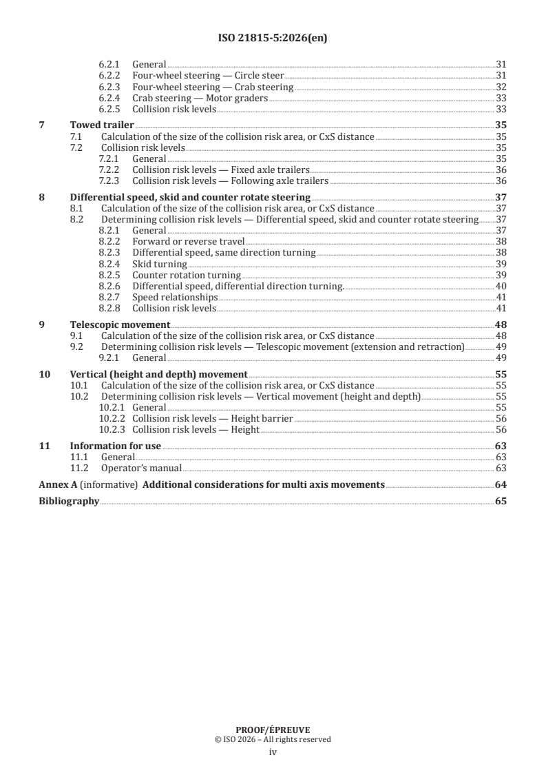
8 Differential speed, skid and counter rotate steering .37
8.1 Calculation of the size of the collision risk area, or CxS distance .37
8.2 Determining collision risk levels — Differential speed, skid and counter rotate steering .37
8.2.1 General .37
8.2.2 Forward or reverse travel . 38
8.2.3 Differential speed, same direction turning . 38
8.2.4 Skid turning . 39
8.2.5 Counter rotation turning . 39
8.2.6 Differential speed, differential direction turning. . 40
8.2.7 Speed relationships .41
8.2.8 Collision risk levels .41
9 Telescopic movement .48
9.1 Calculation of the size of the collision risk area, or CxS distance . 48
9.2 Determining collision risk levels — Telescopic movement (extension and retraction) . 49
9.2.1 General . 49
10 Vertical (height and depth) movement .55
10.1 Calculation of the size of the collision risk area, or CxS distance . 55
10.2 Determining collision risk levels — Vertical movement (height and depth) . 55
10.2.1 General . 55
10.2.2 Collision risk levels — Height barrier . 56
10.2.3 Collision risk levels — Height . 56
11 Information for use .63
11.1 General . 63
11.2 Operator’s manual . 63
Annex A (informative) Additional considerations for multi axis movements .64
Bibliography .65
PROOF/ÉPREUVE
iv
ISO 21815-5:2026(en)
Foreword
ISO (the International Organization for Standardization) is a worldwide federation of national standards
bodies (ISO member bodies). The work of preparing International Standards is normally carried out through
ISO technical committees. Each member body interested in a subject for which a technical committee
has been established has the right to be represented on that committee. International organizations,
governmental and non-governmental, in liaison with ISO, also take part in the work. ISO collaborates closely
with the International Electrotechnical Commission (IEC) on all matters of electrotechnical standardization.
The procedures used to develop this document and those intended for its further maintenance are described
in the ISO/IEC Directives, Part 1. In particular, the different approval criteria needed for the different types
of ISO document should be noted. This document was drafted in accordance with the editorial rules of the
ISO/IEC Directives, Part 2 (see www.iso.org/directives).
ISO draws attention to the possibility that the implementation of this document may involve the use of (a)
patent(s). ISO takes no position concerning the evidence, validity or applicability of any claimed patent
rights in respect thereof. As of the date of publication of this document, ISO had not received notice of (a)
patent(s) which may be required to implement this document. However, implementers are cautioned that
this may not represent the latest information, which may be obtained from the patent database available at
www.iso.org/patents. ISO shall not be held responsible for identifying any or all such patent rights.
Any trade name used in this document is information given for the convenience of users and does not
constitute an endorsement.
For an explanation of the voluntary nature of standards, the meaning of ISO specific terms and expressions
related to conformity assessment, as well as information about ISO's adherence to the World Trade
Organization (WTO) principles in the Technical Barriers to Trade (TBT), see www.iso.org/iso/foreword.html.
This document was prepared by Technical Committee ISO/TC 127, Earth-moving machinery Subcommittee SC
2, Safety, ergonomics and general requirements, in collaboration with Technical Committee ISO/TC 82, Mining,
Subcommittee SC 8, Automated and autonomous mining systems, and Technical Committee ISO/TC 195,
Building construction machinery and equipment.
A list of all parts in the ISO 21815 series can be found on the ISO website.
Any feedback or questions on this document should be directed to the user’s national standards body. A
complete listing of these bodies can be found at www.iso.org/members.html.
PROOF/ÉPREUVE
v
ISO 21815-5:2026(en)
Introduction
The increasing use of detection systems and avoidance technology has been supporting operators to safely
operate machines in the field of mining and construction.
At the same time, there are demands to set standards for machines and systems detecting, alerting and
intervening to mitigate collision risk. This document addresses collision risk areas and collision risk levels
(CRLs) for machines utilizing detection systems and avoidance technology in the area of earth-moving
machinery for types of motion not specifically covered in ISO 21815-3 and ISO 21815-4. In particular, this
document addresses:
— articulation motion;
— four-wheel steering motion;
— towed trailer motion;
— differential speed, skid turning, counter rotation motion;
— telescopic motion that increases the length, the width, or the height of the machine;
— vertical (height and depth) motion.
This document is a type-C standard as stated in ISO 12100.
This document is of relevance, in particular, for the following stakeholder groups representing the market
players with regard to machinery safety:
— machine manufacturers (small, medium, and large enterprises);
— health and safety bodies (regulators, accident prevention organisations, market surveillance, etc.).
Others can be affected by the level of machinery safety achieved with the means of the document by the
above-mentioned stakeholder groups:
— machine users/employers (small, medium, and large enterprises);
— machine users/employees (e.g. trade unions, organizations for people with special needs);
— service providers, e. g. for maintenance (small, medium, and large enterprises);
— providers of collision warning and avoidance technology;
— system integrators.
The above-mentioned stakeholder groups have been given the possibility to participate at the drafting
process of this document.
The machinery concerned and the extent to which hazards, hazardous situations, or hazardous events are
covered are indicated in the Scope of this document.
When requirements of this type-C standard are different from those which are stated in type-A or type-B
standards, the requirements of this type-C standard take precedence over the requirements of the other
standards for machines that have been designed and built according to the requirements of this type-C
standard.
This document addresses the significant hazards of impact or crushing by machine motion as described in
ISO 12100. This document addresses requirements for detecting, alerting and intervention in mitigating
collision risk.
There are currently two standards addressing object detection in the earth moving machinery field:
ISO 16001 and ISO 17757. These standards provide guidance for visibility aids and object detection system
and for autonomous and semi-autonomous machines, however, there is currently no standard that describes
PROOF/ÉPREUVE
vi
ISO 21815-5:2026(en)
collision risk awareness, warning signals and collision avoidance actions of manually operated machinery
when there is a risk of collision.
The requirements for forward/reverse motion are stated in ISO 21815-3 and for swing/rotation motion in
ISO 21815-4.
PROOF/ÉPREUVE
vii
International Standard ISO 21815-5:2026(en)
Earth-moving machinery — Collision warning and
avoidance —
Part 5:
Risk area and risk level for other forms of motion
1 Scope
This document specifies requirements for collision warning systems (CWS) and collision avoidance systems
(CAS) that address types of motion not specifically covered in ISO 21815-3 and ISO 21815-4 for:
— earth-moving machinery as defined in ISO 6165;
— mobile underground mining machinery as defined in ISO 19296;
— rock drill rigs as defined in ISO 22932-5;
— road construction machinery as defined in ISO 22242.
This document applies to:
— collision warning and avoidance for articulation motion by speed reduction, stopping, or motion inhibit;
NOTE Steering the machine whilst in forward and reverse motion is not considered as articulation motion.
— collision warning and avoidance for four-wheel steering motion by speed reduction, stopping, or motion
inhibit;
— collision warning and avoidance for motion of towed trailers in reverse by speed reduction, stopping, or
motion inhibit;
— collision warning and avoidance for differential speed, skid turning, counter rotation motion by speed
reduction, stopping, or motion inhibit;
— collision warning and avoidance for telescopic extension and retraction motions by speed reduction,
stopping, or motion inhibit;
— collision warning and avoidance for vertical motions i.e. height or depth by speed reduction, stopping, or
motion inhibit.
This document does not cover avoidance by automatic manoeuvring (e.g. steering) away from the intended
object.
The system described in this document is intended to assist the operator of the machine. The responsibility
for safe operation of the machine remains with the machine operator.
This document is not applicable to collision warning and collision avoidance systems installed or
manufactured before the date of its publication.
This document is not applicable to machines that are double articulated.
PROOF/ÉPREUVE
ISO 21815-5:2026(en)
2 Normative references
The following documents are referred to in the text in such a way that some or all of their content constitutes
requirements of this document. For dated references, only the edition cited applies. For undated references,
the latest edition of the referenced document (including any amendments) applies.
ISO 6750-1, Earth-moving machinery — Operator's manual — Part 1: Contents and format
ISO 12100:2010, Safety of machinery — General principles for design — Risk assessment and risk reduction
ISO 21815-1, Earth-moving machinery — Collision warning and avoidance — Part 1: General requirements
ISO 21815-3:2023, Earth-moving machinery — Collision warning and avoidance — Part 3: Risk area and risk
level for forward/reverse motion
ISO 21815-4:2026, Earth-moving machinery – Collision warning and avoidance – Part 4: Risk area and risk level
swing/rotation motion
3 Terms and definitions
For the purposes of this document, the terms and definitions given in ISO 12100, ISO 21815-1, ISO 21815-3
and the following apply.
ISO and IEC maintain terminology databases for use in standardization at the following addresses:
— ISO Online browsing platform: available at https:// www .iso .org/ obp
— IEC Electropedia: available at https:// www .electropedia .org/
3.1
articulation point
instant centre of rotation of two machine sections established by the mechanical coupling device joining
those two sections
Note 1 to entry: The articulation point is between two parts of one machine (e.g. front frame and rear frame of a
wheeled loader), or between two machines (e.g. machine towing a trailer).
[SOURCE: ISO 8855:2011, 4.5, modified — "vehicle units" replaced by "machine sections", "two units"
replaced by "two sections", "typically on the plane of symmetry of both units" deleted from definition and
Note 1 to entry replaced.]
4 Performance requirements
4.1 General requirements
Machinery shall conform with the safety requirements and/or protective/risk reduction measures
of Clause 4. In addition, the machine shall be designed according to the principles of ISO 12100:2010 for
relevant but not significant hazards which are not dealt with by this document.
CWS, CAS or both (CxS) shall conform to the requirements of ISO 21815-1, ISO 21815-3 and ISO 21815-4, in
as far as those are not modified or added to by the requirements in this document.
The CxS shall assign a collision risk level (CRL) upon detection of each intended object within the detection
zone or collision risk area and communicate the proper CxS action. The collision risk level is based on
analysis of the current motion of the machine or a machine part, the location and movement of the intended
object and the possibility of a collision.
NOTE The CxS re-evaluates the risk level at a frequency high enough to address the relative movement of the
machine and intended objects.
PROOF/ÉPREUVE
ISO 21815-5:2026(en)
The detection zone of the CxS device (CxD) should be the same or larger than the collision risk area. However,
due to limits of the system, the detection zone can be smaller than the collision risk area. Some CxS products
can have the detection zone projecting from the base machine whilst others can have the detection zone
projecting from the work equipment or a towed trailer. In all cases, the limits of the system and the selection
of detection zone according to the application shall be described in the information for use as a system
limitation.
Clauses 5, 6, 7, and 8 do not consider machine height beyond that of height in travel position as established
by the machine manufacturer.
ISO 21815-3:2023, Annex B shall be used to provide information on the limitations of use of the CxS.
4.2 Collision risk levels (CRLs)
4.2.1 General
For general descriptions of the collision risk levels, refer to ISO 21815-3.
The collision risk levels are based on the relationship of the machine to the intended object as per ISO 21815-3.
However, any resultant CxS action is dependent upon the machine kinematics, the intended object and the
motion being described within this document. Generically, the CxS actions for this document are as shown in
Table 1 for both stationary and moving intended objects:
Table 1 — Collision comparison of collision risk levels
Collision risk Existence of an Possible risk of
Required CxS action
level intended object collision
NA No No No
1 Yes No No
2 Yes Yes No
3 Yes Yes CWS, CAS (CSM, SDM)
4 Yes Yes CAS (ESM, TIC)
5 Yes Yes CAS (TIC)
NOTE 1 SDM is slow down of motion.
NOTE 2 CSM is controlled stop of motion.
NOTE 3 ESM is emergency stop of motion.
NOTE 4 TIC is take-off inhibition
NOTE 5 The required action(s) selected are dependent on the system.
4.2.2 Multiple objects
Where multiple objects that are to be evaluated simultaneously, as shown in Figure 1, are present, the
CxS should analyse each object in the collision risk area, assign an appropriate collision risk level to each
intended object and take the respective CxS action. The CxS can additionally track the object trajectory to
determine the projected path of the intended objects.
This concept can be applied to all the ranges or combinations of machine motion as described in this
document.
The system integrator shall describe the limitations of concurrent collision risk levels in the information for
use. Figure 1 shows an example of multiple intended objects.
PROOF/ÉPREUVE
ISO 21815-5:2026(en)
Key
1 intended object (stationary)
2 intended object moving at the same speed and direction as machine movement (maintaining risk level)
3 intended object (previous movement, historical)
4 intended object moving towards machine (increasing risk level)
5 intended object moving away from machine movement (reducing risk)
Figure 1 — Multiple objects and Collision risk areas (Graphical interpretation)
4.3 Collision risk area
Sizing the collision risk area should be based on one of the following:
— the combination of the base machine and the maximum reach of the work equipment (e.g. boom, arm,
working tool);
— the combination of the base machine and risk assessment of applications;
— the combination of the base machine and a towed trailer.
The collision risk area is determined by the physical kinematics (e.g. mode, speed, turning radius, angle,
dimensions). The size of the collision risk area may be adjusted by knowing the real-time value of kinematics
(e.g. mode, speed, turning angle).
Physical or virtual barriers may be utilized to adjust the collision risk area. The collision risk area may be
adjusted by utilizing information regarding projected path, expected path, or their interactions.
The collision risk area shall be described in the information for use.
4.4 Calculating CxS distance
A method appropriate for the type of motion the CxS has been designed for shall be selected according
to the application. ISO 21815-3:2023, Clause 5 provides guidance on determining individual components
of the CxS distance. Examples of calculations are provided in ISO 21815-3:2023, Annexes C and D and in
ISO 21815-4:2026, Annex C.
PROOF/ÉPREUVE
ISO 21815-5:2026(en)
4.5 Collision warning and collision avoidance action
The CxS actions shall only occur for intended objects in the collision risk area.
NOTE There are several challenges (see ISO 21815-3:2023, Annex B) that can result in false positive detections
(detecting objects that do not have a high risk of collision) or false negative detections (missing real risks). False
positives can create alarm fatigue and result in operators ignoring real collision risks.
4.6 Collision warning system
For CWS requirements, ISO 21815-3:2023, 4.6 shall apply.
4.7 Collision avoidance system
For CAS requirements, ISO 21815-3:2023, 4.7 shall apply.
5 Articulation
5.1 General
Following the approach taken in ISO 21815-3 to determine collision risk levels results in collision risk
areas and CxS actions that systems currently available are potentially not capable of implementing. Two
approaches are described. Using a simple form of current technology to determine collision risk levels is
described in subclauses 5.3 and 5.4. The theoretical approach to determining collision risk levels is described
in subclauses 5.5 and 5.6.
The system integrator may choose to take one or more of the approaches listed in subclauses 5.3 through to
Clause 6. It is not a required to implement all these approaches.
5.2 Calculation of the size of the collision risk area, or CxS distance
The CxS distance should be enough to cover the full range of articulation motion that the base machine can
move through with no forward and reverse motion actively occurring. Configurations of the base machine
fitted with attachments should cover the full range of motion of the base machine and attachment. Where
detection zone is less than the full range of articulation motion, it shall be stated as limitations of use in
the information for use. Applicable base machine and attachment configurations shall be listed in the
information for use.
The system integrator may limit the number of recommended attachments and machine configurations that
the CxS is suitable for. These shall be stated as limitations of use in the information for use.
For articulation motion, there are multiple levels of risk, however not all risk levels NA to 5 as described in
ISO 21815-3 can be applicable to all types of machines.
For some machines static articulation (articulation without travel movement) is difficult or impossible; this
may be taken into consideration when assigning the collision risk level.
The degree of articulation varies from machine to machine. For some machines the collision risk area for the
front frame will overlap the collision risk area for the rear frame, for other machines articulation is limited
leaving space between front and rear frames when fully articulated.
The diagrams in subclauses 5.3 to 5.6 show the articulation point remaining stationary during articulation.
This is not true for all machines, for some machines the articulation point will move in the opposite
direction to the front and rear frames. For simplicity and clarity, diagrams for CRL’s 1 to 5 show the machine
articulating to the right. In reality, the machine can articulate in either direction.
The diagrams in subclauses 5.3 to 5.6 illustrate both front and rear frames of the machine articulating.
NOTE When one end of the machine is restrained, e.g. bucket dug into a pile or carrying a heavy load, only the
unladen end of the machine can articulate or movement can be possible.
PROOF/ÉPREUVE
ISO 21815-5:2026(en)
5.3 Collision risk levels — Stationary intended object — Simple solution
5.3.1 General
Subclause 5.3 describes a simple solution for articulation. It may apply to systems currently available that
are not capable of implementing the CRL’s and CxS actions described in subclauses 5.5 and 5.6.
The diagrams in clauses 5.3.1 to 5.3.7 are for illustration purposes only.
Key
0 area where no CRL exists
1 area where CRL 1 exists
2 area where CRL 2 exists
3 area where CRL 3 exists
4 area where CRL 4 exists
5 area where CRL 5 exists
6 typical machine
7 intended object (stationary)
8 movement of machine
9 barrier (e.g. berm, wall)
10 detection zone
Figure 2 — Collision risk level stationary intended object
5.3.2 Collision risk level — Not applicable (NA)
The CxS determines there is no risk of a collision as there is no intended object as shown in Figure 3. The
CRL is defined as NA.
PROOF/ÉPREUVE
ISO 21815-5:2026(en)
Key
See Figure 2 key.
Figure 3 — Collision risk level NA
5.3.3 Collision risk level 1
The risk of collision is not possible based on machine movement direction and the location of the intended
object as shown in Figure 4.
a) No barrier b) Physical barrier present
PROOF/ÉPREUVE
ISO 21815-5:2026(en)
Key
See Figure 2 key.
Figure 4 — Collision risk level 1 based on location or on a physical barrier
Figure 4 b) illustrates a physical barrier, but the barrier is not required to be a valid example.
NOTE A simple solution is unlikely to recognise any barriers. A warning or avoidance action is likely to take place
if there is an intended object behind a barrier in an area that would otherwise be a CRL zone.
5.3.4 Collision risk level 2
The risk of collision is possible, if machine movement is initiated or continues in the same state (e.g. relative
speed, direction, etc.), but no action is required as shown in Figure 5.
Key
See Figure 2 key.
Figure 5 — Collision risk level 2
5.3.5 Collision risk level 3
The risk of collision is possible, if machine movement is initiated and continues in the same state (e.g. relative
speed, direction, etc.), but the operator has time to take evasive action as shown in Figure 6. The CWS issues
a warning to the operator.
PROOF/ÉPREUVE
ISO 21815-5:2026(en)
Key
See Figure 2 key.
NOTE CAS can initiate interventional collision avoidance action, e.g. slowdown or take-off inhibition.
Figure 6 — Collision risk level 3
5.3.6 Collision risk level 4
The risk of collision is possible, if machine movement is initiated and continues in the same state (e.g. relative
speed, direction, etc.), but the CAS shall take interventional collision avoidance action as shown in Figure 7.
Key
See Figure 2 key.
NOTE 1 The CWS informing the operator does not have time to avoid the intended object by only the slowdown of
motion.
PROOF/ÉPREUVE
ISO 21815-5:2026(en)
NOTE 2 CSM and SDM actions are not sufficient to avoid the collision with the intended object.
NOTE 3 The CAS can react fast enough by applying interventional collision avoidance action (e.g. emergency stop or
take-off inhibition).
Figure 7 — Collision risk level 4
5.3.7 Collision risk level 5
The risk of collision cannot be avoided, if machine movement is initiated and continues in the same state (e.g.
relative speed, direction, etc.) as shown in Figure 8. The CAS shall react by applying a TIC, i.e. inhibition of
articulation.
Key
See Figure 2 key.
Figure 8 — Collision risk level 5
5.4 Collision risk levels — Moving intended object — Simple solution
5.4.1 General
This subclause describes a simple solution for articulation. It can apply to systems currently available that
are not capable of implementing the CRL’s and CxS actions described in subclause 5.6.
The diagrams in subclauses 5.4.1 to 5.4.7 are for illustration purposes only.
PROOF/ÉPREUVE
ISO 21815-5:2026(en)
Key
0 area where no CRL exists
1 area where CRL 1 exists
2 area where CRL 2 exists
3 area where CRL 3 exists
4 area where CRL 4 exists
5 area where CRL 5 exists
6 typical machine
7 movement of machine (anticipated)
8 intended object (stationary)
9 intended object (moving)
10 previous or historical movement of intended object
11 barrier (e.g. berm, wall)
12 detection zone
Figure 9 — Collision risk level moving object (graphical interpretation)
5.4.2 Collision risk level — Not applicable (NA)
The CxS determines there is no risk of a collision as there is no intended object as shown in Figure 10. The
CRL is defined as (NA).
PROOF/ÉPREUVE
ISO 21815-5:2026(en)
Key
See Figure 9 key.
Figure 10 — Collision risk level NA
5.4.3 Collision risk level 1
The risk of collision is not possible based on movement of both the machine and the intended object as shown
in Figure 11.
PROOF/ÉPREUVE
ISO 21815-5:2026(en)
Key
See Figure 9 key.
Figure 11 — Collision risk level 1
Figure 11 illustrates a physical barrier, which can be located anywhere in relation to the machine, but it is
not required to be a valid example.
NOTE Some simple solutions are unlikely to recognise any barriers. A warning or avoidance action is likely to
take place if there is an intended object behind a barrier in an area that would otherwise be a CRL zone.
5.4.4 Collision risk level 2
The risk of collision is possible, if machine movement is initiated or continues in the same state (e.g. relative
speed, direction, etc.), but no action is needed as shown in Figure 12.
PROOF/ÉPREUVE
ISO 21815-5:2026(en)
Key
See Figure 9 key.
NOTE 1 CWS can make the operator aware of the intended object.
NOTE 2 CAS does not need to initiate interventional collision avoidance action e.g. speed reduction.
Figure 12 — Collision risk level 2
5.4.5 Collision risk level 3
The risk of collision is possible, if machine movement is initiated and continues in the same state (e.g. relative
speed, direction, etc.), but the operator has time to take evasive action as shown in Figure 13. The CWS
issues a warning to the operator.
PROOF/ÉPREUVE
ISO 21815-5:2026(en)
Key
See Figure 9 key.
NOTE CAS can initiate interventional collision avoidance action e.g. slowdown or take-off inhibition.
Figure 13 — Collision risk level 3
5.4.6 Collision risk level 4
The risk of collision is possible, if machine movement is initiated and continues in the same stat
...
ISO/DISPRF 21815-5:2025(en)
ISO/TC 127/SC 2
Secretariat: ANSI
Date: 2025-102026-09-08
Earth-moving machinery — Collision warning and avoidance — —
Part 5:
Risk area and risk level for other forms of motion
Engins de terrassement - Avertissement et évitement de collision —
Partie 5: Zone de risque et niveau de risque pour les autres formes de mouvement
PROOF
All rights reserved. Unless otherwise specified, or required in the context of its implementation, no part of this
publication may be reproduced or utilized otherwise in any form or by any means, electronic or mechanical,
including photocopying, or posting on the internet or an intranet, without prior written permission. Permission can
be requested from either ISO at the address below or ISO’s member body in the country of the requester.
ISO copyright office
CP 401 • Ch. de Blandonnet 8
CH-1214 Vernier, Geneva
Phone: + 41 22 749 01 11
EmailE-mail: copyright@iso.org
Website: www.iso.org
Published in Switzerland
Contents
Foreword . 3
Introduction . 4
1 Scope . 1
2 Normative references . 2
3 Terms and definitions . 2
4 Performance requirements . 2
4.1 General requirements . 2
4.2 Collision risk levels (CRLs) . 3
4.3 Collision risk area . 6
4.4 Calculating CxS distance . 6
4.5 Collision warning and collision avoidance action . 6
4.6 Collision warning system . 6
4.7 Collision avoidance system. 6
5 Articulation . 6
5.1 General . 6
5.2 Calculation of the size of the collision risk area, or CxS distance . 7
5.3 Collision risk levels — Stationary intended object — Simple solution . 7
5.4 Collision risk levels — Moving intended object — Simple solution . 15
5.5 Collision risk levels — Stationary intended object . 24
5.6 Collision risk levels — Moving intended object . 36
6 Four-wheel steering . 46
6.1 Calculation of size of the collision risk area, or CxS distance . 46
6.2 Collision risk levels . 46
7 Towed trailer . 52
7.1 Calculation of the size of the collision risk area, or CxS distance . 52
7.2 Collision risk levels . 53
8 Differential speed, skid and counter rotate steering . 56
8.1 Calculation of the size of the collision risk area, or CxS distance . 56
8.2 Determining collision risk levels — Differential speed, skid and counter rotate
steering . 56
9 Telescopic movement . 69
9.1 Calculation of the size of the collision risk area, or CxS distance . 69
9.2 Determining collision risk levels — Telescopic movement (extension and retraction)
............................................................................................................................................................... 70
10 Vertical (height and depth) movement . 79
10.1 Calculation of the size of the collision risk area, or CxS distance . 79
10.2 Determining collision risk levels — Vertical movement (height and depth) . 79
11 Information for use . 91
11.1 General . 91
11.2 Operator’s manual . 91
Annex A (informative) Additional considerations for multi axis movements . 92
Bibliography . 94
© ISO #### – All rights reserved
ISO/DIS 21815-5:2025(en)
Foreword
ISO (the International Organization for Standardization) is a worldwide federation of national standards
bodies (ISO member bodies). The work of preparing International Standards is normally carried out
through ISO technical committees. Each member body interested in a subject for which a technical
committee has been established has the right to be represented on that committee. International
organizations, governmental and non-governmental, in liaison with ISO, also take part in the work. ISO
collaborates closely with the International Electrotechnical Commission (IEC) on all matters of
electrotechnical standardization.
The procedures used to develop this document and those intended for its further maintenance are
described in the ISO/IEC Directives, Part 1. In particular, the different approval criteria needed for the
different types of ISO document should be noted. This document was drafted in accordance with the
editorial rules of the ISO/IEC Directives, Part 2 (see www.iso.org/directives).
ISO draws attention to the possibility that the implementation of this document may involve the use of
(a) patent(s). ISO takes no position concerning the evidence, validity or applicability of any claimed
patent rights in respect thereof. As of the date of publication of this document, ISO had not received notice
of (a) patent(s) which may be required to implement this document. However, implementers are
cautioned that this may not represent the latest information, which may be obtained from the patent
database available at www.iso.org/patents. ISO shall not be held responsible for identifying any or all
such patent rights.
Any trade name used in this document is information given for the convenience of users and does not
constitute an endorsement.
For an explanation of the voluntary nature of standards, the meaning of ISO specific terms and
expressions related to conformity assessment, as well as information about ISO's adherence to the World
Trade Organization (WTO) principles in the Technical Barriers to Trade (TBT), see
www.iso.org/iso/foreword.html.
This document was prepared by Technical Committee ISO/TC 127, Earth-moving machinery
Subcommittee SC 2, Safety, ergonomics and general requirements, in collaboration with Technical
Committee ISO/TC 82, Mining, Subcommittee SC 8, Automated and autonomous mining systems, and
Technical Committee ISO/TC 195, Building construction machinery and equipment.
A list of all parts in the ISO 21815 series can be found on the ISO website.
Any feedback or questions on this document should be directed to the user’s national standards body. A
complete listing of these bodies can be found at www.iso.org/members.html.
Introduction
The increasing use of detection systems and avoidance technology has been supporting operators to
safely operate machines in the field of mining and construction.
At the same time, there are demands to set standards for machines and systems detecting, alerting and
intervening to mitigate collision risk. This document addresses collision risk areas and collision risk
levels (CRLs) for machines utilizing detection systems and avoidance technology in the area of earth-
moving machinery for types of motion not specifically covered in ISO 21815-3 and ISO 21815-4. In
particular, this document addresses:
— — articulation motion;
— — four-wheel steering motion;
— — towed trailer motion;
— — differential speed, skid turning, counter rotation motion;
— — telescopic motion that increases the length, the width, or the height of the machine;
— — vertical (height and depth) motion.
This document is a type-C standard as stated in ISO 12100.
This document is of relevance, in particular, for the following stakeholder groups representing the market
players with regard to machinery safety:
— — machine manufacturers (small, medium, and large enterprises);
— — health and safety bodies (regulators, accident prevention organisations, market surveillance,
etc.).
Others can be affected by the level of machinery safety achieved with the means of the document by the
above-mentioned stakeholder groups:
— — machine users/employers (small, medium, and large enterprises);
— — machine users/employees (e.g. trade unions, organizations for people with special needs);
— — service providers, e. g. for maintenance (small, medium, and large enterprises);
— — providers of collision warning and avoidance technology;
— — system integrators.
The above-mentioned stakeholder groups have been given the possibility to participate at the drafting
process of this document.
The machinery concerned and the extent to which hazards, hazardous situations, or hazardous events
are covered are indicated in the Scope of this document.
When requirements of this type-C standard are different from those which are stated in type-A or type-B
standards, the requirements of this type-C standard take precedence over the requirements of the other
standards for machines that have been designed and built according to the requirements of this type-C
standard.
© ISO #### – All rights reserved
ISO/DIS 21815-5:2025(en)
This document addresses the significant hazards of impact or crushing by machine motion as described
in ISO 12100. This document addresses requirements for detecting, alerting and intervention in
mitigating collision risk.
There are currently two standards addressing object detection in the earth moving machinery field: ISO
16001 and ISO 17757, which. These standards provide guidance for visibility aids and object detection
system and for autonomous and semi-autonomous machines. However, however, there is currently no
standard that describes collision risk awareness, warning signals and collision avoidance actions of
manually operated machinery when there is a risk of collision.
The requirements for forward / /reverse motion are stated in ISO 21815-3:2023 and for swing/rotation
motion in ISO 21815-4:20XX.
.
DRAFT International Standard ISO/DIS 21815-5:2025(en)
Earth-moving machinery -- — Collision warning and avoidance -- —
Part 5:
Risk area and risk level for other forms of motion
1 Scope
This document specifies requirements for collision warning systems (CWS) and collision avoidance systems
(CAS) that address types of motion not specifically covered in ISO 21815-3 and ISO 21815-4 for:
— — earth-moving machinery as defined in ISO 6165;
— — mobile underground mining machinery as defined in ISO 19296;
— — rock drill rigs as defined in ISO 22932-5;
— — road construction machinery as defined in ISO 22242.
This document applies to:
— — collision warning and avoidance for articulation motion by speed reduction, stopping, or motion
inhibit;
NOTE: Steering the machine whilst in forward and reverse motion is not considered as articulation motion.
— — collision warning and avoidance for four-wheel steering motion by speed reduction, stopping, or
motion inhibit;
— — collision warning and avoidance for motion of towed trailers in reverse by speed reduction, stopping,
or motion inhibit;
— — collision warning and avoidance for differential speed, skid turning, counter rotation motion by speed
reduction, stopping, or motion inhibit;
— — collision warning and avoidance for telescopic extension and retraction motions by speed reduction,
stopping, or motion inhibit;
— — collision warning and avoidance for vertical motions i.e. height or depth by speed reduction, stopping,
or motion inhibit.
This document does not cover avoidance by automatic manoeuvring (e.g. steering) away from the intended
object.
The system described in this document is intended to assist the operator of the machine. The responsibility
for safe operation of the machine remains with the machine operator.
This document is not applicable to collision warning and collision avoidance systems installed or
manufactured before the date of its publication.
This document is not applicable to machines that are double articulated.
2 Normative references
The following documents are referred to in the text in such a way that some or all of their content constitutes
requirements of this document. For dated references, only the edition cited applies. For undated references,
the latest edition of the referenced document (including any amendments) applies.
ISO 6750--1, Earth-moving machinery — Operator's manual — Part 1: Contents and format
ISO 12100:2010, Safety of machinery — General principles for design — Risk assessment and risk reduction
ISO 21815--1, Earth-moving machinery — Collision warning and avoidance — Part 1: General requirements
ISO 21815--3:2023, Earth-moving machinery — Collision warning and avoidance — Part 3: Risk area and risk
level for forward/reverse motion
ISO 21815--4:— :2026, Earth-moving machinery – Collision warning and avoidance – Part 4: Risk area and risk
level swing/rotation motion
3 Terms and definitions
For the purposes of this document, the terms and definitions given in ISO 12100, ISO 21815-1, ISO 21815-3
and the following apply.
ISO and IEC maintain terminology databases for use in standardization at the following addresses:
— — ISO Online browsing platform: available at https://www.iso.org/obp
— — IEC Electropedia: available at https://www.electropedia.org/
3.1 3.1
articulation point
instant centre of rotation of two machine sections established by the mechanical coupling device joining those
two sections
Note 1 to entry: The articulation point is between two parts of one machine (e.g. front frame and rear frame of a wheeled
loader), or between two machines (e.g. machine towing a trailer).
[SOURCE: ISO 8855:2011, 4.5, modified, — "vehicle units" replaced by "machine sections", "two units"
replaced by "two sections", "typically on the plane of symmetry of both units" deleted from definition
andNoteand Note 1 to entry deleted and replaced.]
4 Performance requirements
4.1 General requirements
Machinery shall conform with the safety requirements and/or protective/risk reduction measures of
Clause 4Clause 4. In addition, the machine shall be designed according to the principles of ISO 12100:2010
for relevant but not significant hazards which are not dealt with by this document.
Under preparation. Stage at the time of publication: ISO/DIS 21815-4:2025.
© ISO #### 2026 – All rights reserved
ISO/DISPRF 21815-5:20252026(en)
CWS, CAS or both (CxS) shall conform to the requirements of ISO 21815-1, ISO 21815-3 and ISO 21815-4, in
as far as those are not modified or added to by the requirements in this document.
The CxS shall assign a collision risk level (CRL) upon detection of each intended object within the detection
zone or collision risk area and communicate the proper CxS action. The collision risk level is based on analysis
of the current motion of the machine or a machine part, the location and movement of the intended object and
the possibility of a collision.
NOTE: The CxS re-evaluates the risk level at a frequency high enough to address the relative movement of the
machine and intended objects.
The detection zone of the CxS device (CxD) should be the same or larger than the collision risk area. However,
due to limits of the system, the detection zone maycan be smaller than the collision risk area. Some CxS
products can have the detection zone projecting from the base machine whilst others can have the detection
zone projecting from the work equipment or a towed trailer. In all cases, the limits of the system and the
selection of detection zone according to the application shall be described in the information for use as a
system limitation.
Clauses 5, 6, 7Clauses 5, 6, 7,, and 88 do not consider machine height beyond that of height in travel position
as established by the machine manufacturer.
ISO 21815-3:2023, Annex B shall be used to provide information on the limitations of use of the CxS.
4.2 Collision risk levels (CRLs)
4.2.1 General
For general descriptions of the collision risk levels, refer to ISO 21815-3.
The collision risk levels are based on the relationship of the machine to the intended object as per ISO 21815-
3. However, any resultant CxS action is dependent upon the machine kinematics, the intended object and the
motion being described within this document. Generically, the CxS actions for this document are as shown in
Table 1Table 1 for both stationary and moving intended objects:
Table 1 — Collision comparison of collision Risk Levelsrisk levels
Existence of Possible
Collision
an intended risk of Required CxS action
risk level
object collision
NA No No No
1 Yes No No
2 Yes Yes No
3 Yes Yes CWS, CAS (CSM, SDM)
4 Yes Yes CAS (ESM, TIC)
5 Yes Yes CAS (TIC)
NOTE 1 SDM is slow down of motion.
NOTE 2 CSM is controlled stop of motion.
NOTE 3 ESM is emergency stop of motion.
NOTE 4 TIC is take-off inhibition
NOTE 5 The required action(s) selected are dependent on the system.
4.2.2 Multiple objects
Where multiple objects that needare to be evaluated simultaneously, as shown in Figure 1Figure 1, are
present, the CxS should analyse each object in the collision risk area, assign an appropriate collision risk level
to each intended object and take the respective CxS action. The CxS can additionally track the object trajectory
to determine the projected path of the intended objects.
This concept can be applied to all the ranges or combinations of machine motion as described in this document.
The system integrator shall describe the limitations of concurrent collision risk levels in the information for
use. Figure 1Figure 1 shows an example of multiple intended objects.
© ISO #### 2026 – All rights reserved
ISO/DISPRF 21815-5:20252026(en)
Key
1 intended object (stationary)
2 intended object moving at the same speed and direction as machine movement (maintaining risk level)
3 intended object (previous movement, historical)
4 intended object moving towards machine (increasing risk level)
5 intended object moving away from machine movement (reducing risk)
Figure 1 — Multiple objects and Collision risk areas (Graphical interpretation)
4.3 Collision risk area
Sizing the collision risk area should be based on one of the following:
— — the combination of the base machine and the maximum reach of the work equipment (e.g. boom, arm,
working tool);
— the combination of the base machine and risk assessment of applications;
— — the combination of the base machine and a towed trailer.
The collision risk area is determined by the physical kinematics (e.g. mode, speed, turning radius, angle,
dimensions). The size of the collision risk area may be adjusted by knowing the real-time value of kinematics
(e.g. mode, speed, turning angle).
Physical or virtual barriers may be utilized to adjust the collision risk area. The collision risk area may be
adjusted by utilizing information regarding projected path, expected path, or their interactions.
The collision risk area shall be described in the information for use.
4.4 Calculating CxS distance
A method appropriate for the type of motion the CxS has been designed for shall be selected according to the
application. ISO 21815-3:2023, Clause 5 provides guidance on determining individual components of the CxS
distance. Examples of calculations are provided in ISO 21815-3:2023, Annexes C and D and in ISO 21815-4:—
:2026, Annex C.
4.5 Collision warning and collision avoidance action
The CxS actions shall only occur for intended objects in the collision risk area.
NOTE There are several challenges (see ISO 21815-3:2023, Annex B) that can result in false positive detections
(detecting objects that do not have a high risk of collision) or false negative detections (missing real risks). False positives
can create alarm fatigue and result in operators ignoring real collision risks.
4.6 Collision warning system
For CWS requirements, ISO 21815-3:2023, 4.6 shall apply.
4.7 Collision avoidance system
For CAS requirements, ISO 21815-3:2023, 4.7 shall apply.
5 Articulation
5.1 General
Following the approach taken in ISO 21815-3 to determine collision risk levels results in collision risk areas
and CxS actions that systems currently available are potentially not capable of implementing. Two approaches
are described. Using a simple form of current technology to determine collision risk levels is described in
subclauses 5.3subclauses 5.3 and 5.45.4. The theoretical approach to determining collision risk levels is
described in subclauses 5.5subclauses 5.5 and 5.65.6.
Under preparation. Stage at the time of publication: ISO/DIS 21815 4:2025.
© ISO #### 2026 – All rights reserved
ISO/DISPRF 21815-5:20252026(en)
The system integrator may choose to take one or more of the approaches listed in
subclauses 5.3subclauses 5.3 through to Clause 6Clause 6. It is not a required to implement all these
approaches.
5.2 Calculation of the size of the collision risk area, or CxS distance
The CxS distance should be enough to cover the full range of articulation motion that the base machine can
move through with no forward and reverse motion actively occurring. Configurations of the base machine
fitted with attachments should cover the full range of motion of the base machine and attachment. Where
detection zone is less than the full range of articulation motion, it shall be stated as limitations of use in the
information for use. Applicable base machine and attachment configurations shall be listed in the information
for use.
The system integrator may limit the number of recommended attachments and machine configurations that
the CxS is suitable for. These shall be stated as limitations of use in the information for use.
For articulation motion, there are multiple levels of risk, however not all risk levels NA to 5 as described in
ISO 21815-3 can be applicable to all types of machines.
For some machines static articulation (articulation without travel movement) is difficult or impossible; this
may be taken into consideration when assigning the collision risk level.
The degree of articulation varies from machine to machine. For some machines the collision risk area for the
front frame will overlap the collision risk area for the rear frame, for other machines articulation is limited
leaving space between front and rear frames when fully articulated.
The diagrams in subclauses 5.3subclauses 5.3 to 5.65.6 show the articulation point remaining stationary
during articulation. This is not true for all machines, for some machines the articulation point will move in the
opposite direction to the front and rear frames. For simplicity and clarity, diagrams for CRL’s 1 to 5 show the
machine articulating to the right. In reality, the machine can articulate in either direction.
The diagrams in subclauses 5.3subclauses 5.3 to 5.65.6 illustrate both front and rear frames of the machine
articulating.
NOTE When one end of the machine is restrained, e.g. bucket dug into a pile or carrying a heavy load, only the
unladen end of the machine can articulate or movement can be possible.
5.3 Collision risk levels — Stationary intended object — Simple solution
5.3.1 General
Subclause 5.3Subclause 5.3 describes a simple solution for articulation. It may apply to systems currently
available that are not capable of implementing the CRL’s and CxS actions described in
subclauses 5.5subclauses 5.5 and 5.65.6.
The diagrams in clauses 5.3.1clauses 5.3.1 to 5.3.75.3.7 are for illustration purposes only.
9 10
Key
0 area where no CRL exists
© ISO #### 2026 – All rights reserved
ISO/DISPRF 21815-5:20252026(en)
1 area where CRL 1 exists
2 area where CRL 2 exists
3 area where CRL 3 exists
4 area where CRL 4 exists
5 area where CRL 5 exists
6 typical machine
7 intended object (stationary)
8 movement of machine
9 barrier (e.g. berm, wall)
10 detection zone
Figure 2 — Collision risk level stationary intended object
5.3.2 Collision risk level — Not applicable (NA)
The CxS determines there is no risk of a collision as there is no intended object as shown in Figure 3Figure 3.
The CRL is defined as NA.
Key
See Figure 2Figure 2 key.
Figure 3 — Collision risk level NA
5.3.3 Collision risk level 1
The risk of collision is not possible based on machine movement direction and the location of the intended
object as shown in Figure 4Figure 4.
© ISO #### 2026 – All rights reserved
ISO/DISPRF 21815-5:20252026(en)
a) No barrier b) Physical barrier present
Key
See Figure 2Figure 2 key.
Figure 4 — Collision risk level 1 based on location or on a physical barrier
Figure 4Figure 4 b) illustrates a physical barrier, but the barrier is not required to be a valid example.
NOTE A simple solution is unlikely to recognise any barriers. A warning or avoidance action is likely to take place if
there is an intended object behind a barrier in an area that would otherwise be a CRL zone.
5.3.4 Collision risk level 2
The risk of collision is possible, if machine movement is initiated or continues in the same state (e.g. relative
speed, direction, etc.), but no action is required as shown in Figure 5Figure 5.
Key
See Figure 2Figure 2 key.
Figure 5 — Collision risk level 2
5.3.5 Collision risk level 3
The risk of collision is possible, if machine movement is initiated and continues in the same state (e.g. relative
speed, direction, etc.), but the operator has time to take evasive action as shown in Figure 6Figure 6. The CWS
issues a warning to the operator.
© ISO #### 2026 – All rights reserved
ISO/DISPRF 21815-5:20252026(en)
Key
See Figure 2Figure 2 key.
NOTE CAS can initiate interventional collision avoidance action, e.g. slowdown or take-off inhibition.
Figure 6 — Collision risk level 3
5.3.6 Collision risk level 4
The risk of collision is possible, if machine movement is initiated and continues in the same state (e.g. relative
speed, direction, etc.), but the CAS shall take interventional collision avoidance action as shown in
Figure 7Figure 7.
Key
See Figure 2Figure 2 key.
NOTE 1 The CWS informing the operator does not have time to avoid the intended object by only the slowdown of
motion.
NOTE 2 CSM and SDM actions are not sufficient to avoid the collision with the intended object.
NOTE 3 The CAS can react fast enough by applying interventional collision avoidance action (e.g. emergency stop or
take-off inhibition).
Figure 7 — Collision risk level 4
5.3.7 Collision risk level 5
The risk of collision cannot be avoided, if machine movement is initiated and continues in the same state (e.g.
relative speed, direction, etc.) as shown in Figure 8Figure 8. The CAS shall react by applying a TIC, i.e.
inhibition of articulation.
© ISO #### 2026 – All rights reserved
ISO/DISPRF 21815-5:20252026(en)
Key
See Figure 2Figure 2 key.
Figure 8 — Collision risk level 5
5.4 Collision risk levels — Moving intended object — Simple solution
5.4.1 General
This subclause describes a simple solution for articulation. It can apply to systems currently available that are
not capable of implementing the CRL’s and CxS actions described in subclause 5.6subclause 5.6.
The diagrams in subclauses 5.4.1subclauses 5.4.1 to 5.4.75.4.7 are for illustration purposes only.
Key
0 area where no CRL exists
1 area where CRL 1 exists
2 area where CRL 2 exists
© ISO #### 2026 – All rights reserved
ISO/DISPRF 21815-5:20252026(en)
3 area where CRL 3 exists
4 area where CRL 4 exists
5 area where CRL 5 exists
6 typical machine
7 movement of machine (anticipated)
8 intended object (stationary)
9 intended object (moving)
10 previous or historical movement of intended object
11 barrier (e.g. berm, wall)
12 detection zone
Figure 9 — Collision risk level moving object (graphical interpretation)
5.4.2 Collision risk level — notNot applicable (NA)
The CxS determines there is no risk of a collision as there is no intended object as shown in
Figure 10Figure 10. The CRL is defined as (NA).
Key
See Figure 9Figure 9 key.
Figure 10 — Collision risk level NA
5.4.3 Collision risk level 1
The risk of collision is not possible based on movement of both the machine and the intended object as shown
in Figure 11Figure 11.
© ISO #### 2026 – All rights reserved
ISO/DISPRF 21815-5:20252026(en)
Key
See Figure 9Figure 9 key.
Figure 11 — Collision risk level 1
Figure 11Figure 11 illustrates a physical barrier, which can be located anywhere in relation to the machine,
but it is not required to be a valid example.
NOTE Some simple solutions are unlikely to recognise any barriers. A warning or avoidance action is likely to take
place if there is an intended object behind a barrier in an area that would otherwise be a CRL zone.
5.4.4 Collision risk level 2
The risk of collision is possible, if machine movement is initiated or continues in the same state (e.g. relative
speed, direction, etc.), but no action is needed as shown in Figure 12Figure 12.
Key
See Figure 9Figure 9 key.
NOTE 1 CWS can make the operator aware of the intended object.
NOTE 2 CAS does not need to initiate interventional collision avoidance action e.g. speed reduction.
Figure 12 — Collision risk level 2
© ISO #### 2026 – All rights reserved
ISO/DISPRF 21815-5:20252026(en)
5.4.5 Collision risk level 3
The risk of collision is possible, if machine movement is initiated and continues in the same state (e.g. relative
speed, direction, etc.), but the operator has time to take evasive action as shown in Figure 13Figure 13. The
CWS issues a warning to the operator.
Key
See Figure 9Figure 9 key.
NOTE CAS can initiate interventional collision avoidance action e.g. slowdown or take-off inhibition.
Figure 13 — Collision risk level 3
5.4.6 Collision risk level 4
The risk of collision is possible, if machine movement is initiated and continues in the same state (e.g. relative
speed, direction, etc.), but the CAS shall take interventional collision avoidance action as shown in
Figure 14Figure 14.
Key
See Figure 9Figure 9 key.
© ISO #### 2026 – All rights reserved
ISO/DISPRF 21815-5:20252026(en)
NOTE 1 The CWS informing the operator does not have time to avoid the intended object by only the slowdown of
motion.
NOTE 2 CSM and SDM actions are not sufficient to avoid the collision with the intended object.
NOTE 3 The CAS can react fast enough by applying interventional collision avoidance action (e.g. emergency stop or
take-off inhibition).
Figure 14 — Collision risk level 4
5.4.7 Collision risk level 5
The risk of collision cannot be avoided, if machine movement is initiated and continues in the same state (e.g.
relative speed, direction, etc.) as shown in Figure 15Figure 15. The CAS shall react by applying a TIC, i.e.
inhibition of articulation.
Key
See Figure 9Figure 9 key.
Figure 15 — Collision risk level 5
5.5 Collision risk levels — Stationary intended object
5.5.1 General
The diagrams in subclauses 5.5.1subclauses 5.5.1 to 5.5.75.5.7 are for illustration purposes only.
NOTE In clauses 5.5.2clauses 5.5.2 to 5.5.75.5.7,, the coloured CRL areas are relative to the machine motion.
© ISO #### 2026 – All rights reserved
ISO/DISPRF 21815-5:20252026(en)
Key
0 area where no CRL exists
1 area where CRL 1 exists
2 area where CRL 2 exists
3 area where CRL 3 exists
4 area where CRL 4 exists
5 area where CRL 5 exists
6 typical machine
7 movement of machine
8 intended object
9 barrier (e.g. berm, wall, virtual)
10 articulation limits
11 detection zone
Figure 16 — Collision risk level stationary intended object (graphical interpretation)
5.5.2 Collision risk level — Not applicable (NA)
The CxS determines there is no risk of a collision as there is no intended object as shown in
Figure 17Figure 17. The CRL is defined as NA.
© ISO #### 2026 – All rights reserved
ISO/DISPRF 21815-5:20252026(en)
© ISO #### 2026 – All rights reserved
ISO/DISPRF 21815-5:20252026(en)
Key
See Figure 16Figure 16 key.
Figure 17 — Collision risk level NA
5.5.3 Collision risk level 1
The risk of collision is not possible based on machine movement direction and the location of the intended
object as shown in Figure 18Figure 18.
a) No barrier b) Physical barrier present
Key
See Figure 16Figure 16 key.
Figure 18 — Collision risk level 1 based on location or on a physical barrier
Figure 18Figure 18 b) illustrates a physical barrier, but the barrier is not required to be a valid example. The
machine articulation limits can also be sufficiently large that they act as a potential barrier to the stationary
intended object as illustrated in Figure 19Figure 19.
© ISO #### 2026 – All rights reserved
ISO/DISPRF 21815-5:20252026(en)
Key
See Figure 16Figure 16 key.
Figure 19 — Collision risk level 1 based on articulation limit
5.5.4 Collision risk level 2
The risk of collision is possible, if the movement is initiated or continues in the same state (e.g. relative speed,
direction, etc), but no action is needed as shown in Figure 20Figure 20.
Key
See Figure 16Figure 16 key.
Figure 20 — Collision risk level 2
The risk of collision is possible, if machine movement is initiated or continues in the same state (e.g. relative
speed, direction, etc), but no action is needed as shown in Figure 20Figure 20.
© ISO #### 2026 – All rights reserved
ISO/DISPRF 21815-5:20252026(en)
5.5.5 Collision risk level 3
The risk of collision is possible, if machine movement is initiated and continues in the same state (e.g. relative
speed, direction, etc.), but the operator has time to take evasive action as shown in Figure 21Figure 21. The
CWS issues a warning to the operator.
Key
See Figure 16Figure 16 key.
Figure 21 — Collision risk level 3
NOTE CAS can initiate interventional collision avoidance action e.g. slowdown or take-off inhibition.
5.5.6 Collision risk level 4
The risk of collision is possible if machine movement is initiated and continues in the same state (e.g. relative
speed, direction, etc.), but the CAS shall take interventional collision avoidance action as shown in
Figure 22Figure 22.
Key
See Figure 16Figure 16 key.
NOTE 1 The CWS informing the operator does not have time to avoid the object by only the slowdown of motion.
NOTE 2 CSM and SDM actions are not sufficient to avoid the collision with the intended object.
NOTE 2 The CAS can react fast enough by applying interventional collision avoidance action (e.g. emergency stop or
take-off inhibition).
© ISO #### 2026 – All rights reserved
ISO/DISPRF 21815-5:20252026(en)
Figure 22 — Collision risk level 4
5.5.7 Collision risk level 5
The risk of collision cannot be avoided, if machine movement is initiated and continues in the same state (e.g.
relative speed, direction, etc.) as shown in Figure 23Figure 23. The CAS shall react by applying a TIC, i.e.
inhibition of articulation.
Key
See Figure 16Figure 16 key.
Figure 23 — Collision risk level 5
If independent front and rear articulation and separate detection is possible, the CAS can apply take-off inhibit
to only the portion of the machine which will collide with the intended object. The other portion of the machine
can move in the direction commanded by the operator.
5.6 Collision risk levels — Moving intended object
5.6.1 General
The diagrams in subclauses 5.6.1subclauses 5.6.1 to 5.6.75.6.7 are for illustration purposes only.
© ISO #### 2026 – All rights reserved
ISO/DISPRF 21815-5:20252026(en)
Key
0 area where no CRL exists
1 area where CRL 1 exists
2 area where CRL 2 exists
3 area where CRL 3 exists
4 area where CRL 4 exists
5 area where CRL 5 exists
6 typical machine
7 movement of machine (anticipated)
8 intended object (stationary)
9 intended object (moving)
10 previous or historical movement of intended object
11 barrier (e.g. berm, wall, articulation limit or stops)
12 intended object moving at the same speed and direction as machine movement (maintaining risk level)
13 detection zone
NOTE 1 In subclauses 5.6.1subclauses 5.6.1 to 5.6.75.6.7,, the shaded CRL areas move relative to the intended objects
motion in proximity to the machine. The trajectory of the intended object is shown as a straight line in Figure 24Figure 24
to Figure 31Figure 31,, but the intended object can also move in any direction.
NOTE 2 The diagrams in Figure 24Figure 24 to Figure 31Figure 31 show dynamic moving CRL areas, which move with
the machine motion. Alternatively, the CRL areas can be fixed, similar to those described in ISO 21815-4.
Figure 24 — Collision risk level moving intended object (graphical interpretation)
5.6.2 Collision risk level — Not applicable (NA)
The CxS determines there is no risk of a collision as there is no intended object as shown in
Figure 25Figure 25. The CRL is defined as NA.
© ISO #### 2026 – All rights reserved
ISO/DISPRF 21815-5:20252026(en)
Key
See Figure 24Figure 24 key.
Figure 25 — Collision risk level NA
5.6.3 Collision risk level 1
The risk of collision is not possible based on movement of both the machine and the intended object as shown
in Figure 26Figure 26.
Key
See Figure 24Figure 24 key.
Figure 26 — Collision risk level 1
Figure 26Figure 26 illustrates a physical barrier, but it is not required to be a valid example. The machine
articulation limits can also be sufficiently large that they act as a potential barrier to the moving intended
object until the moving intended object is in very close proximity to the machine, as shown in
Figure 27Figure 27.
© ISO #### 2026 – All rights reserved
-
...