

ISO/TR 19884-3:2026
(Main)Gaseous hydrogen — Pressure vessels for stationary storage — Part 3: Pressure cycle test data to demonstrate partial pressure cycle estimation methods
- Abstract
This document describes detailed methods for evaluating cycle life extension by partial pressure cycles with necessary conditions and example data of their application. Two methods for evaluating cycle life extension by partial pressure cycles based on the Goodman diagram and exponential formula are presented in ISO 19884-1. These methods do not rely on fracture mechanical methodology but on pressurizing cycle test data, since the framework of ISO 19884-1 is constructed on performance demonstrated by pressurizing cycle test data in hydrogen.
- Status
- Published
- Publication Date
- 02-Aug-2026
- Technical Committee
- ISO/TC 197 - Hydrogen technologies
- Drafting Committee
- ISO/TC 197 - Hydrogen technologies
- Current Stage
- 6060 - International Standard published
- Start Date
- 03-Aug-2026
- Due Date
- 21-Dec-2024
- Completion Date
- 03-Aug-2026

ISO/TR 19884-3:2026 is an ISO Technical Report on gaseous hydrogen pressure vessels for stationary storage. It gives methods and example data for evaluating cycle life extension when a vessel is used with partial pressure cycles, to support the estimation approaches used with ISO 19884-1. The report is meant for authorities, users and manufacturers who need to judge whether stationary hydrogen storage vessels can be relied on beyond the nominal life.
What does ISO/TR 19884-3:2026 specify?
ISO/TR 19884-3:2026 specifies detailed methods for evaluating cycle life extension by partial pressure cycles, together with the conditions needed to apply them and example data showing how they work in practice. The report is organized into a scope, definitions, a Goodman diagram based method, and an exponential formula based method, followed by bibliography.
Clause 4 covers the Goodman diagram approach, including how to build an S-N diagram and how to convert it into a Goodman type constant life diagram. Clause 5 covers the exponential formula approach and gives pressure-cycle test data for Type 3 vessels, plus finite element analysis used to confirm failure location.
What are the key requirements of ISO/TR 19884-3:2026?
Goodman diagram based method
Clause 4.1 states that the Goodman diagram and S-N diagram approach is suited to Type 1, Type 2 and Type 3 pressure vessels, and can also be applied to Type 4 vessels if the manufacturer develops the diagram from the same materials and manufacturing approach used for the vessel. In practice, that means the method is tied to the actual vessel construction, not just a generic coupon result.
For Type 4 vessels, clause 4.1 requires a consistent failure mode for the S-N diagram, such as composite failure by burst rather than liner leakage. It also requires a minimum of 4 units to establish the mean burst pressure and at least 4 units for each fatigue point. This matters because the characteristic line must reflect the vessel family that will be placed in service.
Clause 4.2 explains that the S-N diagram can be used to select an alternate pressure level that demonstrates fatigue resistance for a target number of cycles. In practice, this is the step that links test data to an allowable operating regime.
Clause 4.3 shows how to develop a Goodman diagram from the S-N diagram and then apply Miner’s Rule to assess lifetime under partial cycles. The document notes that this method uses stress levels, average stress and stress amplitude, so the reader must convert pressure history into the stress terms used by the diagram.
Exponential formula based method
Clause 5.1 gives an exponential relationship for estimating partial-cycle life from full-cycle and partial-cycle data. The method uses the cycle counts to leak, the pressure differential of the full and actual cycles, an index k, and a factor for high mean pressure. In practice, this is a data-driven way to estimate how much life is gained when the vessel does not cycle down to zero.
Clause 5.2 shows how to determine the index using pressure-cycle test data from three Type 3 vessel designs made with Class A material liners. The tests use hydraulic cycling, specified vessel dimensions and pressure ranges, then compare actual and predicted cycles to leak. The purpose is to give users a worked method for fitting the equation to real vessel data.
Clause 5.2.6 adds finite element analysis to check that the critical failure mode stays at the expected leak location in the cylindrical part of the liner. This matters because the life-extension method is only meaningful if the observed failure mode remains consistent across the tested pressure ranges.
What terms does ISO/TR 19884-3:2026 define?
- Class A material - a material known to have no significant or unanticipated change in performance or mechanical properties when exposed to gaseous hydrogen under the listed service conditions.
- Design pressure - the pressure used to design the vessel and establish minimum shell thickness for the stated cycle life and service conditions.
- Full pressure cycle - a cycle with pressure amplitude greater than 100% of design pressure down to less than 10% of design pressure.
- Partial pressure cycle - a smaller cycle in which the maximum pressure stays at or below design pressure.
- Mean stress - the average of the maximum and minimum repeated stress values.
- Pressure differential - the difference between the maximum and minimum repeated pressure.
- Stress amplitude - half of the difference between the maximum and minimum repeated stress.
Who uses ISO/TR 19884-3:2026?
ISO/TR 19884-3:2026 is used by authorities with jurisdiction, vessel manufacturers, and users or operators of hydrogen stations. It helps them evaluate whether stationary storage vessels can be managed safely when the real pressure history stays between design pressure and lower partial-cycle levels rather than dropping to zero.
It is also relevant to engineers working on fatigue assessment, qualification testing, and maintenance planning for high-pressure hydrogen equipment. The introduction notes that the cycle-life extension idea may also apply to other equipment such as tubes.
Which standards are used with ISO/TR 19884-3:2026?
ISO/TR 19884-3:2026 names no normative references. It cites these related standards and documents in the technical content and bibliography:
- ISO 19884-1 - the performance-based framework for gaseous hydrogen pressure vessels for stationary storage, including the two partial-cycle estimation methods this report supports.
- ISO/TR 13086-4 - provides additional explanation and examples for Miner’s Rule and cyclic fatigue guidance.
- EN 13445-3 - cited as a widely accepted source for the exponential life-extension form.
- ASME Boiler & Pressure Vessel Code VIII Division 3 - cited as a reference point for alternative rules for high-pressure vessel construction.
What does the ISO/TR 19884-3:2026 document contain?
ISO/TR 19884-3:2026 contains one formula for exponential life extension, one S-N diagram development method, one Goodman diagram construction method, and worked examples for Type 3 pressure vessels. It also includes a table of Goodman diagram values, tables of test conditions and predicted versus actual cycle counts, and figures showing the S-N diagram, Goodman type constant life diagram, finite element model, and stress distributions.
The content is practical rather than prescriptive. It gives test setups, pressure ranges, cycle rates, leakage locations, and analysis steps that support design decisions, test planning, and technical justification for partial-cycle operation.
Get Certified
Connect with accredited certification bodies for this standard

DNV
DNV is an independent assurance and risk management provider.

Lloyd's Register
Lloyd's Register is a global professional services organisation specialising in engineering and technology.
DNV Energy Systems
Energy and renewable energy certification.
Sponsored listings
Frequently Asked Questions
ISO/TR 19884-3:2026 is a technical report published by the International Organization for Standardization (ISO). Its full title is "Gaseous hydrogen — Pressure vessels for stationary storage — Part 3: Pressure cycle test data to demonstrate partial pressure cycle estimation methods". This standard covers: This document describes detailed methods for evaluating cycle life extension by partial pressure cycles with necessary conditions and example data of their application. Two methods for evaluating cycle life extension by partial pressure cycles based on the Goodman diagram and exponential formula are presented in ISO 19884-1. These methods do not rely on fracture mechanical methodology but on pressurizing cycle test data, since the framework of ISO 19884-1 is constructed on performance demonstrated by pressurizing cycle test data in hydrogen.
This document describes detailed methods for evaluating cycle life extension by partial pressure cycles with necessary conditions and example data of their application. Two methods for evaluating cycle life extension by partial pressure cycles based on the Goodman diagram and exponential formula are presented in ISO 19884-1. These methods do not rely on fracture mechanical methodology but on pressurizing cycle test data, since the framework of ISO 19884-1 is constructed on performance demonstrated by pressurizing cycle test data in hydrogen.
ISO/TR 19884-3:2026 is classified under the following ICS (International Classification for Standards) categories: 23.020.30 - Pressure vessels, gas cylinders; 27.075 - Hydrogen technologies. The ICS classification helps identify the subject area and facilitates finding related standards.
ISO/TR 19884-3:2026 is available in PDF format for immediate download after purchase. The document can be added to your cart and obtained through the secure checkout process. Digital delivery ensures instant access to the complete standard document.
Standards Content (Sample)
Technical
Report
ISO/TR 19884-3
First edition
Gaseous hydrogen — Pressure
2026-08
vessels for stationary storage —
Part 3:
Pressure cycle test data to
demonstrate partial pressure cycle
estimation methods
Reference number
© ISO 2026
All rights reserved. Unless otherwise specified, or required in the context of its implementation, no part of this publication may
be reproduced or utilized otherwise in any form or by any means, electronic or mechanical, including photocopying, or posting on
the internet or an intranet, without prior written permission. Permission can be requested from either ISO at the address below
or ISO’s member body in the country of the requester.
ISO copyright office
CP 401 • Ch. de Blandonnet 8
CH-1214 Vernier, Geneva
Phone: +41 22 749 01 11
Email: copyright@iso.org
Website: www.iso.org
Published in Switzerland
ii
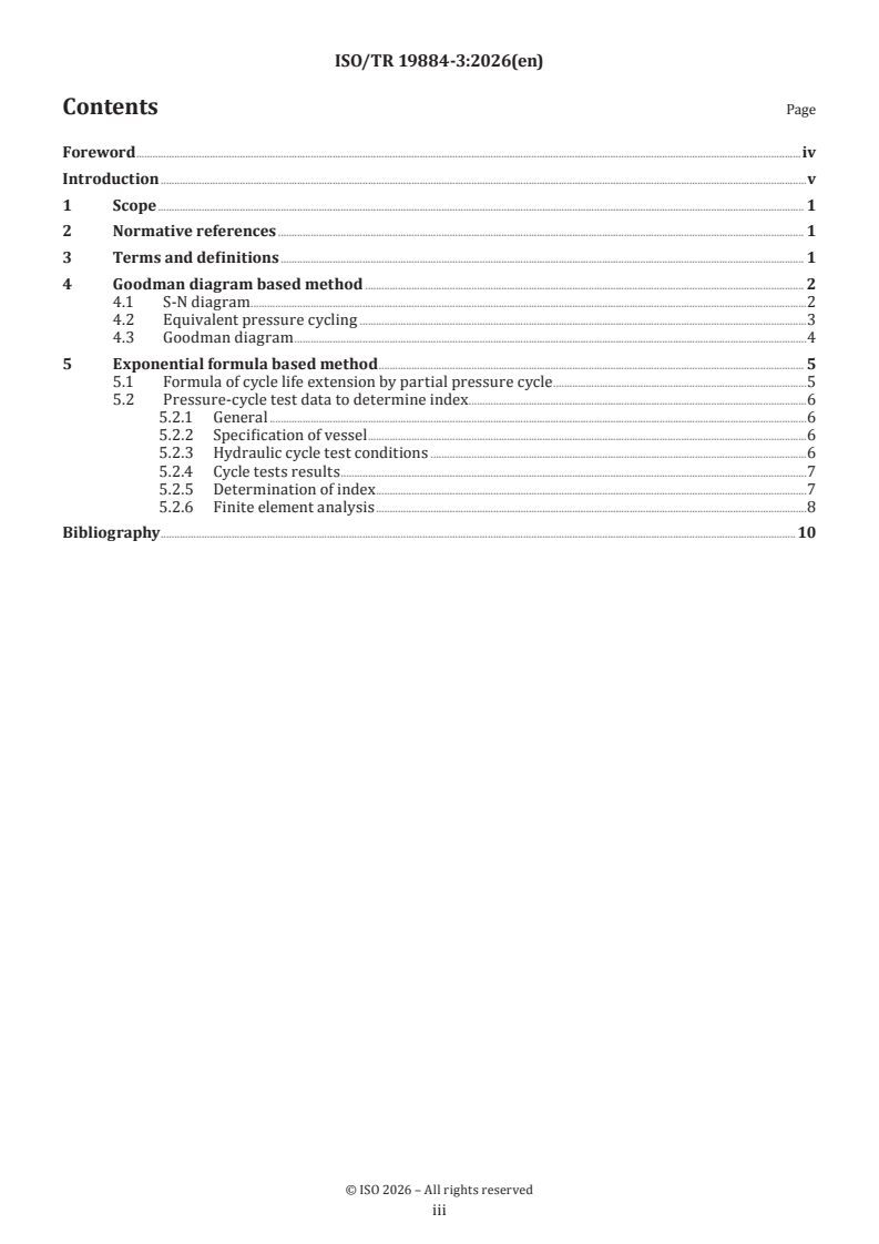
Contents Page
Foreword .iv
Introduction .v
1 Scope . 1
2 Normative references . 1
3 Terms and definitions . 1
4 Goodman diagram based method . 2
4.1 S-N diagram .2
4.2 Equivalent pressure cycling .3
4.3 Goodman diagram .4
5 Exponential formula based method . 5
5.1 Formula of cycle life extension by partial pressure cycle .5
5.2 Pressure-cycle test data to determine index .6
5.2.1 General .6
5.2.2 Specification of vessel .6
5.2.3 Hydraulic cycle test conditions .6
5.2.4 Cycle tests results .7
5.2.5 Determination of index .7
5.2.6 Finite element analysis .8
Bibliography .10
iii
Foreword
ISO (the International Organization for Standardization) is a worldwide federation of national standards
bodies (ISO member bodies). The work of preparing International Standards is normally carried out through
ISO technical committees. Each member body interested in a subject for which a technical committee
has been established has the right to be represented on that committee. International organizations,
governmental and non-governmental, in liaison with ISO, also take part in the work. ISO collaborates closely
with the International Electrotechnical Commission (IEC) on all matters of electrotechnical standardization.
The procedures used to develop this document and those intended for its further maintenance are described
in the ISO/IEC Directives, Part 1. In particular, the different approval criteria needed for the different types
of ISO document should be noted. This document was drafted in accordance with the editorial rules of the
ISO/IEC Directives, Part 2 (see www.iso.org/directives).
ISO draws attention to the possibility that the implementation of this document may involve the use of (a)
patent(s). ISO takes no position concerning the evidence, validity or applicability of any claimed patent
rights in respect thereof. As of the date of publication of this document, ISO had not received notice of (a)
patent(s) which may be required to implement this document. However, implementers are cautioned that
this may not represent the latest information, which may be obtained from the patent database available at
www.iso.org/patents. ISO shall not be held responsible for identifying any or all such patent rights.
Any trade name used in this document is information given for the convenience of users and does not
constitute an endorsement. For an explanation of the voluntary nature of standards, the meaning of ISO
specific terms and expressions related to conformity assessment, as well as information about ISO's
adherence to the World Trade Organization (WTO) principles in the Technical Barriers to Trade (TBT), see
www.iso.org/iso/foreword.html.
This document was prepared by Technical Committee 197, Hydrogen technologies.
A list of all parts in the ISO 19884 series can be found on the ISO website.
Any feedback or questions on this document should be directed to the user’s national standards body. A
complete listing of these bodies can be found at www.iso.org/members.html.
iv
Introduction
A much higher level of long-term reliability is required for a pressure vessel in stationary use compared
to on-board use, as the risk of a serious incident in the event of a vessel rupture is significantly higher.
Reliability is ensured through full-pressure cycle testing in accordance with the performance-based
[1]
standard, ISO 19884-1 . One of the primary objectives of utilizing stationary vessels is to accumulate
hydrogen pressure quickly prior to refuelling vehicles. That is why the pressure of a stationary vessel never
decreases to zero in actual use. The expected pressurizing time-history is between the design pressure and
70% of the design pressure, that is, a partial pressure cycle, for which a longer cycle life is expected than
the full pressure cycle life. The cycle life extension by the partial pressure cycle seems applicable to other
high-pressure hydrogen equipment, such as tubes. Cycle life extension is rather a matter of maintenance for
reliable performance. The authority with jurisdiction needs to be convinced that the vessel can be relied
upon for a period longer than the nameplate life. This document presents candidate methods for estimating
cycle life extension through partial pressure cycling for authorities and users, enabling hydrogen stations
to be operated and managed efficiently and safely. This document presents the currently available methods
and the test data to support them. However, this document is not intended to inhibit the advancement of new
technologies that are presently being developed or used in the market, or those yet to emerge. As these new
technologies mature, they will be added in future revisions of this document.
v
Technical Report ISO/TR 19884-3:2026(en)
Gaseous hydrogen — Pressure vessels for stationary
storage —
Part 3:
Pressure cycle test data to demonstrate partial pressure cycle
estimation methods
1 Scope
This document describes detailed methods for evaluating cycle life extension by partial pressure cycles with
necessary conditions and example data of their application.
Two methods for evaluating cycle life extension by partial pressure cycles based on the Goodman diagram
[1]
and exponential formula are presented in ISO 19884-1 . These methods do not rely on fracture mechanical
[1]
methodology but on pressurizing cycle test data, since the framework of ISO 19884-1 is constructed on
performance demonstrated by pressurizing cycle test data in hydrogen.
2 Normative references
There are no normative references in this document.
3 Terms and definitions
For the purposes of this document, the following terms and definitions apply.
ISO and IEC maintain terminology databases for use in standardization at the following addresses:
— ISO Online browsing platform: available at https:// www .iso .org/ obp
— IEC Electropedia: available at https:// www .electropedia .org/
3.1
Class A material
material known to have no significant or unanticipated changes in its performance or mechanical properties
when exposed to gaseous hydrogen under the listed service conditions
3.2
design pressure
pressure used in the design of the vessel for the purposes of establishing the minimum thickness of the
pressure shell for the stated cycle life and service conditions
3.3
full pressure cycle
cycle of pressure amplitude greater than 100% of the design pressure (3.2) to less than 10% of the design
pressure (3.2)
3.4
full pressure cycle life
maximum number of full pressure cycles in hydrogen service that the pressure vessel is designed to
withstand in service
3.5
mean stress
average of the maximum value and the minimum value of repeated stress
3.6
partial pressure cycle
cycle of pressure amplitude smaller than full pressure cycle (3.3) keeping the maximum pressure lower than
or equal to the design pressure (3.2)
3.7
partial pressure cycle life
maximum number of partial pressure cycles (3.6) that the pressure vessel is designed to withstand in
hydrogen service
3.8
pressure differential
difference between the maximum value and the minimum value of repeated pressure
3.9
stress amplitude
half (1/2) of the difference between the maximum value and the minimum value of repeated stress
4 Goodman diagram based method
4.1 S-N diagram
The S-N diagram has been commonly used for the prediction of fatigue life of metallic specimens. The
Goodman diagram has also been employed to take into account the effect of the mean stress of the stress
cycle on the fatigue life of the specimen. The Miner’s rule has been regarded as valid for the fatigue life
prediction of the specimen in the case of variational stress amplitude. These methods have been developed
in the research of fatigue life of metals, especially of steel. In line with the research and development history
of fatigue life, these methods seem fit for Type 1 pressure vessels, Type 2 pressure vessels, and Type 3
pressure vessels, where the critical failure modes are fatigue crack penetration in the metallic shell. The
merit of these methods can be applied to Type 4 pressure vessels, which consist of a metallic boss, a plastic
liner, and a composite.
The pressure vessel manufacturer is responsible for developing the S-N diagram using the same materials
and manufacturing approach used for the Type 4 pressure vessels. As this is an S-N diagram to evaluate
fatigue characteristics of the composite, the failure mode needs to be consistent, e.g. always composite
failure for a Type 4 pressure vessel (i.e. burst, not liner leakage).
The following steps must be used for a Type 4 vessel:
a) Establish the mean burst pressure of a vessel for which an S -N diagram is to be developed. A minimum
of 4 units of the vessel is required to achieve this. Plot this point as 100 % stress, 1 cycle on the S-N
diagram.
b) Cycle a minimum of 4 units from no more than 10 % of the design pressure to a first specified pressure
level for which the stress is known. Plot this point on the S-N diagram. The S value will be a stress
relative to the mean burst, and the
...