

ISO 21815-4:2026
(Main)Earth-moving machinery — Collision warning and avoidance — Part 4: Risk area and risk level for swing and rotation motion
- Abstract
This document specifies requirements for collision warning systems (CWS) and collision avoidance systems (CAS) that address swing and rotation motion for: earth moving machinery as defined in ISO 6165; mobile underground mining machinery as defined in ISO 19296; rock drill rigs as defined in ISO18758-1; road construction machinery as defined in ISO 22242. This document covers the risk of collision with an intended object between the ground plane of the machine and the top of the machine operator cabin. This document does not cover the risk of collision with parts of the intended objects that are higher than the top of the machine operator cabin. This document does not consider machine height of working tool (e.g. height of boom and arm). This document covers collision avoidance by motion inhibition or collision warning by providing warning to the operator, prior to initiation of swing and rotation motion around vertical axis of a machine (e.g. excavators) or swing and rotation parts of a machine about an axis (e.g. backhoe portion of backhoe loaders, conveyer part of mobile screens, booms on rock drills). It does not cover collision avoidance by automatic application of the braking or automatic manoeuvring (e.g. raise bucket) away from the intended object. The system described in this document is intended to assist the operator of the machine. The responsibility for safe operation of the machine remains with the machine operator. This document is not applicable to collision warning and collision avoidance systems installed/manufactured before the date of its publication. For the purpose of this document, the term "machine" means swing and rotation machine or swing and rotation parts of machine.
- Status
- Published
- Publication Date
- 12-Nov-2026
- Technical Committee
- ISO/TC 127/SC 2 - Safety, ergonomics and general requirements
- Drafting Committee
- ISO/TC 127/SC 2 - Safety, ergonomics and general requirements
- Current Stage
- 6060 - International Standard published
- Start Date
- 13-Nov-2026
- Completion Date
- 13-Nov-2026
ISO 21815-4 is an ISO standard for collision warning and avoidance on earth-moving machinery, focused on swing and rotation motion. It specifies how collision warning systems (CWS) and collision avoidance systems (CAS) assess collision risk area and collision risk level (CRL), then warn the operator or inhibit motion before rotation starts. It is intended for machine manufacturers, system integrators, operators, service providers, and safety bodies that need a common basis for managing this kind of collision risk.
What does ISO 21815-4 specify?
ISO 21815-4 specifies requirements for CWS and CAS on earth-moving machinery, mobile underground mining machinery, rock drill rigs, and road construction machinery. It focuses on intended objects between the ground plane of the machine and the top of the operator cabin, and it covers swing and rotation motion of the machine or of machine parts.
The document excludes collision with parts of the intended object above the cabin top and does not address the height of the work tool, such as boom or arm height. It also does not cover avoidance by automatic braking or automatic manoeuvring away from the intended object. The system is intended to assist the operator, while the operator remains responsible for safe operation.
The document is organized into six clauses, followed by informative and normative annexes.
| Annex | What it covers |
|---|---|
| Annex A | CRL by rotation angle with a stationary object |
| Annex B | CRLs by distance with a moving object |
| Annex C | Example calculation of CxS distance with a moving object |
| Annex D | Normative limitations of use of CxS |
| Annex E | Estimating the path |
| Annex F | Comparison of machine motions |
What are the key requirements of ISO 21815-4?
ISO 21815-4 requires the machine and its collision warning and avoidance system (CxS) to be designed so that swing or rotation can be controlled before a collision occurs. In practice, that means the system must identify intended objects, assign a CRL, and trigger the right warning or avoidance action early enough to be useful.
System design and risk area
Clause 4.1 requires the machine to meet the safety requirements in the clause and to follow ISO 12100 for relevant hazards that are not specifically covered. The CxS must comply with ISO 21815-1 unless ISO 21815-4 adds or changes the requirement.
Clause 4.2 says the CxS distance for swing and rotation must be large enough to inhibit the start of rotation before contact with an intended object. The standard uses two calculation cases:
- rotation angle with a stationary object
- distance when the intended object moves toward the machine
In practice, the designer must choose the method that matches the application. If a system uses a reduced collision risk area, or several selectable configurations, the operator’s manual has to state those limits clearly.
The collision risk area is normally based on the maximum reach of the work equipment, but it can be reduced if the system uses real-time kinematics, barriers, or path information. That matters because many sites use only part of the machine envelope, and a well-chosen zone can reduce nuisance alarms without hiding real risk.
How CRL is determined
Clause 4.3 says the CxS must determine a CRL when it detects each intended object in the detection zone or collision risk area. If the system evaluates both the rotation angle and the distance from the rotation center, the overall CRL is the higher of the two results.
Annex A and Annex B explain the two CRL methods. Annex A covers the stationary-object case, where the key question is whether the current path will reach the object if rotation starts. Annex B covers the moving-object case, where the object moves toward the machine and the distance-based CRL changes with that movement.
Clause 4.3 also notes that combined motion must be considered when swing and rotation is used together with track steering motion. For that case, the document points to ISO 21815-5. Annex F helps by comparing machine motions and showing which part of the ISO 21815 series applies.
Annex D is normative and says multiple intended objects must each be analyzed, assigned a risk level, and handled appropriately. That matters on busy sites, where the closest object is not always the only one that can create a hazard.
Warning, avoidance, and operator information
Clause 4.4 limits system action to intended objects in the collision risk area. That helps avoid unnecessary responses to objects that are not relevant to the motion being controlled.
Clause 4.5 requires the CxS to provide either a warning for a CWS or an intervening collision avoidance action for a CAS before swing and rotation begins. The example avoidance action in the document is rotation motion inhibition (RMI). Clause 4.6 and 4.7 then direct the reader to the CWS and CAS requirements in ISO 21815-3.
Clause 5 says time and distance calculation follows ISO 21815-3. Annex C shows how that calculation is broken into detection, determination, action, completed inhibition, and safe distance. For design and verification work, this is the part that ties sensor response, operator reaction, and machine stopping behavior together.
Clause 6 requires information for use in the operator’s manual in line with ISO 12100 and taking ISO 6750-1 into account. The manual must include symbol explanations, error messages, warning messages, calibration procedures, and the system limitations. In practice, that is what allows the operator to understand the alarms and know when the system is operating within its intended limits.
What terms does ISO 21815-4 define?
- Collision warning and avoidance system (CxS) - the overall system that detects intended objects, evaluates risk, and provides warning or avoidance action.
- Collision warning system (CWS) - a CxS function that warns the operator before swing or rotation starts.
- Collision avoidance system (CAS) - a CxS function that intervenes automatically before swing or rotation starts, for example by motion inhibition.
- Collision risk level (CRL) - the level assigned to an intended object from its position and motion relative to the machine.
- Intended object - the object being evaluated as a possible collision partner, such as a person, barrier, or vehicle.
- Rotation motion inhibition (RMI) - the avoidance action that prevents rotational motion from starting.
- Detection zone - the area used by the system to detect intended objects before it decides on warning or avoidance action.
Who uses ISO 21815-4?
ISO 21815-4 is used by machine manufacturers who design swing and rotation machines and by system integrators who configure the detection zone, risk area, and action logic. It is also used by providers of collision warning and avoidance technology that build sensors, software, and operator interfaces.
Machine users and employers use it to understand what the system should do on site and what limitations must be described in the manual. Service providers use it when supporting calibration, setup, and maintenance. Health and safety bodies, accident prevention organizations, and market surveillance authorities use it when assessing whether a machine’s collision warning or avoidance function matches the standard’s approach.
Which standards are used with ISO 21815-4?
- ISO 6750-1 - provides the contents and format framework for the operator’s manual.
- ISO 12100 - gives the general principles for risk assessment and risk reduction.
- ISO 21815-1 - provides general requirements for collision warning and avoidance systems and the base definitions used here.
- ISO 21815-3 - supplies the detailed CWS and CAS requirements, plus the time and distance calculation basis used by this part.
- ISO 21815-5 - covers other motions and provides examples and parameters for track steering motion and related combined-motion cases.
What does the ISO 21815-4 document contain?
ISO 21815-4 contains performance requirements, calculation methods, and guidance material for swing and rotation collision risk management. The main text includes illustrative figures for different machine layouts, including 360-degree rotation and limited-angle rotation, so readers can relate the requirements to machine geometry.
Annex C is the most calculation-focused part. It lays out a worked example of CxS distance using labeled points and intervals, and it separates detection, determination, action, motion inhibition, and safe distance. Annex A and Annex B give the logic for assigning CRLs in stationary-object and moving-object cases, while Annex E explains possible path and expected path. Annex F summarizes motion types and typical machine examples so designers and integrators can map a machine to the correct part of the ISO 21815 series.
Frequently Asked Questions
ISO 21815-4:2026 is a standard published by the International Organization for Standardization (ISO). Its full title is "Earth-moving machinery — Collision warning and avoidance — Part 4: Risk area and risk level for swing and rotation motion". This standard covers: This document specifies requirements for collision warning systems (CWS) and collision avoidance systems (CAS) that address swing and rotation motion for: earth moving machinery as defined in ISO 6165; mobile underground mining machinery as defined in ISO 19296; rock drill rigs as defined in ISO18758-1; road construction machinery as defined in ISO 22242. This document covers the risk of collision with an intended object between the ground plane of the machine and the top of the machine operator cabin. This document does not cover the risk of collision with parts of the intended objects that are higher than the top of the machine operator cabin. This document does not consider machine height of working tool (e.g. height of boom and arm). This document covers collision avoidance by motion inhibition or collision warning by providing warning to the operator, prior to initiation of swing and rotation motion around vertical axis of a machine (e.g. excavators) or swing and rotation parts of a machine about an axis (e.g. backhoe portion of backhoe loaders, conveyer part of mobile screens, booms on rock drills). It does not cover collision avoidance by automatic application of the braking or automatic manoeuvring (e.g. raise bucket) away from the intended object. The system described in this document is intended to assist the operator of the machine. The responsibility for safe operation of the machine remains with the machine operator. This document is not applicable to collision warning and collision avoidance systems installed/manufactured before the date of its publication. For the purpose of this document, the term "machine" means swing and rotation machine or swing and rotation parts of machine.
This document specifies requirements for collision warning systems (CWS) and collision avoidance systems (CAS) that address swing and rotation motion for: earth moving machinery as defined in ISO 6165; mobile underground mining machinery as defined in ISO 19296; rock drill rigs as defined in ISO18758-1; road construction machinery as defined in ISO 22242. This document covers the risk of collision with an intended object between the ground plane of the machine and the top of the machine operator cabin. This document does not cover the risk of collision with parts of the intended objects that are higher than the top of the machine operator cabin. This document does not consider machine height of working tool (e.g. height of boom and arm). This document covers collision avoidance by motion inhibition or collision warning by providing warning to the operator, prior to initiation of swing and rotation motion around vertical axis of a machine (e.g. excavators) or swing and rotation parts of a machine about an axis (e.g. backhoe portion of backhoe loaders, conveyer part of mobile screens, booms on rock drills). It does not cover collision avoidance by automatic application of the braking or automatic manoeuvring (e.g. raise bucket) away from the intended object. The system described in this document is intended to assist the operator of the machine. The responsibility for safe operation of the machine remains with the machine operator. This document is not applicable to collision warning and collision avoidance systems installed/manufactured before the date of its publication. For the purpose of this document, the term "machine" means swing and rotation machine or swing and rotation parts of machine.
ISO 21815-4:2026 is classified under the following ICS (International Classification for Standards) categories: 53.100 - Earth-moving machinery. The ICS classification helps identify the subject area and facilitates finding related standards.
ISO 21815-4:2026 is available in PDF format for immediate download after purchase. The document can be added to your cart and obtained through the secure checkout process. Digital delivery ensures instant access to the complete standard document.
Standards Content (Sample)
International
Standard
ISO 21815-4
First edition
Earth-moving machinery —
2026-11
Collision warning and avoidance —
Part 4:
Risk area and risk level for swing
and rotation motion
Engins de terrassement — Avertissement et évitement de
collision —
Partie 4: Zone de risque et niveau de risque pour les mouvements
d'orientation et rotation
Reference number
© ISO 2026
All rights reserved.
This ISO publication is protected by copyright and is owned by ISO and/or its licensors.
The content of this ISO publication is provided under licence, not sold. Use is subject to the applicable licence terms issued by ISO,
an ISO member body, or an authorized third-party distributor.
Except as required for implementation or expressly permitted by a separate licence, no part of this ISO publication may be
reproduced, distributed, modified, used, or made available in any form or by any means – electronic or mechanical, including
photocopying, scanning, recording, or posting on internal or external digital platforms.
Any use beyond the scope of the granted rights is prohibited and may result in legal action.
ISO copyright office
CP 401 • CH-1214 Vernier, Geneva
Phone: +41 22 749 01 11
Email: copyright@iso.org
Website: www.iso.org
Published in Switzerland
ii
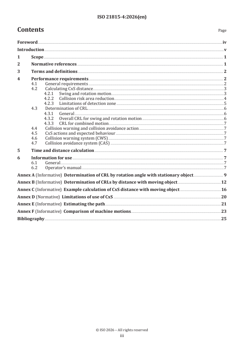
Contents Page
Foreword .iv
Introduction .v
1 Scope . 1
2 Normative references . 1
3 Terms and definitions . 2
4 Performance requirements . . 2
4.1 General requirements .2
4.2 Calculating CxS distance .3
4.2.1 Swing and rotation motion.3
4.2.2 Collision risk area reduction.4
4.2.3 Limitations of detection zone .5
4.3 Determination of CRL .6
4.3.1 General .6
4.3.2 Overall CRL for swing and rotation motion .6
4.3.3 CRL for combined motion .7
4.4 Collision warning and collision avoidance action .7
4.5 CxS actions and expected behaviour .7
4.6 Collision warning system (CWS) .7
4.7 Collision avoidance system (CAS) .7
5 Time and distance calculation . 7
6 Information for use . 7
6.1 General .7
6.2 Operator’s manual .7
Annex A (Informative) Determination of CRL by rotation angle with stationary object . 9
Annex B (Informative) Determination of CRLs by distance with moving object .12
Annex C (Informative) Example calculation of CxS distance with moving object .16
Annex D (Normative) Limitations of use of CxS .20
Annex E (Informative) Estimating the path .21
Annex F (Informative) Comparison of machine motions.23
Bibliography .25
iii
Foreword
ISO (the International Organization for Standardization) is a worldwide federation of national standards
bodies (ISO member bodies). The work of preparing International Standards is normally carried out through
ISO technical committees. Each member body interested in a subject for which a technical committee
has been established has the right to be represented on that committee. International organizations,
governmental and non-governmental, in liaison with ISO, also take part in the work. ISO collaborates closely
with the International Electrotechnical Commission (IEC) on all matters of electrotechnical standardization.
The procedures used to develop this document and those intended for its further maintenance are described
in the ISO/IEC Directives, Part 1. In particular, the different approval criteria needed for the different types
of ISO document should be noted. This document was drafted in accordance with the editorial rules of the
ISO/IEC Directives, Part 2 (see www.iso.org/directives).
ISO draws attention to the possibility that the implementation of this document may involve the use of (a)
patent(s). ISO takes no position concerning the evidence, validity or applicability of any claimed patent
rights in respect thereof. As of the date of publication of this document, ISO had not received notice of (a)
patent(s) which may be required to implement this document. However, implementers are cautioned that
this may not represent the latest information, which may be obtained from the patent database available at
www.iso.org/patents. ISO shall not be held responsible for identifying any or all such patent rights.
Any trade name used in this document is information given for the convenience of users and does not
constitute an endorsement.
For an explanation of the voluntary nature of standards, the meaning of ISO specific terms and expressions
related to conformity assessment, as well as information about ISO's adherence to the World Trade
Organization (WTO) principles in the Technical Barriers to Trade (TBT), see www.iso.org/iso/foreword.html.
This document was prepared by Technical Committee ISO/TC 127, Earth-moving machinery, Subcommittee
SC 2, Safety, ergonomics and general requirements.
A list of all parts in the ISO 21815 series can be found on the ISO website.
Any feedback or questions on this document should be directed to the user’s national standards body. A
complete listing of these bodies can be found at www.iso.org/members.html
iv
Introduction
The increasing use of detection systems and avoidance technology has been supporting operators to
safely operate machines in the field of mining and construction. At the same time, there are demands to
set standards for machines and systems detecting, alerting and intervening to mitigate collision risk. This
document addresses collision risk areas and collision risk levels (CRLs) for machines utilizing detection
systems and avoidance technology in the area of earth-moving machinery that exhibit swing and rotation
motion.
This document is a type-C standard as stated in ISO 12100.
This document is of relevance, in particular, for the following stakeholder groups representing the market
players with regard to machinery safety:
— machine manufacturers (small, medium and large enterprises);
— health and safety bodies (regulators, accident prevention organisations, market surveillance etc.).
Others can be affected by the level of machinery safety achieved with the means of the document by the
above-mentioned stakeholder groups:
— machine users /employers (small, medium and large enterprises);
— machine users /employees (e.g. trade unions, organizations for people with special needs);
— service providers, e. g. for maintenance (small, medium and large enterprises);
— providers of collision warning and avoidance technology;
— system integrators.
The above-mentioned stakeholder groups have been given the possibility to participate at the drafting
process of this document.
The machinery concerned and the extent to which hazards, hazardous situations, or hazardous events are
covered are indicated in the scope of this document.
When requirements of this type-C standard are different from those which are stated in type-A or type-B
standards, the requirements of this type-C standard take precedence over the requirements of the other
standards for machines that have been designed and built according to the requirements of this type-C
standard.
The intention of this document is to address requirements for detecting, alerting and intervention in
mitigating collision risk.
There are currently two standards addressing object detection in the earth moving machinery field:
ISO 16001 and ISO 17757. These standards provide guidance for visibility aids and object detection system
and for autonomous and semi-autonomous machines, however, there is currently no standard that describes
collision risk awareness, warning signals and collision avoidance actions of manually operated machinery
when there is a risk of collision.
v
International Standard ISO 21815-4:2026(en)
Earth-moving machinery — Collision warning and
avoidance —
Part 4:
Risk area and risk level for swing and rotation motion
1 Scope
This document specifies requirements for collision warning systems (CWS) and collision avoidance systems
(CAS) that address swing and rotation motion for:
— earth moving machinery as defined in ISO 6165;
— mobile underground mining machinery as defined in ISO 19296;
— rock drill rigs as defined in ISO18758-1;
— road construction machinery as defined in ISO 22242.
This document covers the risk of collision with an intended object between the ground plane of the machine
and the top of the machine operator cabin. This document does not cover the risk of collision with parts of
the intended objects that are higher than the top of the machine operator cabin. This document does not
consider machine height of working tool (e.g. height of boom and arm).
This document covers collision avoidance by motion inhibition or collision warning by providing warning
to the operator, prior to initiation of swing and rotation motion around vertical axis of a machine (e.g.
excavators) or swing and rotation parts of a machine about an axis (e.g. backhoe portion of backhoe loaders,
conveyer part of mobile screens, booms on rock drills).
It does not cover collision avoidance by automatic application of the braking or automatic manoeuvring (e.g.
raise bucket) away from the intended object.
The system described in this document is intended to assist the operator of the machine. The responsibility
for safe operation of the machine remains with the machine operator.
This document is not applicable to collision warning and collision avoidance systems installed/manufactured
before the date of its publication.
For the purpose of this document, the term "machine" means swing and rotation machine or swing and
rotation parts of machine.
2 Normative references
The following documents are referred to in the text in such a way that some or all of their content constitutes
requirements of this document. For dated references, only the edition cited applies. For undated references,
the latest edition of the referenced document (including any amendments) applies.
ISO 6750-1, Earth-moving machinery — Operator's manual — Part 1: Contents and format
ISO 12100, Safety of machinery — General principles for design — Risk assessment and risk reduction
ISO 21815-1, Earth-moving machinery — Collision warning and avoidance — Part 1: General requirements
ISO 21815-3, Earth-moving machinery — Collision warning and avoidance — Part 3: Risk area and risk level for
forward/reverse motion
ISO 21815-5, Earth-moving machinery — Collision warning and avoidance — Part 5: Risk area and risk level for
other motions
3 Terms and definitions
For the purposes of this document, the terms and definitions given in ISO 21815-1, ISO 21815-3, and
ISO 21815-5 apply.
ISO and IEC maintain terminological databases for use in standardization at the following addresses:
— ISO Online browsing platform: available at https:// www .iso .org/ obp
— IEC Electropedia: available at https:// www .electropedia .org/
4 Performance requirements
4.1 General requirements
Machinery shall conform with the safety requirements and/or protective/risk reduction measures of this
clause. In addition, the machine shall be designed according to the principles of ISO 12100 for relevant, but
not significant hazards which are not dealt with by this document.
CxS, as defined in ISO 21815-1:2022 3.10, shall conform to the requirements of ISO 21815-1, in as far as those
are not modified or added to by the requirements in this document.
The CxS shall determine a collision risk level (CRL)of each intended object and communicate the appropriate
action.
The CxS must re-evaluate the risk level at a frequency high enough to address the relative movement of the
machine and intended objects.
Since this document deals with inhibition of rotational motion, this section defines the CxS requirements
related to inhibiting the initiation of motion prior to machine rotation.
The detection zone of CxD, as defined in ISO 21815-1:2022 3.15, should be the same or larger than the
collision risk area. However, due to limits of the system, the detection zone can be smaller than the collision
risk area.
Some CxS products can have limited detection zone to maximum reach of work equipment while other
products have "only around the tail of rotating machine that is out of the operator's field of vision''. In such
cases, the limits of the system and the selection of detection zone according to the application shall be
defined in the information for use as system limitations.
This document illustrates excavator-type machine which rotates 360° (e.g. see Figure 1). However, machines
with swing and rotation angle limited to less than 360° (e.g. backhoe loader in Figure 2) are also covered in
this document.
Key
1 maximum reach
Figure 1 — Excavator-type machine which rotates 360°
Key
1 maximum reach
Figure 2 — Machines where swing and rotation angle is limited to less than 360°
4.2 Calculating CxS distance
4.2.1 Swing and rotation motion
The CxS distance for swing and rotation motion shall be large enough to allow the machine to inhibit
initiation of rotation to avoid a collision with an intended object.
There are two cases considered for calculating CxS distances.
— Rotation angle with stationary object: when there is a risk of collision due to the presence of a stationary
intended object before the start of machine rotation.
— Distance when moving object exists: when the intended object itself moves and comes towards the
machine and increases the risk of collision.
An appropriate CxS distance calculation method shall be selected according to the application.
NOTE 1 A CxS distance calculation example for distance with moving object is shown in Annex C.
NOTE 2 The CxS distance for rotation angle with stationary object depends on the type, size and performance of
the machine. This document does not contain requirements for this case due to the wide variation of the possibilities.
Avoidance and warnings can be provided by CxS after initiation of rotational motion but are not addressed
in this document.
4.2.2 Collision risk area reduction
The collision risk area should be sized as maximum reach of work equipment (e.g. boom, arm and bucket). The
collision risk area is determined by the physical kinematics (e.g. speed, turning radius, angle, dimensions)
limitations of the machine. The size of the collision risk area may be reduced by knowing the real-time value
of kinematics (e.g. speed, turning angle). Physical or virtual barriers can reduce the collision risk area if the
CxS is capable of considering them. CxS, which has the ability to utilize information regarding projected path
and expected path and their interactions, may possibly reduce the size of the collision risk area, and multiple
configurations may be provided for an operator to select. If CxS is configured for a collision risk area that is
not the maximum reach of the work equipment, the collision risk area shall be stated in the information for
use. Additionally, if multiple collision risk area configurations are possible, the configurations and collision
risk areas shall be stated in the information of use.
Expected path is shown in Annex E.
NOTE The expected path of work equipment cannot be estimated since operator’s future action (intention) cannot
be predicted even when rotation machine can provide the actual real-time value of work equipment position by the
actual real-time value of kinematics (e.g. arm angle, boom angle, turning angle). The collision risk area should be sized
as maximum reach of work equipment.
Figure 3 shows an example of expected path for unpredictable case: when the operator swings/rotates
without changing the arm angle and boom angle. Figure 4 shows an example of expected path for
unpredictable case. Prior to initiation of rotational motion, both cases are possible.
Key
1 expected path
2 collision risk area
3 intended object
4 maximum reach
Figure 3 — Example of expected path for unpredictable case-1
Key
1 expected path
2 collision risk area
3 intended object
4 maximum reach
Figure 4 — Example of expected path for unpredictable case-2
4.2.3 Limitations of detection zone
In some cases, the rotational machine is used at the work site that is restricted in size and space available
where some objects (e.g. humans) exist inside the maximum reach of work equipment or the machine works
without extending boom/arm to maximum reach of the machine. Frequent nuisance alarms occur when
setting excessively large detection zones (e.g. maximum reach of machine) for a work site that is restricted
in size and available space. Improper settings can create alarm fatigue and result in operators ignoring real
collision risks.
Operators can recognize intended objects (e.g. humans) within their direct field of view, but the areas
outside the operator’s direct field of view (e.g. around the tail of the rotational structure) are the areas of
potentially elevated collision risk. Figure 5 show the example of setting detection zone that visibility can
be limited (in case that operator cabin is located at left side of rotational structure). Therefore, for practical
and effective use of CxS, detection zones may be set around certain collision risk areas only (e.g. outside the
operator’s direct field of view, around the tail of rotational machine) by the system integrator.
NOTE The detection zone moves with the movement of the machine's rotational structure
When setting the detection zone to a specific area, the shape of the collision risk area is not limited to a
concentric circle determined by the radial distance from the centre of rotation. In that case, it can be
formed at a distance from the outer peripheral surface of the upper rotational structure. Limitations such
as detection zone and shape of collision risk area shall be appropriately specified by the system integrator
according to the application and shall be described in the operator’s manual as a system limitation.
Key
1 detection zone (shaded area)
2 intended object outside the direct field of view of the operator
3 possible path
4 operator cabin
5 intended object in direct field of view of the operator
NOTE Figure 5 shows an example of setting a detection zone near the machine tail outside the direct field of view
of the operator (in case that operator
...