

ISO 7554-1:2026
(Main)Surgical instruments — Terms, measuring methods and test methods — Part 1: Vocabulary
- Abstract
This document defines terms for surgical instruments and their components.
- Status
- Published
- Publication Date
- 27-Aug-2026
- Technical Committee
- ISO/TC 170 - Surgical instruments
- Drafting Committee
- ISO/TC 170 - Surgical instruments
- Current Stage
- 6060 - International Standard published
- Start Date
- 28-Aug-2026
- Due Date
- 14-Dec-2026
- Completion Date
- 28-Aug-2026
ISO 7554-1:2026 is an ISO International Standard that defines the vocabulary for surgical instruments and their components. Although the series title mentions measuring methods and test methods, Part 1 itself is the vocabulary part, so it standardizes names, forms and parts rather than test procedures. Engineers, quality staff and buyers use it to describe instruments consistently in specifications, drawings, catalogs and records.
What does ISO 7554-1:2026 specify?
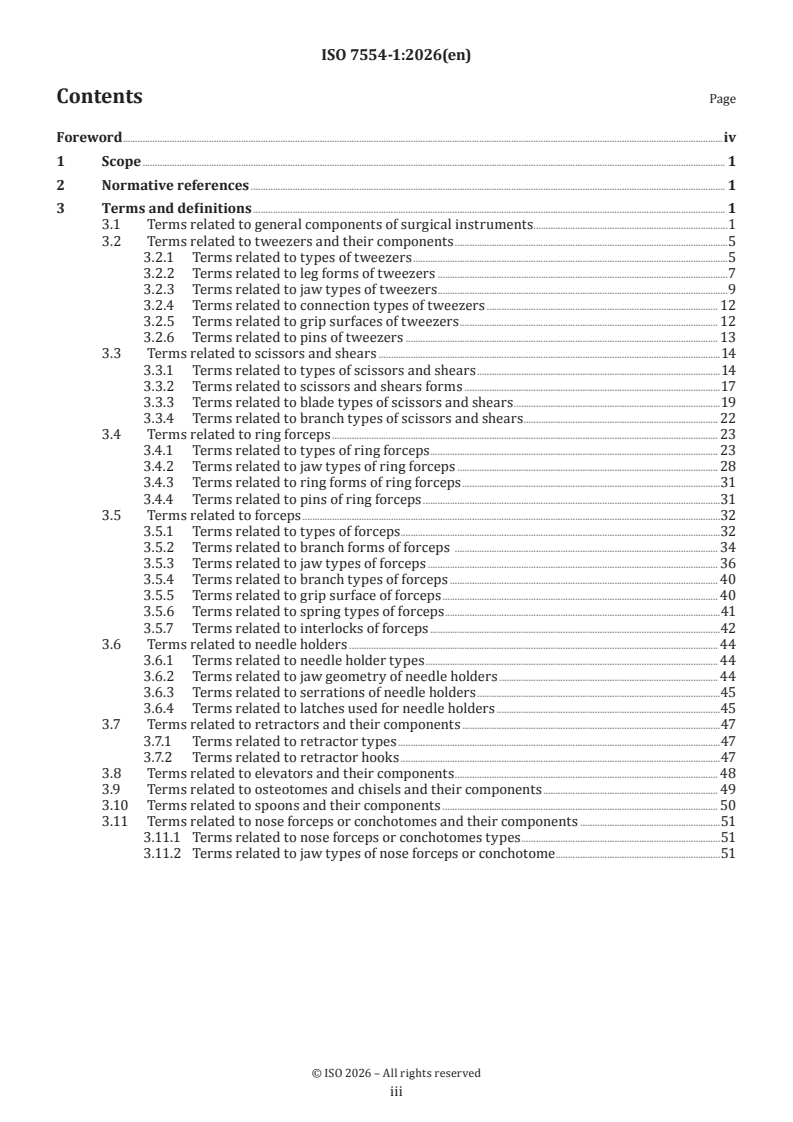
ISO 7554-1:2026 defines terms for surgical instruments and their components. Clause 1 gives the scope, Clause 2 covers normative references, and Clause 3 contains the terms and definitions.
The document is organized as a vocabulary by instrument family and by component type. It starts with general parts and then groups terms for tweezers, scissors and shears, ring forceps, forceps, needle holders, retractors, elevators, osteotomes and chisels, spoons, and nose forceps or conchotomes.
| Clause | What it covers |
|---|---|
| 1 | Scope |
| 2 | Normative references |
| 3.1 | General components of surgical instruments |
| 3.2 | Tweezers and their components |
| 3.3 | Scissors and shears |
| 3.4 | Ring forceps |
| 3.5 | Forceps |
| 3.6 | Needle holders |
| 3.7 | Retractors and their components |
| 3.8 | Elevators and their components |
| 3.9 | Osteotomes and chisels and their components |
| 3.10 | Spoons and their components |
| 3.11 | Nose forceps or conchotomes and their components |
What are the key requirements of ISO 7554-1:2026?
ISO 7554-1:2026 is a terminology standard, so its main function is to fix the meaning of common surgical-instrument names. In practice, that matters because the same word can describe different shapes or locking features unless the terminology is controlled.
General component terms in Clause 3.1
Clause 3.1 defines the basic parts used across many instrument types, such as working end, distal end, proximal end, jaw, branch, joint, ring, serration, lock, latch, interlock, guiding pin and set screw. It also covers features like cutting edge, blade, hook, horn, groove, fenestration, stop pin and leaf spring.
This helps teams describe the same instrument part in the same way across drawings, specifications and inspection reports. It is especially useful when one instrument family shares parts with another, because the document gives a common base vocabulary.
Tweezers terms in Clause 3.2
Clause 3.2 classifies tweezers by locking method, leg form, jaw type, connection type, grip surface and pins. It includes forms such as tweezers with guiding pin, spring lock, pin lock and set screw, plus leg forms like straight, bent, double-bent, knee-angled, bayonet-shaped and crossed.
It also distinguishes jaw and grip features such as smooth jaws, anatomical windowed jaws, serrated jaws, cross-grooved grip surfaces, and guiding pin or stop pin arrangements. In practice, this lets a purchaser or designer specify the exact tweezer geometry needed for handling, closure control and tissue grip.
Scissors and shears terms in Clause 3.3
Clause 3.3 covers scissors with rings, shears with branches and leaf springs, plaster scissors with club handle, and pincer-type scissors. It also classifies forms such as bent, knee-angled, bent sideways, S-shaped and straight scissors.
The blade terms are equally specific, including blunt, pointed, tapered, ball-knob, probe-knob, hook-knob, flat-knob, crescent and blade variants with extra sharp or serrated blade backs. This matters because the cutting shape determines what the instrument can cut safely, whether it is intended for tissue, plaster or wire, and how much tissue protection it offers.
Ring forceps and forceps in Clauses 3.4 and 3.5
Clause 3.4 classifies ring forceps by interlock, form, jaw type, ring form and stop pin. Clause 3.5 does the same for forceps, but adds more detail on branch forms, jaw designs, grip surfaces, spring types and interlocks.
The standard separates, for example, forceps with rack interlock, double leaf spring, leaf spring and interlock, and jaw shapes such as serrated, spoon-shaped, angular or with cutting edges. In practice, this supports procurement and technical review because it distinguishes instruments that look similar but behave differently in use.
Needle holders in Clause 3.6
Clause 3.6 defines ring needle holders and branch needle holders, straight and bent jaw geometry, standard and fine serrations, smooth surfaces, and circular latch variants. It also describes bayoneted and internally offset bayoneted latch designs.
This matters for suturing because the jaw serration and latch design affect needle grip, release behavior and handling comfort. The terminology lets users specify the locking style and jaw surface they want without relying on informal descriptions.
Retractors, elevators, osteotomes, spoons and nose forceps in Clauses 3.7 to 3.11
Clauses 3.7 to 3.11 define retractors and their hooks, elevators, periosteal elevators, osteotomes, flat chisels, gouges, sharp spoons, straight spoons, angled spoons, oval spoons, and nose forceps or conchotomes. They also identify jaw forms such as sharp gripping, severing round and other conchotome jaws.
These terms support precise naming in surgery, design documentation and product comparison. They are especially relevant where shape directly affects access, cutting action, tissue retraction or use in ENT medicine.
What terms does ISO 7554-1:2026 define?
- working end - the functional jaw part at the distal end of an instrument, where the tool actually grips, cuts or manipulates tissue.
- distal end - the end of the instrument facing the patient, which helps orient the instrument in drawings and use descriptions.
- proximal end - the end facing the user, usually the handle side.
- jaw - the functional component of the working end.
- interlock (ratchet) - the component that locks an instrument in a defined position.
- leaf spring - the flexible flat metal part that opens or closes the working end by spring force.
- ENT - ears, nose and throat medicine, the field mentioned for nose forceps or conchotomes.
Who uses ISO 7554-1:2026?
ISO 7554-1:2026 is useful to surgical instrument manufacturers, design engineers, technical writers, quality managers and procurement teams. They use it when naming product variants, writing catalogs, checking drawings, comparing quotations or building internal part libraries.
It is also relevant to laboratory and inspection staff, hospital supply teams and distributors that need consistent terminology for incoming goods, records and product descriptions. The vocabulary is especially helpful anywhere a blunt, serrated, angled, bayoneted or interlocked instrument must be identified without ambiguity.
What does the ISO 7554-1:2026 document contain?
ISO 7554-1:2026 is a figure-rich vocabulary document. Clause 3 is illustrated with figures for the standard assemblies and the named variants, and the figures run through the instrument families from tweezers to conchotomes.
The document gives names for shapes, joints, locks, serrations, jaws, blades, handles, springs, hooks, horns and pins. That makes it useful for product description, design review, training material and specification writing.
It does not set performance levels or test procedures in this part. Its value is in giving a shared technical language so that the same instrument feature is described the same way across organizations.
Get Certified
Connect with accredited certification bodies for this standard

BSI Group
BSI (British Standards Institution) is the business standards company that helps organizations make excellence a habit.

TÜV Rheinland
TÜV Rheinland is a leading international provider of technical services.

TÜV SÜD
TÜV SÜD is a trusted partner of choice for safety, security and sustainability solutions.
Sponsored listings
Frequently Asked Questions
ISO 7554-1:2026 is a standard published by the International Organization for Standardization (ISO). Its full title is "Surgical instruments — Terms, measuring methods and test methods — Part 1: Vocabulary". This standard covers: This document defines terms for surgical instruments and their components.
This document defines terms for surgical instruments and their components.
ISO 7554-1:2026 is classified under the following ICS (International Classification for Standards) categories: 01.040.11 - Health care technology (Vocabularies); 11.040.30 - Surgical instruments and materials. The ICS classification helps identify the subject area and facilitates finding related standards.
ISO 7554-1:2026 is available in PDF format for immediate download after purchase. The document can be added to your cart and obtained through the secure checkout process. Digital delivery ensures instant access to the complete standard document.
Standards Content (Sample)
International
Standard
ISO 7554-1
First edition
Surgical instruments — Terms,
2026-08
measuring methods and test
methods —
Part 1:
Vocabulary
Instruments chirurgicaux — Termes, méthodes de mesurage et
méthodes d'essai —
Partie 1: Vocabulaire
Reference number
© ISO 2026
All rights reserved. Unless otherwise specified, or required in the context of its implementation, no part of this publication may
be reproduced or utilized otherwise in any form or by any means, electronic or mechanical, including photocopying, or posting on
the internet or an intranet, without prior written permission. Permission can be requested from either ISO at the address below
or ISO’s member body in the country of the requester.
ISO copyright office
CP 401 • Ch. de Blandonnet 8
CH-1214 Vernier, Geneva
Phone: +41 22 749 01 11
Email: copyright@iso.org
Website: www.iso.org
Published in Switzerland
ii
Contents Page
Foreword .iv
1 Scope . 1
2 Normative references . 1
3 Terms and definitions . 1
3.1 Terms related to general components of surgical instruments .1
3.2 Terms related to tweezers and their components .5
3.2.1 Terms related to types of tweezers .5
3.2.2 Terms related to leg forms of tweezers .7
3.2.3 Terms related to jaw types of tweezers .9
3.2.4 Terms related to connection types of tweezers . 12
3.2.5 Terms related to grip surfaces of tweezers . 12
3.2.6 Terms related to pins of tweezers . 13
3.3 Terms related to scissors and shears .14
3.3.1 Terms related to types of scissors and shears .14
3.3.2 Terms related to scissors and shears forms .17
3.3.3 Terms related to blade types of scissors and shears .19
3.3.4 Terms related to branch types of scissors and shears . 22
3.4 Terms related to ring forceps . 23
3.4.1 Terms related to types of ring forceps . 23
3.4.2 Terms related to jaw types of ring forceps . 28
3.4.3 Terms related to ring forms of ring forceps .31
3.4.4 Terms related to pins of ring forceps .31
3.5 Terms related to forceps .32
3.5.1 Terms related to types of forceps .32
3.5.2 Terms related to branch forms of forceps . 34
3.5.3 Terms related to jaw types of forceps . 36
3.5.4 Terms related to branch types of forceps . 40
3.5.5 Terms related to grip surface of forceps . 40
3.5.6 Terms related to spring types of forceps .41
3.5.7 Terms related to interlocks of forceps .42
3.6 Terms related to needle holders . 44
3.6.1 Terms related to needle holder types . 44
3.6.2 Terms related to jaw geometry of needle holders . 44
3.6.3 Terms related to serrations of needle holders .45
3.6.4 Terms related to latches used for needle holders .45
3.7 Terms related to retractors and their components .47
3.7.1 Terms related to retractor types .47
3.7.2 Terms related to retractor hooks .47
3.8 Terms related to elevators and their components . 48
3.9 Terms related to osteotomes and chisels and their components . 49
3.10 Terms related to spoons and their components . 50
3.11 Terms related to nose forceps or conchotomes and their components .51
3.11.1 Terms related to nose forceps or conchotomes types .51
3.11.2 Terms related to jaw types of nose forceps or conchotome .51
iii
Foreword
ISO (the International Organization for Standardization) is a worldwide federation of national standards
bodies (ISO member bodies). The work of preparing International Standards is normally carried out through
ISO technical committees. Each member body interested in a subject for which a technical committee
has been established has the right to be represented on that committee. International organizations,
governmental and non-governmental, in liaison with ISO, also take part in the work. ISO collaborates closely
with the International Electrotechnical Commission (IEC) on all matters of electrotechnical standardization.
The procedures used to develop this document and those intended for its further maintenance are described
in the ISO/IEC Directives, Part 1. In particular, the different approval criteria needed for the different types
of ISO documents should be noted. This document was drafted in accordance with the editorial rules of the
ISO/IEC Directives, Part 2 (see www.iso.org/directives).
ISO draws attention to the possibility that the implementation of this document may involve the use of (a)
patent(s). ISO takes no position concerning the evidence, validity or applicability of any claimed patent
rights in respect thereof. As of the date of publication of this document, ISO had not received notice of (a)
patent(s) which may be required to implement this document. However, implementers are cautioned that
this may not represent the latest information, which may be obtained from the patent database available at
www.iso.org/patents. ISO shall not be held responsible for identifying any or all such patent rights.
Any trade name used in this document is information given for the convenience of users and does not
constitute an endorsement.
For an explanation of the voluntary nature of standards, the meaning of ISO specific terms and expressions
related to conformity assessment, as well as information about ISO’s adherence to the World Trade
Organization (WTO) principles in the Technical Barriers to Trade (TBT), see www.iso.org/iso/foreword.html.
This document was prepared by Technical Committee ISO/TC 170, Surgical instruments.
A list of all parts in the ISO 7554 series can be found on the ISO website.
Any feedback or questions on this document should be directed to the user’s national standards body. A
complete listing of these bodies can be found at www.iso.org/members.html.
iv
International Standard ISO 7554-1:2026(en)
Surgical instruments — Terms, measuring methods and test
methods —
Part 1:
Vocabulary
1 Scope
This document defines terms for surgical instruments and their components.
2 Normative references
There are no normative references in this document.
3 Terms and definitions
ISO and IEC maintain terminological databases for use in standardization at the following addresses:
— ISO Online browsing platform: available at https:// www .iso .org/ obp
— IEC Electropedia: available at https:// www .electropedia .org/
3.1 Terms related to general components of surgical instruments
3.1.1
stop pin
mounting part for the restriction of the radius or range of action of the working end (3.1.2)
Note 1 to entry: This term is common for clamps, tweezers, forceps.
3.1.2
working end
functional jaw part on the distal end (3.1.3) of an instrument
Note 1 to entry: This term is common for clamps, needle holders and forceps.
3.1.3
distal end
end of the instrument facing the patient
3.1.4
cutting edge
part of the working end (3.1.2) that severs tissue, organs, ribs, bones and medical supplies
Note 1 to entry: This term is common for scalpels, knives, scissors and shears.
3.1.5
biseau
support surface for the tissue to be severed
3.1.6
blade
anterior functional part for severing or holding
Note 1 to entry: This term is common for retractors and scissors and shears.
3.1.7
leaf spring
element of instruments with branches (3.1.9) to open or close the working end (3.1.2) using spring force
Note 1 to entry: This term is common for clamps, forceps, needle holders and scissors and shears.
3.1.8
blade back
part of the blade (3.1.6) that is opposite to the cutting edge (3.1.4)
Note 1 to entry: This term is common for scissors and shears.
3.1.9
branch
shank
part of the instrument from the end of the joint (3.1.36) to the proximal end (3.1.12) or ring (3.1.32)
Note 1 to entry: This term is common for clamps, forceps, needle holders, scissors and shears.
3.1.10
latch
fixture to hold the instrument in a locked state
Note 1 to entry: This term is common for retractors and forceps.
3.1.11
double leaf spring
multi-part element of instruments with branches (3.1.9) to open or close the working end (3.1.2) using spring
force
Note 1 to entry: This term is common for needle holders, clamps, forceps, scissors and shears.
3.1.12
proximal end
part of the instrument facing the user
Note 1 to entry: This term usually designates the handle of the instrument and is common for clamps, needle holders,
tweezers and forceps.
3.1.13
wire cutter notch
groove in a cutting edge (3.1.4) to cut wire
Note 1 to entry: This term is common for clamps, forceps, scissors and shears.
3.1.14
spring
elastic part of the tweezer between mirror and connection part
Note 1 to entry: This term is common for tweezers.
3.1.15
fenestration
recess or opening in the working end (3.1.2)
Note 1 to entry: This term is common for clamps, forceps, needle holders and tweezers.
3.1.16
sliding block
protection and guide sleeve
Note 1 to entry: This term is common for clamps, forceps.
3.1.17
grip surface
part of the branch (3.1.9) used to hold and operate the instrument
Note 1 to entry: This term is common for clamps, needle holders, tweezers, forceps, scissors and shears.
3.1.18
hook
prong
bent or angled tip at the working end (3.1.2)
Note 1 to entry: This term is common for clamps, forceps, retractors, scissors and shears.
3.1.19
horn
protrusion on the branches (3.1.9) to prevent slippage of the hand
Note 1 to entry: This term is common for scissors, shears, clamps and forceps.
3.1.20
groove
longitudinal or circular-concave recess of jaw surfaces (3.1.29) or handles
Note 1 to entry: This term is common for clamps, forceps, needle holders and tweezers.
3.1.21
club handle
pear shaped hollow handle (3.1.23) used to grip and operate the plaster scissors
Note 1 to entry: This term is common for scissors and shears.
3.1.22
fenestrated handle
handle used to pull
Note 1 to entry: This term is common for retractors.
3.1.23
hollow handle
handle used to reduce the weight of the instrument
Note 1 to entry: This term is common for retractors, curettes, raspatories.
3.1.24
knob
blunt element protruding from the working end (3.1.2)
Note 1 to entry: This term is common for probes, scissors and shears.
3.1.25
moveable part
part of an instrument with a ring (3.1.32) where the joining element (screw or pin) is not fixed
Note 1 to entry: This term is common for forceps and scissors and shears.
3.1.26
rigid part
part of an instrument with a ring (3.1.32) where the joining element (screw or pin) is fixed
Note 1 to entry: This term is common for forceps and scissors and shears.
3.1.27
jaw
functional component of working end (3.1.2)
Note 1 to entry: This term is common for clamps, forceps, needle holders and tweezers.
3.1.28
jaw width
width of the functional component of the working end (3.1.2)
Note 1 to entry: This term is common for clamps, forceps, needle holders and tweezers.
3.1.29
jaw surface
part of the working end (3.1.2) that grips, holds or severs tissue, organs, medical supplies or medical
equipment
Note 1 to entry: This term is common for clamps, needle holders, tweezers and forceps.
3.1.30
jaw serration
serration
profile of the jaw surfaces (3.1.29)
Note 1 to entry: This term is common for clamps, needle holders, tweezers and forceps.
3.1.31
mouse tooth
sharp tapered teeth for traumatic gripping of tissue
Note 1 to entry: This term is common for clamps, tweezers and forceps.
3.1.32
ring
circular part at the proximal end (3.1.12) for entry of the fingers
Note 1 to entry: This term is common for clamps, needle holders, forceps and scissors.
3.1.33
scraper
sharp angled edge at the end of the connection part
Note 1 to entry: This term is common for tweezers and knives.
3.1.34
actuator
moveable component that activates the function in instruments with sliding shaft
Note 1 to entry: This term is common for scissors, shears, bone punches, rongeurs and conchotomes.
3.1.35
lock
component to hold the instrument in a locked state
Note 1 to entry: This term is common for tweezers.
3.1.36
joint
part of the instrument with which the two instrument parts are rotatably connected
Note 1 to entry: This term is common for clamps, needle holders, forceps, scissors and shears.
3.1.37
interlock
ratchet
component to lock the instrument in a defined position
Note 1 to entry: This term is common for clamps, needle holders, tweezers and forceps.
3.1.38
set screw
component to variably lock the working end (3.1.2)
Note 1 to entry: This term is common for tweezers and forceps.
3.1.39
guiding pin
component that prevents lateral shifting of the working end (3.1.2) from the intended position
Note 1 to entry: This term is common for clamps, forceps, and tweezers.
3.2 Terms related to tweezers and their components
3.2.1 Terms related to types of tweezers
3.2.1.1
tweezers with guiding pin (standard assembly)
instrument with a jaw (3.1.27) that is pushed apart by spring force
Note 1 to entry: See Figure 1.
Key
1 jaw surface (3.1.29)
2 gripping surface
3 spring (3.1.14)
4 guiding pin (3.1.39)
5 leg
6 connection part
7 jaw width (3.1.28)
8 jaw (3.1.27)
9 mirror
Figure 1 — Tweezers with guiding pin
3.2.1.2
tweezers with spring lock
instrument with a jaw (3.1.27) that is pushed apart by spring force and that can be locked in a defined
position with a lock (3.1.35) which automatically locks when a defined jaw closure position is reached
Note 1 to entry: See Figure 2.
Key
1 lock (3.1.35)
Figure 2 — Tweezers with spring lock
3.2.1.3
tweezers with pin lock
instrument with a jaw (3.1.27) that is pushed apart by spring force and that can be locked manually in a
defined position with a slider
Note 1 to entry: See Figure 3.
Key
1 pin
2 lock (3.1.35)
Figure 3 — Tweezers with pin lock
3.2.1.4
tweezers with set screw
instrument with a jaw (3.1.27) that is pushed apart by spring force and that can be locked by being pressed
together with a set screw (3.1.38)
Note 1 to entry: See Figure 4.
Key
1 set screw (3.1.38)
Figure 4 — Tweezers with set screw
3.2.2 Terms related to leg forms of tweezers
3.2.2.1
tweezers with straight legs
tweezers with a base line that is a straight line in relation to the base line of the instrument
Note 1 to entry: See Figure 5.
Figure 5 — Straight legs
3.2.2.2
tweezers with bent legs
tweezers with slightly bent legs
tweezers with a base line that is bent sideways in relation to the base line of the instrument
Note 1 to entry: See Figure 6.
Figure 6 — Bent, slightly bent legs
3.2.2.3
tweezers with double-bent legs
tweezers with a base line that is bent sideways twice in relation to the base line of the instrument
Note 1 to entry: See Figure 7.
Figure 7 — Double bent legs
3.2.2.4
tweezers with knee-angled legs
tweezers with knee-bent legs
tweezers with a base line that is knee-bent in relation to the base line of the instrument
Note 1 to entry: See Figure 8.
Figure 8 — Knee-angled, knee-bent legs
3.2.2.5
tweezers with bayonet-shaped legs
tweezers with a special shape that allows surgeons to work without blocking their own line of view
Note 1 to entry: See Figure 9.
Figure 9 — Bayonet-shaped legs
3.2.2.6
tweezers with crossed legs
tweezers with special type of legs, where the spring force holds the closed position
Note 1 to entry: See Figure 10.
Figure 10 — Crossed legs
3.2.3 Terms related to jaw types of tweezers
3.2.3.1
smooth jaws
jaws without serration (3.1.30) or teeth on the jaw surface (3.1.29)
Note 1 to entry: See Figure 11.
Figure 11 — Smooth anatomical jaw
3.2.3.2
smooth surgical jaws
jaws without serration (3.1.30) but with a mouse tooth (3.1.31) on the jaw surface (3.1.29)
Note 1 to entry: See Figure 12.
Figure 12 — Smooth surgical jaws with mouse tooth on the jaw surface
3.2.3.3
plateau
partial elevated grasping surface at the working end (3.1.2)
Note 1 to entry: See Figure 13.
Key
1 plateau
Figure 13 — Plateau
3.2.3.4
anatomical, windowed, round or oval jaws
jaws with a special geometry, to grasp larger areas of tissue securely
Note 1 to entry: See Figure 14.
Key
1 window
From top to bottom: round; oval.
Figure 14 — Anatomical windowed jaws
3.2.3.5
serrated, anatomical jaw
jaws with a specific cross-serrated pattern
Note 1 to entry: See Figure 15.
Key
1 serration (3.1.30)
Figure 15 — Serrated, anatomical jaws
3.2.3.6
serrated, atraumatic jaws
jaws with a specific toothed pattern designed to grasp fragile tissues securely without causing damage
Note 1 to entry: See Figure 16.
From top to bottom: type “De Bakey”; type “Cooley”.
Figure 16 — Serrated, atraumatic jaws
3.2.3.7
serrated, windowed jaws
oval jaws with cross-serrated surface and window to grasp tissue securely
Note 1 to entry: See Figure 17.
Key
1 window
Figure 17 — Serrated, windowed jaws
3.2.3.8
serrated, surgical jaws
jaws with mouse tooth (3.1.31) and a serrated area
Note 1 to entry: See Figure 18.
Note 2 to entry: The serration (3.1.30) can have 1×2 teeth, 2×3 teeth, etc.
Figure 18 — Serrated, surgical jaws (1×2 teeth)
3.2.4 Terms related to connection types of tweezers
3.2.4.1
two-part tweezer joint
instrument made out of two single parts, joined at the proximal end (3.1.12)
Note 1 to entry: See Figure 19.
Figure 19 — Two-part tweezer joint
3.2.4.2
one-part tweezer joint
u-shaped instrument produced of one single part bent at the proximal end (3.1.12)
Note 1 to entry: See Figure 20.
Figure 20 — One-part tweezer joint
3.2.5 Terms related to grip surfaces of tweezers
3.2.5.1
cross-grooved grip surface
grip surface (3.1.17) with a cross-grooved pattern for a secure holding
Note 1 to entry: See Figure 21.
Figure 21 — Cross-grooved grip surface
3.2.5.2
longitudinally grooved grip surface
grip surface (3.1.17) with a longitudinally grooved pattern for a secure holding
Note 1 to entry: See Figure 22.
Figure 22 — Longitudinally grooved grip surface
3.2.5.3
smooth grip surface
feature on legs surface for manual operation without grip enhancing structure
Note 1 to entry: See Figure 23.
Figure 23 — Smooth grip surface
3.2.6 Terms related to pins of tweezers
3.2.6.1
guiding pin
feature on tweezer legs to prevent lateral shifting of the jaws, by guiding a pin through a hole in
the opposite leg
Note 1 to entry: See Figure 24.
Figure 24 — Guiding pin
3.2.6.2
stop pin
feature on tweezers to limit further compression of the jaw surfaces (3.1.29), operated by a pin
resisting on the opposite leg
Note 1 to entry: See Figure 25.
Figure 25 — Stop pin for tweezers
3.2.6.3
guiding pin with end stop
feature on tweezer that combines the principle of guiding pin (3.2.6.1) to prevent lateral shifting of the jaw
surfaces (3.1.29) (legs) with a stop pin (3.2.6.2) to limit further compression of the jaw surfaces
Note 1 to entry: See Figure 26.
Figure 26 — Guiding pin with end stop
3.3 Terms related to scissors and shears
3.3.1 Terms related to types of scissors and shears
3.3.1.1
scissors with rings
cutting instrument with blades that are opened and closed by actuating the rings (3.1.32)
Note 1 to entry: Figure 27 shows a standard assembly for scissors.
Key
1 cutting edge (3.1.4)
2 blade back (3.1.8)
3 blades (3.1.6)
4 branch (3.1.9)
5 rings (3.1.32)
Figure 27 — Scissors with ring
3.3.1.2
shears with branches and leaf springs
instrument for cutting with blades that are opened by spring force and closed with branches (3.1.9)
Note 1 to entry: See Figure 28.
Key
1 gripping surface
2 leaf spring (3.1.7)
3 shank (3.1.9)
Figure 28 — Shears with branches and leaf spring
3.3.1.3
plaster scissors with club handle
instrument used to safely cut plaster and fiberglass casts, designed to cut through thick material without
damaging the underlying skin
Note 1 to entry: See Figure 29.
Key
1 club handle (3.1.21)
2 shank (3.1.9)
Figure 29 — Plaster scissors with club handles
3.3.1.4
pincer-type scissors
instrument for cutting with blades that are opened and closed by actuating the moveable part (3.1.25)
Note 1 to entry: See Figure 30.
Key
1 blades (3.1.6)
2 actuator (3.1.34)
3 shank (3.1.9)
4 cutting edge (3.1.4)
5 movable part
Figure 30 — Pincer type scissors
3.3.2 Terms related to scissors and shears forms
3.3.2.1
bent
having a base line that is bent out of the plane of the base line of the instrument
Note 1 to entry: See Figure 31.
Figure 31 — Bent
3.3.2.2
knee-angled
having a base line that is bent on the plane of the base line of the instrument
Note 1 to entry: See Figure 32.
Figure 32 — Knee angled
3.3.2.3
bent sideways
having a base line that is bent to one side in relation to the base line of the instrument
Note 1 to entry: See Figure 33.
Figure 33 — Bent sideways
3.3.2.4
bent, S-shaped
having a base line that is bent in an S-form in relation to the base line of the instrument
Note 1 to entry: See Figure 34.
Figure 34 — Bent, S-shaped
3.3.2.5
bent sideways bayonet-shaped
having a base line that is bent to the side in a bayonet shape
Note 1 to entry: See Figure 35.
Figure 35 — Bent sideways, bayonet shaped
3.3.2.6
branches angled or angled on one side
branches that are angled or angled on one side in relation to the base line of the instrument
Note 1 to entry: See Figure 36.
Figure 36 — Branches angled or angled on one side
3.3.2.7
straight scissors
scissors with a straight base line
Note 1 to entry: See Figure 37.
Figure 37 — Straight scissors
3.3.3 Terms related to blade types of scissors and shears
3.3.3.1
blunt, rounded blade exterior
blade where both tips are blunt, and with a
...