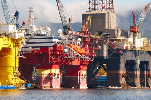
Petroleum and natural gas industries - Design and installation of piping systems on offshore production platforms (ISO 13703:2000)

Recommends minimum requirements and gives guidance for the design and installation of new piping systems on production platforms located offshore for the petroleum and natural gas industries. It covers piping systems up to 690 bar g maximum within a temperature range of -29°C to 343°C.

Erdöl- und Erdgasindustrien - Auslegung und Verlegung von Rohrleitungssystemen auf Offshore-Förderplattformen (ISO 13703:2000)

Diese Internationale Norm legt Mindestanforderungen fest und enthält einen Leitfaden für die Auslegung und Verlegung von neuen Rohrleitungssystemen auf Offshore-Förderplattformen für die Erdöl- und Erdgasindustrien. Die Norm gilt für Rohrleitungssysteme bis max. 60 000 kPa (ga) mit Temperaturgrenzwerten für die Werkstoffe in
Übereinstimmung mit den Anforderungen in ASME B 31.3.
ANMERKUNG   Für Anwendungsfälle außerhalb dieser Druck- und Temperaturbereiche kann diese Internationale Norm angewendet werden, jedoch sollte besonders auf die Werkstoffeigenschaften geachtet werden.
Anhang A enthält einige Lösungsbeispiele für Problemfälle bei der Auslegung von Rohrleitungen.

Industries du pétrole et du gaz naturel - Conception et installation de systemes de tuyauterie sur les plates-formes de production en mer (ISO 13703:2000)

La présente Norme internationale spécifie les exigences minimales et donne des lignes directrices pour la conception et l'installation de nouveaux systèmes de tuyauterie sur les plates-formes de production situées en mer, pour les industries du pétrole et du gaz naturel. Elle couvre les systèmes de tuyauterie supportant une pression maximale de 69 000 kPa, dans les limites d'une échelle de températures pour des matériaux répondant aux exigences de l'ASME B31.3.
L'annexe A donne quelques exemples pratiques pour résoudre des problèmes de conception de tuyauterie.

Petroleum and natural gas industries - Design and installation of piping systems on offshore production platforms (ISO 13703:2000)

General Information

Status
Published
Publication Date
31-May-2001
Current Stage
6060 - National Implementation/Publication (Adopted Project)
Start Date
01-Jun-2001
Due Date
01-Jun-2001
Completion Date
01-Jun-2001

Relations

Buy Standard

Standard
EN ISO 13703:2001
English language
80 pages
sale 10% off
Preview
sale 10% off
Preview
e-Library read for
1 day

Standards Content (Sample)

SLOVENSKI STANDARD
SIST EN ISO 13703:2001
01-junij-2001
Petroleum and natural gas industries - Design and installation of piping systems
on offshore production platforms (ISO 13703:2000)
Petroleum and natural gas industries - Design and installation of piping systems on
offshore production platforms (ISO 13703:2000)
Erdöl- und Erdgasindustrien - Auslegung und Verlegung von Rohrleitungssystemen auf
Offshore-Förderplattformen (ISO 13703:2000)
Industries du pétrole et du gaz naturel - Conception et installation de systemes de
tuyauterie sur les plates-formes de production en mer (ISO 13703:2000)
Ta slovenski standard je istoveten z: EN ISO 13703:2000
ICS:
75.180.10 Oprema za raziskovanje in Exploratory and extraction
odkopavanje equipment
SIST EN ISO 13703:2001 en
2003-01.Slovenski inštitut za standardizacijo. Razmnoževanje celote ali delov tega standarda ni dovoljeno.

---------------------- Page: 1 ----------------------

SIST EN ISO 13703:2001

---------------------- Page: 2 ----------------------

SIST EN ISO 13703:2001
EUROPEAN STANDARD
EN ISO 13703
NORME EUROPÉENNE
EUROPÄISCHE NORM
December 2000
ICS 75.180.10
English version
Petroleum and natural gas industries - Design and installation of
piping systems on offshore production platforms (ISO
13703:2000)
Industries du pétrole et du gaz naturel - Conception et Erdöl- und Erdgasindustrien - Auslegung und Verlegung
installation de systèmes de tuyauterie sur les plates-formes von Rohrleitungssystemen auf Offshore-Förderplattformen
de production en mer (ISO 13703:2000) (ISO 13703:2000)
This European Standard was approved by CEN on 9 December 2000.
CEN members are bound to comply with the CEN/CENELEC Internal Regulations which stipulate the conditions for giving this European
Standard the status of a national standard without any alteration. Up-to-date lists and bibliographical references concerning such national
standards may be obtained on application to the Management Centre or to any CEN member.
This European Standard exists in three official versions (English, French, German). A version in any other language made by translation
under the responsibility of a CEN member into its own language and notified to the Management Centre has the same status as the official
versions.
CEN members are the national standards bodies of Austria, Belgium, Czech Republic, Denmark, Finland, France, Germany, Greece,
Iceland, Ireland, Italy, Luxembourg, Netherlands, Norway, Portugal, Spain, Sweden, Switzerland and United Kingdom.
EUROPEAN COMMITTEE FOR STANDARDIZATION
COMITÉ EUROPÉEN DE NORMALISATION
EUROPÄISCHES KOMITEE FÜR NORMUNG
Management Centre: rue de Stassart, 36  B-1050 Brussels
© 2000 CEN All rights of exploitation in any form and by any means reserved Ref. No. EN ISO 13703:2000 E
worldwide for CEN national Members.

---------------------- Page: 3 ----------------------

SIST EN ISO 13703:2001
Page 2
EN ISO 13703:2000
CORRECTED  2002-07-24
Foreword
This document (ISO 13703:2000) has been prepared by Technical Committee ISO/TC 67
"Materials, equipment and offshore structures for petroleum and natural gas industries" in
collaboration with Technical Committee CEN/TC 12 "Materials, equipment and offshore
structures for petroleum and natural gas industries", the secretariat of which is held by AFNOR.
This European Standard shall be given the status of a national standard, either by publication of
an identical text or by endorsement, at the latest by June 2001, and conflicting national
standards shall be withdrawn at the latest by June 2001.
According to the CEN/CENELEC Internal Regulations, the national standards organizations of
the following countries are bound to implement this European Standard: Austria, Belgium, Czech
Republic, Denmark, Finland, France, Germany, Greece, Iceland, Ireland, Italy, Luxembourg,
Netherlands, Norway, Portugal, Spain, Sweden, Switzerland and the United Kingdom.
Endorsement notice
The text of the International Standard ISO 13703:2000 has been approved by CEN as a
European Standard without any modifications.

---------------------- Page: 4 ----------------------

SIST EN ISO 13703:2001

---------------------- Page: 5 ----------------------

SIST EN ISO 13703:2001
INTERNATIONAL ISO
STANDARD 13703
First edition
2000-12-15
Petroleum and natural gas industries —
Design and installation of piping systems
on offshore production platforms
Industries du pétrole et du gaz naturel — Conception et installation de
systèmes de tuyauterie sur les plates-formes de production en mer
Reference number
ISO 13703:2000(E)
©
ISO 2000

---------------------- Page: 6 ----------------------

SIST EN ISO 13703:2001
ISO 13703:2000(E)
PDF disclaimer
This PDF file may contain embedded typefaces. In accordance with Adobe's licensing policy, this file may be printed or viewed but shall not
be edited unless the typefaces which are embedded are licensed to and installed on the computer performing the editing. In downloading this
file, parties accept therein the responsibility of not infringing Adobe's licensing policy. The ISO Central Secretariat accepts no liability in this
area.
Adobe is a trademark of Adobe Systems Incorporated.
Details of the software products used to create this PDF file can be found in the General Info relative to the file; the PDF-creation parameters
were optimized for printing. Every care has been taken to ensure that the file is suitable for use by ISO member bodies. In the unlikely event
that a problem relating to it is found, please inform the Central Secretariat at the address given below.
© ISO 2000
All rights reserved. Unless otherwise specified, no part of this publication may be reproduced or utilized in any form or by any means, electronic
or mechanical, including photocopying and microfilm, without permission in writing from either ISO at the address below or ISO's member body
in the country of the requester.
ISO copyright office
Case postale 56 � CH-1211 Geneva 20
Tel. + 41 22 749 01 11
Fax + 41 22 749 09 47
E-mail copyright@iso.ch
Web www.iso.ch
Printed in Switzerland
ii © ISO 2000 – All rights reserved

---------------------- Page: 7 ----------------------

SIST EN ISO 13703:2001
ISO 13703:2000(E)
Contents Page
Foreword.v
Introduction.vi
1 Scope .1
2 Normative references .1
3 Terms, definitions, symbols and abbreviated terms.2
3.1 Terms and definitions .2
3.2 Symbols and abbreviated terms .4
4 General considerations.6
4.1 Materials .6
4.2 Code of pressure piping .7
4.3 Demarcation between systems with different pressure ratings.7
4.4 Corrosion considerations .9
5 Piping design .10
5.1 Pipe material grades.10
5.2 Sizing criteria — General .12
5.3 Sizing methods for liquid lines.12
5.4 Sizing criteria for single-phase gas lines.19
5.5 Sizing criteria for gas/liquid two-phase lines .23
5.6 Pipe wall thicknesses.26
5.7 Joint connections .30
5.8 Expansion and flexibility.31
5.9 Start-up provisions.32
6 Selection of valves .32
6.1 General.32
6.2 Types of valves .33
6.3 Fire resistance of valves .35
6.4 Valve sizing .35
6.5 Valve pressure and temperature ratings.36
6.6 Valve materials.37
7 Fittings and flanges.37
7.1 General.37
7.2 Welded fittings .38
7.3 Screwed fittings .38
7.4 Branch connections .38
7.5 Flanges .39
7.6 Proprietary connectors .41
7.7 Special requirements for sulfide stress-cracking service.41
7.8 Erosion prevention .41
8 Design considerations for particular piping systems.41
8.1 General.41
8.2 Wellhead accessory items .41
8.3 Flowline and flowline accessories.42
8.4 Production manifolds.45
8.5 Process vessel piping .45
8.6 Utility systems.47
8.7 Heating fluid and glycol systems.48
8.8 Pressure relief and disposal systems .48
8.9 Drain systems .50
© ISO 2000 – All rights reserved iii

---------------------- Page: 8 ----------------------

SIST EN ISO 13703:2001
ISO 13703:2000(E)
8.10 Bridge piping between platforms.50
8.11 Risers .50
8.12 Sampling valves.51
9 Considerations of related items .51
9.1 General.51
9.2 Layout .51
9.3 Elevations .51
9.4 Piping supports.51
9.5 Other corrosion considerations .51
9.6 Thermal insulation .54
9.7 Noise .56
9.8 Pipe, valves and fittings tables.56
9.9 Inspection, maintenance, repair and modification.56
10 Installation and quality control.56
10.1 General.56
10.2 Welding .56
10.3 Pressure testing.57
10.4 Test record.58
Annex A (informative) Example problems .59
Annex B (informative) Examples of pipe, valves and fittings tables.71
Annex C (informative) Acceptable butt-welded joint design for unequal wall thicknesses .74
Bibliography .76
iv © ISO 2000 – All rights reserved

---------------------- Page: 9 ----------------------

SIST EN ISO 13703:2001
ISO 13703:2000(E)
Foreword
ISO (the International Organization for Standardization) is a worldwide federation of national standards bodies (ISO
member bodies). The work of preparing International Standards is normally carried out through ISO technical
committees. Each member body interested in a subject for which a technical committee has been established has
the right to be represented on that committee. International organizations, governmental and non-governmental, in
liaison with ISO, also take part in the work. ISO collaborates closely with the International Electrotechnical
Commission (IEC) on all matters of electrotechnical standardization.
International Standards are drafted in accordance with the rules given in the ISO/IEC Directives, Part 3.
Draft International Standards adopted by the technical committees are circulated to the member bodies for voting.
Publication as an International Standard requires approval by at least 75 % of the member bodies casting a vote.
Attention is drawn to the possibility that some of the elements of this International Standard may be the subject of
patent rights. ISO shall not be held responsible for identifying any or all such patent rights.
International Standard ISO 13703 was prepared by Technical Committee ISO/TC 67, Materials, equipment and
offshore structures for petroleum and natural gas industries, Subcommittee SC 6, Processing equipment and
systems.
Annexes A, B and C of this International Standard are for information only.
© ISO 2000 – All rights reserved v

---------------------- Page: 10 ----------------------

SIST EN ISO 13703:2001
ISO 13703:2000(E)
Introduction
th
This International Standard is based on API RP 14E, 5 edition, October 1991.
vi © ISO 2000 – All rights reserved

---------------------- Page: 11 ----------------------

SIST EN ISO 13703:2001
INTERNATIONAL STANDARD ISO 13703:2000(E)
Petroleum and natural gas industries — Design and installation of
piping systems on offshore production platforms
1 Scope
This International Standard specifies minimum requirements and gives guidance for the design and installation of
new piping systems on production platforms located offshore for the petroleum and natural gas industries. It covers
piping systems up to 69 000 kPa (ga) maximum, within temperature range limits for the materials meeting the
requirements of ASME B31.3.
NOTE For applications outside these pressure and temperature ranges, this International Standard may be used but
special consideration should be given to material properties.
Annex A gives some worked examples for solving piping design problems.
2 Normative references
The following normative documents contain provisions which, through reference in this text, constitute provisions of
this International Standard. For dated references, subsequent amendments to, or revisions of, any of these
publications do not apply. However, parties to agreements based on this International Standard are encouraged to
investigate the possibility of applying the most recent editions of the normative documents indicated below. For
undated references, the latest edition of the normative document referred to applies. Members of ISO and IEC
maintain registers of currently valid International Standards.
ISO 13623, Petroleum and natural gas industries — Pipeline transportation systems.
1)
API RP 520-2 , Recommended practice for design and installation of pressure-relieving systems in refineries —
Part 2.
2)
ASME , Boiler and pressure vessel code: Section VIII: Pressure vessels, Division 1.
ASME B 31.3, Process piping.
3)
NACE MR0175 , Sulfide stress cracking resistant metallic materials for oil field equipment.
NACE TM0177, Laboratory testing of metals for resistance to specific forms of environmental cracking in H S
2
environments.
NACE TM0284, Evaluation of pipeline and pressure vessel steels for resistance to hydrogen-induced cracking.
1) American Petroleum Institute, 1220 L Street, N.W., Washington, DC 20005-4070, U.S.A.
th
2) American Society of Mechanical Engineers, 345 East 47 Street, New York, N.Y. 10017, U.S.A.
3) National Association of Corrosion Engineers, P.O. Box 218340, Houston, Texas 77218-8340, U.S.A.
© ISO 2000 – All rights reserved 1

---------------------- Page: 12 ----------------------

SIST EN ISO 13703:2001
ISO 13703:2000(E)
3 Terms, definitions, symbols and abbreviated terms
For the purposes of this International Standard, the following terms, definitions, symbols and abbreviated terms
apply.
3.1 Terms and definitions
3.1.1
chloride stress-corrosion cracking service
service in which the process stream contains water and chlorides in a sufficient concentration, and at a high
enough temperature, to induce stress-corrosion cracking of susceptible materials
NOTE Other constituents present, such as oxygen (O ), may contribute to such chloride stress-corrosion cracking.
2
3.1.2
choke
device specifically intended to restrict the flow rate of fluids
3.1.3
corrosion-erosion
eroding away of a protective film of corrosion product by the action of the process stream, exposing fresh metal
which then corrodes
NOTE Extremely high metal mass loss can occur under these conditions.
3.1.4
corrosive gas
gas which, when dissolved in water or other liquid, causes corrosion of metal
NOTE Corrosive gases usually contain hydrogen sulfide (H S), carbon dioxide (CO ) and/or oxygen (O ).
2 2 2
3.1.5
corrosive hydrocarbon service
service in which the process stream contains water or brine and carbon dioxide (CO ), hydrogen sulfide (H S),
2 2
oxygen (O ) or other corrosive agents under conditions which cause corrosion of metal
2
3.1.6
expansion bellows
corrugated piping device designed to absorb expansion and contraction
3.1.7
expansion bend
piping configuration designed to absorb expansion and contraction
3.1.8
flowline
piping that carries well fluid from wellhead to manifold or first process vessel
3.1.9
flow regime
flow condition of a multi-phase process stream
EXAMPLES Slug flow, mist flow or stratified flow.
3.1.10
fluid
gas, vapour, liquid or combinations thereof
2 © ISO 2000 – All rights reserved

---------------------- Page: 13 ----------------------

SIST EN ISO 13703:2001
ISO 13703:2000(E)
3.1.11
header
part of a manifold that directs fluid to a specific process system
See Figures 5 and 6.
3.1.12
hydrocarbon wettability
ability of the process stream to form a protective hydrocarbon film on metal surfaces
3.1.13
manifold
assembly of pipe, valves and fittings by which fluid from one or more sources is selectively directed to various
process systems
3.1.14
nipple
section of threaded or socket-welded pipe, shorter than 300 mm, used as an appurtenance
3.1.15
nominal pipe size
nominal size
NPS
DN
designation of size in inches which is common to all components in a piping system other than those components
designated by outside diameter
NOTE Nominal pipe size is designated by the letters NPS (when relating to inches) or DN (when relating to millimetres)
followed by a number; it is a convenient number for reference purposes and it is normally only loosely related to manufacturing
dimensions.
3.1.16
non-corrosive hydrocarbon service
service in which the process stream conditions do not cause significant metal mass loss, selective attack, chloride
stress-corrosion cracking or sulfide stress-cracking
3.1.17
normal conditions
absolute pressure of 101,325 kPa and temperature of 0 °C
3.1.18
platform piping
any piping intended to contain or transport fluid on a platform
3.1.19
pressure rating
number relating to the pressure for which a system is suitable
NOTE The number may relate directly to the rated working pressure (e.g. ISO 10423 [1] pressure rating 13,8 MPa and API
pressure rating 2 000 psi) or may have a more indirect correlation (e.g. ASME class 300).
3.1.20
pressure sensor
device designed to detect a predetermined pressure
3.1.21
process component
single functional piece of production equipment and associated piping
EXAMPLES Pressure vessel, heater, pump, etc.
© ISO 2000 – All rights reserved 3

---------------------- Page: 14 ----------------------

SIST EN ISO 13703:2001
ISO 13703:2000(E)
3.1.22
riser
vertical portion of a pipeline (including the bottom bend) arriving on or departing from a platform
3.1.23
shutdown valve
automatically-operated valve used for isolating a process component or process system
3.1.24
sulfide stress-cracking service
service in which the process stream contains water or brine and contains a sufficient concentration of hydrogen
sulfide (H S) to induce sulfide stress-cracking of susceptible materials
2
3.1.25
wellhead pressure
maximum shut-in surface pressure that may exist in a well
3.2 Symbols and abbreviated terms
3.2.1 Symbols
A minimum pipe cross-sectional flow area required per unit volume flowrate, expressed in square
2 3
millimetres per cubic metre per hour (mm /m /h)
B mean coefficient of thermal expansion at operating temperatures normally encountered, expressed in
millimetres per kelvin (mm/K)
C empirical constant, dimensionless
C sum of corrosion, mechanical strength and thread allowance, expressed in millimetres (mm)
e
C valve coefficient, dimensionless
v
NOTE 1 This value is equal to the water flowrate in US gpm at 60 °F required to generate a pressure drop of 1 psi
(US Customary units only are used in this instance to maintain alignment with other published data).
D pipe inside diameter, expressed in metres (m)
i
D pipe outside diameter, expressed in millimetres (mm)
o
d pipe inside diameter, expressed in millimetres (mm)
i
d gas relative density (air = 1), dimensionless
g
d liquid relative density (water = 1), dimensionless
L
E longitudinal weld joint factor, dimensionless
E modulus of elasticity of piping material in the cold condition, expressed in newtons per square millimetre
m
2
(N/mm )
f Moody friction factor, dimensionless
2
g gravitational constant, expressed in metres per second per second (m/s )
h acceleration head, expressed in metres (m) of liquid
a
h friction head, expressed in metres (m) of liquid
f
4 © ISO 2000 – All rights reserved

---------------------- Page: 15 ----------------------

SIST EN ISO 13703:2001
ISO 13703:2000(E)
h absolute pressure head, expressed in metres (m) of liquid
p
h static head, expressed in metres (m) of liquid
st
h velocity head, expressed in metres (m) of liquid
vh
h absolute vapour pressure, expressed in metres (m) of liquid
vpa
h pressure loss, expressed in kilopascals (kPa)
W
K acceleration factor, dimensionless
L developed pipe length, expressed in metres (m)
L pipe length, expressed in kilometres (km)
m
m manufacturing wall thickness tolerance, expressed as a percentage (%)
NPSH available net positive suction head, expressed in metres (m) of liquid
a
p operating pressure, expressed in kilopascals [kPa (abs)]
NOTE 2 Also denoted in text as “flowing pressure”.
p internal design pressure, expressed in kilopascals [kPa (ga)]
i
3
q gas flow rate, expressed in cubic metres per hour (m /h) at normal conditions
g
3
q liquid flow rate, expressed in cubic metres per hour (m /h)
L
q total liquid plus vapour mass flowrate, expressed in kilograms per hour (kg/h)
m
R gas/liquid volume ratio, dimensionless
Re Reynolds number, dimensionless
R pump speed, expressed in revolutions per minute (r/min)
p
2
S allowable stress, expressed in newtons per square millimetre (N/mm )
T operating temperature, expressed in kelvin (K)
NOTE 3 Also denoted in text as “flowing temperature”.
t pressure design thickness, expressed in millimetres (mm)
t minimum nominal pipe wall thickness, expressed in millimetres (mm)
nom
U anchor distance (straight line distance between anchors), expressed in metres (m)
v fluid erosional velocity, expressed in metres per second (m/s)
e
v average gas velocity, expressed in metres per second (m/s)
g
NOTE 4 Also denoted in text as “gas velocity”
v average liquid velocity, expressed in metres per second (m/s)
L
y resultant of total displacement strains, expressed in millimetres (mm)
© ISO 2000 – All rights reserved 5

---------------------- Page: 16 ----------------------

SIST EN ISO 13703:2001
ISO 13703:2000(E)
Y temperature factor, dimensionless
Z gas compressibility factor, dimensionless
�L expansion to be absorbed by pipe, expressed in millimetres (mm)
�p pressure drop, expressed in kilopascals (kPa)
3
� gas density at operating pressure and temperature, expressed in kilograms per cubic metre (kg/m )
g
3
� liquid density at operating temperatu
...

Questions, Comments and Discussion

Ask us and Technical Secretary will try to provide an answer. You can facilitate discussion about the standard in here.