

SIST EN 301 406-1 V3.2.1:2026
(Main)Digital Enhanced Cordless Telecommunications (DECT) - Harmonised Standard for access to radio spectrum - Part 1: DECT, DECT Evolution and DECT ULE
- Abstract
The present document specifies technical characteristics and methods of measurements for equipment implementing the Digital Enhanced Cordless Telecommunications (DECT) common interface, as specified in the multi-part technical specification ETSI EN 300 175 including the variants DECT Evolution and DECT ULE (see ETSI EN 300 175-1 [i.3] for an overview). The present document applies to the following equipment types:
a) Fixed Part (FP);
b) Portable Part (PP);
c) Cordless Terminal Adapter (CTA);
d) Wireless Relay Station (WRS) (FP and PP combined);
e) Hybrid Part (HyP) (a PP with capability to act as a FP to provide PP to PP communication).
NOTE: This release of the standard covers the WRS type CRFP, but not the WRS type REP.
The DECT service frequency band for transmitting and receiving for all elements is 1 880 MHz to 1 900 MHz. National regulation can allow additional frequency bands. DECT equipment covered by the present document is operated in accordance with ERC Decision (98)22 [i.20]. Details of the DECT Common Interface may be found in the multi-part deliverable ETSI EN 300 175 (see [1] to [4] and [i.3] to [i.6]). Further details of the DECT system may be found in the ETSI TR 101 178 [i.1]. DECT ULE implements, in addition to the DECT Common Interface, the multi-part ETSI TS 102 939 (see ETSI TS 102 939-1 [i.7] and ETSI TS 102 939-2 [i.8]). The present document contains requirements to demonstrate that radio equipment both effectively uses and supports the efficient use of radio spectrum in order to avoid harmful interference. NOTE: The relationship between the present document and essential requirements of article 3.2 of Directive 2014/53/EU [i.10] is given in annex A.
- Status
- Published
- Public Enquiry End Date
- 31-Mar-2026
- Publication Date
- 20-Aug-2026
- Technical Committee
- MOC - Mobile Communications
- Current Stage
- 6060 - National Implementation/Publication (Adopted Project)
- Start Date
- 10-Aug-2026
- Due Date
- 15-Oct-2026
- Completion Date
- 21-Aug-2026
Buy Documents
ETSI EN 301 406-1 V3.2.0 (2026-01) - Digital Enhanced Cordless Telecommunications (DECT); Harmonised Standard for access to radio spectrum; Part 1: DECT, DECT Evolution and DECT ULE
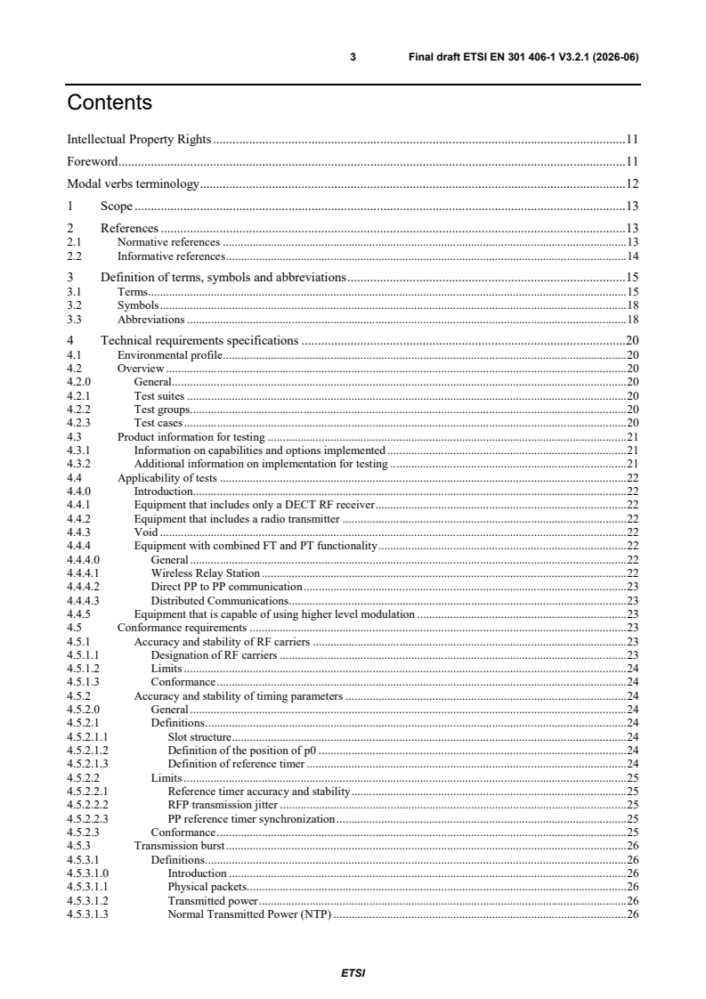
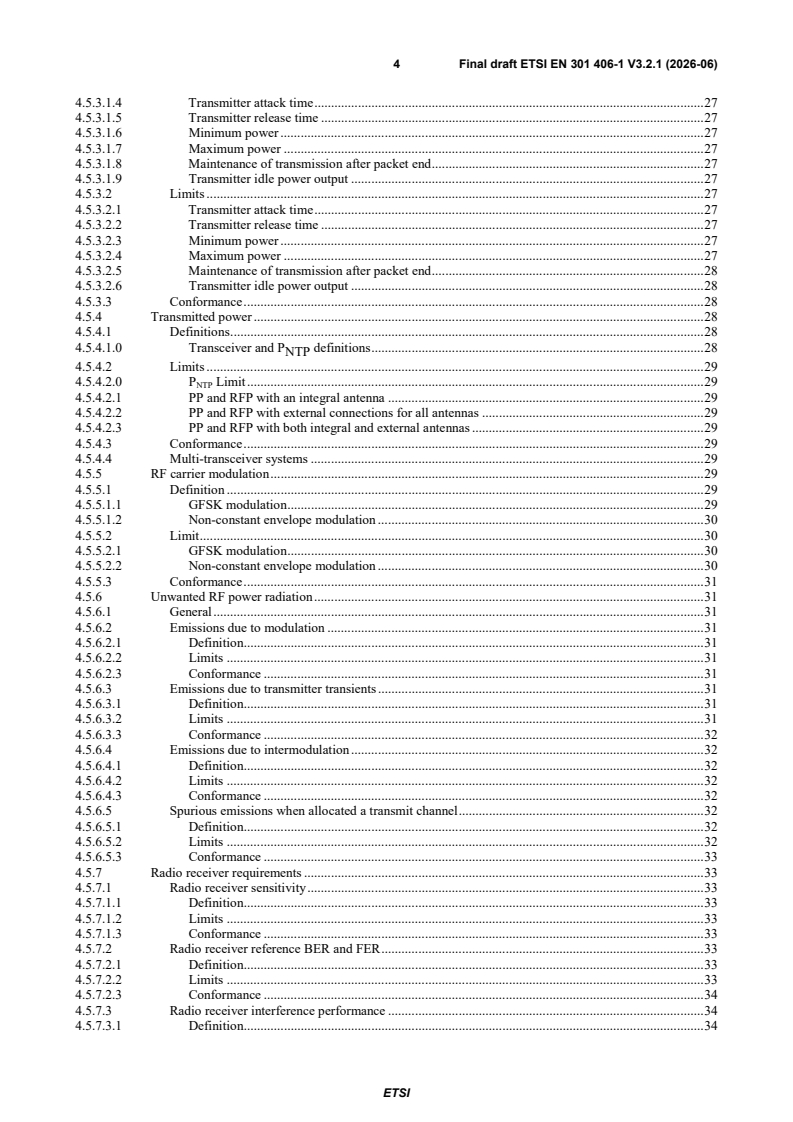
ETSI EN 301 406-1 V3.2.1 (2026-06) - Digital Enhanced Cordless Telecommunications (DECT); Harmonised Standard for access to radio spectrum; Part 1: DECT, DECT Evolution and DECT ULE

SIST EN 301 406-1 V3.2.1:2026 is the Slovenian adoption of ETSI EN 301 406-1, a harmonised European standard for DECT radio spectrum access. It specifies technical characteristics and measurement methods for DECT, DECT Evolution and DECT ULE equipment so manufacturers, test laboratories and conformity assessors can verify spectrum use, transmitter and receiver performance, and the radio tests linked to article 3.2 of Directive 2014/53/EU.
What does SIST EN 301 406-1 V3.2.1:2026 specify?
SIST EN 301 406-1 V3.2.1:2026 specifies the radio characteristics and conformance measurement methods for equipment implementing the DECT Common Interface. It applies to the main DECT equipment types used in fixed, portable, relay and hybrid roles, and it is written as a harmonised standard for access to radio spectrum.
The scope covers:
- Fixed Part (FP)
- Portable Part (PP)
- Cordless Terminal Adapter (CTA)
- Wireless Relay Station (WRS)
- Hybrid Part (HyP)
The document states that this release covers the WRS type CRFP, but not the WRS type REP. It also places DECT operation in the 1 880 MHz to 1 900 MHz service band, while allowing that national regulation can open additional bands.
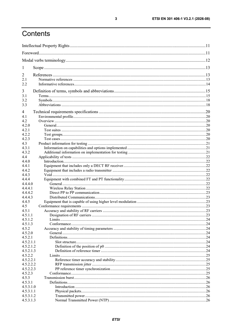
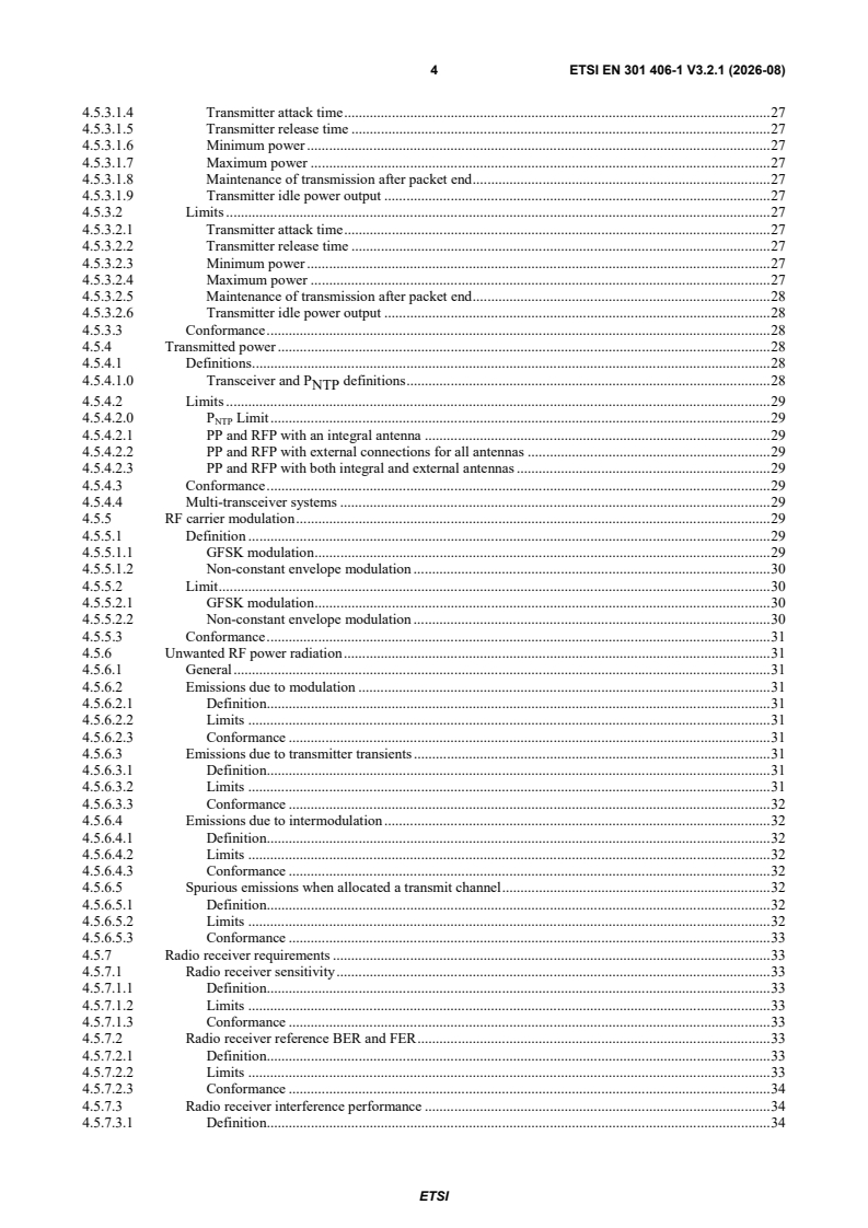
The standard is organised in five main clauses and a set of annexes:
- Clause 1 gives the scope.
- Clause 2 lists normative and informative references.
- Clause 3 defines terms, symbols and abbreviations.
- Clause 4 sets the technical requirements.
- Clause 5 gives the tests for compliance.
| Annex | What it covers |
|---|---|
| Annex A | Relationship with the essential requirements of Directive 2014/53/EU |
| Annex B | Maximum measurement uncertainty |
| Annex C | Test sites and arrangements for radiated measurements |
| Annex D | Procedures for radiated measurements |
| Annex E | Conducted spurious emissions |
| Annex F | Measurement of BER and FER |
| Annex G | Synchronization loss procedures for the LT |
| Annex H | Checklist against Directive 2014/53/EU technical parameters |
| Annex I | Bibliography |
| Annex J | Change history |
What are the key requirements of SIST EN 301 406-1 V3.2.1:2026?
Operating conditions and test setup
SIST EN 301 406-1 V3.2.1:2026 requires compliance across the intended operational environmental profile, with test conditions covering at least the environmental limits stated in the document. In practice, that means the equipment has to meet the radio requirements not just at one laboratory setting, but across the temperatures and supply conditions relevant to its use.
Clause 5 explains the test philosophy around a Lower Tester (LT) and an Upper Tester (UT). The LT emulates DECT FT and PT behaviour and controls the EUT through the air interface, while the UT inside the EUT responds to test commands. This matters because many measurements depend on placing the device into a defined test mode, not on normal user operation.
Frequency, timing and burst behaviour
Clause 4.5.1 covers RF carrier accuracy and stability, and clause 4.5.2 covers timing accuracy and slot-to-slot jitter. These are the core “stay on channel and stay on time” checks. For a buyer or engineer, they show whether a product can keep its DECT transmissions aligned closely enough to avoid disturbing other users of the band.
Clause 4.5.3 defines the transmission burst requirements, including attack time, release time, minimum and maximum power, transmission after packet end, and transmitter idle output. This matters because a compliant transmitter must start and stop cleanly around each packet, without excessive overshoot or residual output that can create interference.
Clause 4.5.4 covers transmitted power, with separate treatment for equipment using an integral antenna, an external antenna connector, or both. The clause also addresses multi-transceiver systems and how power is combined for assessment. In practice, this tells the test lab how to measure output power on real hardware, including products with antenna diversity or multiple ports.
Modulation and unwanted emissions
Clause 4.5.5 covers RF carrier modulation. For GFSK, the document uses peak frequency deviation as the key modulation measure. For non-constant envelope modulation, the document uses Error Vector Magnitude (EVM), which is the practical way to check whether higher level modulation is being generated cleanly enough for the air interface to work as intended.
Clause 4.5.6 deals with unwanted RF power radiation, including emissions due to modulation, transmitter transients, intermodulation and spurious emissions when a transmit channel is allocated. This is important because a DECT product can be technically functional but still fail if it radiates too much energy outside its intended channel or band.
Receiver performance
Clause 4.5.7 defines receiver sensitivity, reference Bit Error Ratio (BER) and Frame Error Ratio (FER), interference performance, blocking, receiver intermodulation, and spurious emissions when the PP has no allocated transmit channel. These requirements show how well the receiver survives weak signals and interfering signals while still recovering valid DECT traffic.
Clause 5.3.7 turns those receiver requirements into measurement methods, and Annex F gives the BER and FER measurement method. Annex G gives a procedure for handling synchronization loss in the LT. In practice, these parts tell a test laboratory how to judge whether a receiver is robust enough under realistic interference conditions.
Channel access and special DECT functions
Clause 4.5.8 covers channel access, including channel selection, confirmation and release, with extra treatment for DECT ULE. This is the part that shows whether the equipment can find, confirm and leave channels correctly.
Clause 4.5.9 covers WRS operation, including the CRFP frame multiplexing structure and buffering of relayed logical channels. Clause 4.5.10 covers Direct PP to PP communication, and clause 4.5.11 covers Distributed communications. Clause 4.5.12 covers higher level modulation options and their activation in Test Standby Mode (TSM). For a product that claims any of these functions, the standard tells the tester exactly which extra conformance path applies.
What terms does SIST EN 301 406-1 V3.2.1:2026 define?
- Fixed Part (DECT Fixed Part (FP)) - the network-side part of the DECT system between the local network and the DECT air interface.
- Portable Part (DECT Portable part (PP)) - the user-side part of the DECT system between the user and the DECT air interface.
- Wireless Relay Station (WRS) - a particular type of repeater defined by ETSI EN 300 700.
- Lower Tester (LT) - the test equipment, together with DECT-like PT/FT functions and a test controller, that drives the EUT during conformance testing.
- Upper Tester (UT) - the control function inside the EUT that receives test commands from the LT.
- Test Standby Mode (TSM) - the EUT mode used as the base test mode so that MAC test commands can be received and executed.
- non-constant envelope modulation - higher level modulation such as π/2-DBPSK, π/4-DQPSK, π/8-D8PSK, 16-QAM and 64-QAM, which is assessed by EVM.
- Bit Error Ratio (BER) / Frame Error Ratio (FER) - the error measures used to judge receiver performance and synchronization behaviour.
Who uses SIST EN 301 406-1 V3.2.1:2026?
SIST EN 301 406-1 V3.2.1:2026 is used by DECT equipment manufacturers, radio test laboratories, conformity assessment teams and regulatory compliance engineers. It is also relevant to quality managers and buyers who need to check whether a DECT product claim - for example FP, PP, CTA, WRS, HyP or DECT ULE functionality - is backed by the correct radio test approach.
In practice, users apply the standard when they:
- prepare product information for testing
- decide whether to use conducted or radiated measurements
- configure LT and UT test modes
- choose OATS, SAR or FAR test sites
- record measurement uncertainty in reports
- demonstrate conformity with the harmonised requirements linked to Directive 2014/53/EU
Which standards are used with SIST EN 301 406-1 V3.2.1:2026?
| Reference | What it contributes |
|---|---|
| ETSI EN 300 175-2 | Physical layer rules for DECT, including the radio behaviour used in modulation and timing tests |
| ETSI EN 300 175-3 | Medium Access Control (MAC) layer rules, including frame structure, bearer behaviour and test-command handling |
| ETSI EN 300 175-5 | Network layer background for DECT operation |
| ETSI EN 300 175-6 | Identities and addressing used by DECT equipment |
| ETSI EN 300 700 | Definition of the Wireless Relay Station (WRS) |
| Recommendation ITU-T O.153 | Basic parameters for measuring error performance below the primary rate |
| ETSI EN 300 175-1 | Overview of the DECT Common Interface |
| ETSI EN 300 175-4 | Data Link Control (DLC) layer |
| ETSI EN 300 175-7 | Security features |
| ETSI EN 300 175-8 | Speech and audio coding and transmission |
| ETSI TS 102 939-1 and ETSI TS 102 939-2 | DECT ULE functions for home automation and machine-to-machine communication |
| ETSI EN 300 176-1 | DECT radio test specification referenced for test background |
| ETSI EG 203 336 | Guidance for selecting technical parameters for harmonised standards |
| ETSI TR 100 028-1 and ETSI TR 100 028-2 | Measurement uncertainty guidance |
| ETSI TR 102 273-2, ETSI TR 102 273-3 and ETSI TR 102 273-4 | Radiated test site verification and uncertainty guidance |
What does the SIST EN 301 406-1 V3.2.1:2026 document contain?
The document contains a full set of radio conformance test cases in clause 4 and detailed measurement methods in clause 5. The test cases cover frequency stability, timing, transmission burst behaviour, power, modulation, unwanted emissions, receiver sensitivity and interference behaviour, channel access, WRS behaviour, Direct PP to PP communication, Distributed communications and higher level modulation.
It also contains test arrangements and figures for LT/UT setups, antenna use, loopback measurement, packet timing, and channel access scenarios. Annex C and Annex D describe the radiated test sites and the procedures for OATS, SAR and FAR measurements, including substitution measurements.
Annex F provides the BER and FER measurement method, and Annex G gives a practical procedure for synchronization loss during testing. Annex B gives recommended measurement uncertainty values, so test reports can show how the measured values were judged against the limits.
Annex H provides a checklist against the article 3.2 technical parameters of Directive 2014/53/EU, while Annex J records the change history.
Buy Documents
ETSI EN 301 406-1 V3.2.0 (2026-01) - Digital Enhanced Cordless Telecommunications (DECT); Harmonised Standard for access to radio spectrum; Part 1: DECT, DECT Evolution and DECT ULE
ETSI EN 301 406-1 V3.2.1 (2026-06) - Digital Enhanced Cordless Telecommunications (DECT); Harmonised Standard for access to radio spectrum; Part 1: DECT, DECT Evolution and DECT ULE
Get Certified
Connect with accredited certification bodies for this standard

ANCE
Mexican certification and testing association.

Intertek Slovenia
Intertek testing, inspection, and certification services in Slovenia.

LNE (Laboratoire National de Métrologie et d'Essais)
French national laboratory for metrology and testing.
Sponsored listings
Frequently Asked Questions
SIST EN 301 406-1 V3.2.1:2026 is a standard published by the Slovenian Institute for Standardization (SIST). Its full title is "Digital Enhanced Cordless Telecommunications (DECT) - Harmonised Standard for access to radio spectrum - Part 1: DECT, DECT Evolution and DECT ULE". This standard covers: The present document specifies technical characteristics and methods of measurements for equipment implementing the Digital Enhanced Cordless Telecommunications (DECT) common interface, as specified in the multi-part technical specification ETSI EN 300 175 including the variants DECT Evolution and DECT ULE (see ETSI EN 300 175-1 [i.3] for an overview). The present document applies to the following equipment types: a) Fixed Part (FP); b) Portable Part (PP); c) Cordless Terminal Adapter (CTA); d) Wireless Relay Station (WRS) (FP and PP combined); e) Hybrid Part (HyP) (a PP with capability to act as a FP to provide PP to PP communication). NOTE: This release of the standard covers the WRS type CRFP, but not the WRS type REP. The DECT service frequency band for transmitting and receiving for all elements is 1 880 MHz to 1 900 MHz. National regulation can allow additional frequency bands. DECT equipment covered by the present document is operated in accordance with ERC Decision (98)22 [i.20]. Details of the DECT Common Interface may be found in the multi-part deliverable ETSI EN 300 175 (see [1] to [4] and [i.3] to [i.6]). Further details of the DECT system may be found in the ETSI TR 101 178 [i.1]. DECT ULE implements, in addition to the DECT Common Interface, the multi-part ETSI TS 102 939 (see ETSI TS 102 939-1 [i.7] and ETSI TS 102 939-2 [i.8]). The present document contains requirements to demonstrate that radio equipment both effectively uses and supports the efficient use of radio spectrum in order to avoid harmful interference. NOTE: The relationship between the present document and essential requirements of article 3.2 of Directive 2014/53/EU [i.10] is given in annex A.
The present document specifies technical characteristics and methods of measurements for equipment implementing the Digital Enhanced Cordless Telecommunications (DECT) common interface, as specified in the multi-part technical specification ETSI EN 300 175 including the variants DECT Evolution and DECT ULE (see ETSI EN 300 175-1 [i.3] for an overview). The present document applies to the following equipment types: a) Fixed Part (FP); b) Portable Part (PP); c) Cordless Terminal Adapter (CTA); d) Wireless Relay Station (WRS) (FP and PP combined); e) Hybrid Part (HyP) (a PP with capability to act as a FP to provide PP to PP communication). NOTE: This release of the standard covers the WRS type CRFP, but not the WRS type REP. The DECT service frequency band for transmitting and receiving for all elements is 1 880 MHz to 1 900 MHz. National regulation can allow additional frequency bands. DECT equipment covered by the present document is operated in accordance with ERC Decision (98)22 [i.20]. Details of the DECT Common Interface may be found in the multi-part deliverable ETSI EN 300 175 (see [1] to [4] and [i.3] to [i.6]). Further details of the DECT system may be found in the ETSI TR 101 178 [i.1]. DECT ULE implements, in addition to the DECT Common Interface, the multi-part ETSI TS 102 939 (see ETSI TS 102 939-1 [i.7] and ETSI TS 102 939-2 [i.8]). The present document contains requirements to demonstrate that radio equipment both effectively uses and supports the efficient use of radio spectrum in order to avoid harmful interference. NOTE: The relationship between the present document and essential requirements of article 3.2 of Directive 2014/53/EU [i.10] is given in annex A.
SIST EN 301 406-1 V3.2.1:2026 is classified under the following ICS (International Classification for Standards) categories: 33.070.30 - Digital Enhanced Cordless Telecommunications (DECT). The ICS classification helps identify the subject area and facilitates finding related standards.
SIST EN 301 406-1 V3.2.1:2026 is available in PDF format for immediate download after purchase. The document can be added to your cart and obtained through the secure checkout process. Digital delivery ensures instant access to the complete standard document.
Standards Content (Sample)
ETSI EN 301 406-1 V3.2.0 (2026-01)
HARMONISED EUROPEAN STANDARD
Digital Enhanced Cordless Telecommunications (DECT);
Harmonised Standard for access to radio spectrum;
Part 1: DECT, DECT Evolution and DECT ULE
2 ETSI EN 301 406-1 V3.2.0 (2026-01)
Reference
REN/DECT-00411
Keywords
DECT, digital, generic, radio, regulation, testing
ETSI
650 Route des Lucioles
F-06921 Sophia Antipolis Cedex - FRANCE
Tel.: +33 4 92 94 42 00 Fax: +33 4 93 65 47 16
Siret N° 348 623 562 00017 - APE 7112B
Association à but non lucratif enregistrée à la
Sous-Préfecture de Grasse (06) N° w061004871
Important notice
The present document can be downloaded from the
ETSI Search & Browse Standards application.
The present document may be made available in electronic versions and/or in print. The content of any electronic and/or
print versions of the present document shall not be modified without the prior written authorization of ETSI. In case of any
existing or perceived difference in contents between such versions and/or in print, the prevailing version of an ETSI
deliverable is the one made publicly available in PDF format on ETSI deliver repository.
Users should be aware that the present document may be revised or have its status changed,
this information is available in the Milestones listing.
If you find errors in the present document, please send your comments to
the relevant service listed under Committee Support Staff.
If you find a security vulnerability in the present document, please report it through our
Coordinated Vulnerability Disclosure (CVD) program.
Notice of disclaimer & limitation of liability
The information provided in the present deliverable is directed solely to professionals who have the appropriate degree of
experience to understand and interpret its content in accordance with generally accepted engineering or
other professional standard and applicable regulations.
No recommendation as to products and services or vendors is made or should be implied.
In no event shall ETSI be held liable for loss of profits or any other incidental or consequential damages.
Any software contained in this deliverable is provided "AS IS" with no warranties, express or implied, including but not
limited to, the warranties of merchantability, fitness for a particular purpose and non-infringement of intellectual property
rights and ETSI shall not be held liable in any event for any damages whatsoever (including, without limitation, damages
for loss of profits, business interruption, loss of information, or any other pecuniary loss) arising out of or related to the use
of or inability to use the software.
Copyright Notification
No part may be reproduced or utilized in any form or by any means, electronic or mechanical, including photocopying and
microfilm except as authorized by written permission of ETSI.
The content of the PDF version shall not be modified without the written authorization of ETSI.
The copyright and the foregoing restriction extend to reproduction in all media.
© ETSI 2026.
All rights reserved.
ETSI
3 ETSI EN 301 406-1 V3.2.0 (2026-01)
Contents
Intellectual Property Rights . 11
Foreword . 11
Modal verbs terminology . 12
1 Scope . 13
2 References . 14
2.1 Normative references . 14
2.2 Informative references . 14
3 Definition of terms, symbols and abbreviations . 16
3.1 Terms . 16
3.2 Symbols . 19
3.3 Abbreviations . 19
4 Technical requirements specifications . 20
4.1 Environmental profile . 20
4.2 Overview . 20
4.2.0 General . 20
4.2.1 Test suites . 20
4.2.2 Test groups. 20
4.2.3 Test cases . 21
4.3 Product information for testing . 21
4.3.1 Information on capabilities and options implemented . 21
4.3.2 Additional information on implementation for testing . 22
4.4 Applicability of tests . 22
4.4.0 Introduction. 22
4.4.1 Equipment that includes only a DECT RF receiver . 22
4.4.2 Equipment that includes a radio transmitter . 22
4.4.3 Void . 22
4.4.4 Equipment with combined FT and PT functionality . 22
4.4.4.0 General . 22
4.4.4.1 Wireless Relay Station . 23
4.4.4.2 Direct PP to PP communication . 23
4.4.4.3 Distributed Communications. 23
4.4.5 Equipment that is capable of using higher level modulation . 23
4.5 Conformance requirements . 23
4.5.1 Accuracy and stability of RF carriers . 23
4.5.1.1 Designation of RF carriers . 23
4.5.1.2 Limits . 24
4.5.1.3 Conformance . 24
4.5.2 Accuracy and stability of timing parameters . 24
4.5.2.0 General . 24
4.5.2.1 Definitions . 24
4.5.2.1.1 Slot structure . 24
4.5.2.1.2 Definition of the position of p0 . 24
4.5.2.1.3 Definition of reference timer . 25
4.5.2.2 Limits . 25
4.5.2.2.1 Reference timer accuracy and stability . 25
4.5.2.2.2 RFP transmission jitter . 25
4.5.2.2.3 PP reference timer synchronization . 25
4.5.2.3 Conformance . 26
4.5.3 Transmission burst . 26
4.5.3.1 Definitions . 26
4.5.3.1.0 Introduction . 26
4.5.3.1.1 Physical packets. 26
4.5.3.1.2 Transmitted power . 26
4.5.3.1.3 Normal Transmitted Power (NTP) . 27
ETSI
4 ETSI EN 301 406-1 V3.2.0 (2026-01)
4.5.3.1.4 Transmitter attack time . 27
4.5.3.1.5 Transmitter release time . 27
4.5.3.1.6 Minimum power . 27
4.5.3.1.7 Maximum power . 27
4.5.3.1.8 Maintenance of transmission after packet end . 27
4.5.3.1.9 Transmitter idle power output . 27
4.5.3.2 Limits . 27
4.5.3.2.1 Transmitter attack time . 27
4.5.3.2.2 Transmitter release time . 27
4.5.3.2.3 Minimum power . 27
4.5.3.2.4 Maximum power . 27
4.5.3.2.5 Maintenance of transmission after packet end . 28
4.5.3.2.6 Transmitter idle power output . 28
4.5.3.3 Conformance . 28
4.5.4 Transmitted power . 28
4.5.4.1 Definitions . 28
4.5.4.1.0 Transceiver and P definitions . 28
NTP
4.5.4.2 Limits . 29
4.5.4.2.0 P Limit . 29
NTP
4.5.4.2.1 PP and RFP with an integral antenna . 29
4.5.4.2.2 PP and RFP with external connections for all antennas . 29
4.5.4.2.3 PP and RFP with both integral and external antennas . 29
4.5.4.3 Conformance . 29
4.5.4.4 Multi-transceiver systems . 29
4.5.5 RF carrier modulation . 29
4.5.5.1 Definition . 29
4.5.5.1.1 GFSK modulation . 29
4.5.5.1.2 Non-constant envelope modulation . 30
4.5.5.2 Limit . 30
4.5.5.2.1 GFSK modulation . 30
4.5.5.2.2 Non-constant envelope modulation . 30
4.5.5.3 Conformance . 31
4.5.6 Unwanted RF power radiation . 31
4.5.6.1 General . 31
4.5.6.2 Emissions due to modulation . 31
4.5.6.2.1 Definition. 31
4.5.6.2.2 Limits . 31
4.5.6.2.3 Conformance . 31
4.5.6.3 Emissions due to transmitter transients . 31
4.5.6.3.1 Definition. 31
4.5.6.3.2 Limits . 31
4.5.6.3.3 Conformance . 32
4.5.6.4 Emissions due to intermodulation . 32
4.5.6.4.1 Definition. 32
4.5.6.4.2 Limits . 32
4.5.6.4.3 Conformance . 32
4.5.6.5 Spurious emissions when allocated a transmit channel . 32
4.5.6.5.1 Definition. 32
4.5.6.5.2 Limits . 32
4.5.6.5.3 Conformance . 33
4.5.7 Radio receiver requirements . 33
4.5.7.1 Radio receiver sensitivity . 33
4.5.7.1.1 Definition. 33
4.5.7.1.2 Limits . 33
4.5.7.1.3 Conformance . 33
4.5.7.2 Radio receiver reference BER and FER . 33
4.5.7.2.1 Definition. 33
4.5.7.2.2 Limits . 33
4.5.7.2.3 Conformance . 34
4.5.7.3 Radio receiver interference performance . 34
4.5.7.3.1 Definition. 34
ETSI
5 ETSI EN 301 406-1 V3.2.0 (2026-01)
4.5.7.3.2 Limits . 34
4.5.7.3.3 Conformance . 34
4.5.7.4 Radio receiver blocking case 1: owing to signals occurring at the same time but on other
frequencies . 34
4.5.7.4.1 Definition. 34
4.5.7.4.2 Limits . 34
4.5.7.4.3 Conformance . 35
4.5.7.5 Radio receiver blocking case 2: owing to signals occurring at a different time . 35
4.5.7.5.1 Definition. 35
4.5.7.5.2 Limits . 35
4.5.7.5.3 Conformance . 35
4.5.7.6 Receiver intermodulation performance . 35
4.5.7.6.1 Definition. 35
4.5.7.6.2 Limits . 35
4.5.7.6.3 Conformance . 35
4.5.7.7 Spurious emissions when the PP has no allocated transmit channel . 35
4.5.7.7.1 Definition. 35
4.5.7.7.2 Limits . 35
4.5.7.7.3 Conformance . 36
4.5.8 Channel access . 36
4.5.8.1 Channel selection . 36
4.5.8.2 Channel confirmation . 36
4.5.8.2.1 For the PT . 36
4.5.8.2.2 For the FT . 36
4.5.8.3 Channel release . 37
4.5.8.4 General . 37
4.5.8.5 Channel selection and confirmation for DECT ULE . 37
4.5.8.5.1 General . 37
4.5.8.5.2 For the PT . 37
4.5.8.5.3 For the FT . 37
4.5.9 WRS. 37
4.5.9.0 General requirements . 37
4.5.9.1 PP operation . 38
4.5.9.2 RFP operation . 38
4.5.9.3 Additional requirements . 38
4.5.9.4 Conformance . 39
4.5.10 Direct PP to PP communication . 39
4.5.10.1 General requirements . 39
4.5.10.2 Conformance . 39
4.5.11 Distributed communications . 39
4.5.11.0 General requirements . 39
4.5.11.1 PP operation . 39
4.5.11.2 RFP operation . 39
4.5.11.3 Conformance . 40
4.5.12 Higher level modulation options . 40
4.5.12.0 Requirements . 40
4.5.12.1 Conformance . 40
5 Testing for compliance with technical requirements . 41
5.0 Environmental conditions for testing . 41
5.1 General test requirements . 41
5.1.1 Test philosophy . 41
5.1.1.1 General . 41
5.1.1.2 Lower Tester (LT) . 41
5.1.1.3 Non-signalling test mode . 42
5.1.1.4 Test environment . 43
5.1.1.4.1 General . 43
5.1.1.4.2 Conducted test . 43
5.1.1.4.3 Radiated test . 43
5.1.2 Test site . 43
5.1.2.1 Open air test site . 43
5.1.2.1.1 Description . 43
ETSI
6 ETSI EN 301 406-1 V3.2.0 (2026-01)
5.1.2.2 Anechoic chamber . 44
5.1.2.2.1 General . 44
5.1.3 Standard position . 44
5.1.4 Test antenna of the LT . 44
5.1.5 Substitution antenna . 44
5.1.6 Test fixture . 44
5.1.7 Equipment with a temporary or internal permanent antenna connector. 45
5.1.7.1 General . 45
5.1.7.2 Equipment with a temporary antenna connector . 45
5.1.8 Void . 45
5.1.9 Lower Tester (LT) . 45
5.1.9.1 Description . 45
5.1.9.2 Connections between the EUT and the LT . 46
5.1.9.3 Functions and abilities. 46
5.1.9.4 Signal generation uncertainty . 47
5.1.9.5 Modulated DECT-like carrier . 47
5.1.9.6 CW interferers . 47
5.1.9.7 DECT RF signal . 47
5.1.9.8 Test modulation signals . 47
5.1.10 Upper Tester (UT) . 47
5.1.10.1 Description of the UT. 47
5.1.10.2 The Test Standby Mode (TSM) . 48
5.1.10.3 Test messages . 48
5.1.10.4 Dummy setting when EUT is an RFP and is in Test Standby Mode (TSM) . 48
5.1.11 Description of the lower tester FT and PT . 48
5.1.12 General test methods . 49
5.1.12.1 General . 49
5.1.12.2 Sampling the RF signal . 49
5.1.12.2.1 Introduction . 49
5.1.12.2.2 Sampling method . 49
5.1.12.3 Determining the reference position . 49
5.1.12.3.0 General . 49
5.1.12.3.1 Case 1: EUTs that cannot transmit . 49
5.1.12.3.2 Case 2: EUTs that can transmit . 49
5.1.12.4 Bit Error Ratio (BER) and Frame Error Ratio (FER) measurements . 49
5.1.13 Test setup . 50
5.1.13.1 General . 50
5.1.13.2 Test setup 1 . 50
5.1.13.3 Test setup 2 . 50
5.1.13.4 Test setup 3 . 51
5.1.13.5 Test setup 4 . 51
5.1.14 Test arrangements for intermodulation measurements . 52
5.1.14.1 PT to PT arrangement . 52
5.1.14.2 FT to FT arrangement . 52
5.1.14.3 FT to PT arrangement . 53
5.1.15 Test conditions, power supply and ambient temperatures . 53
5.1.15.1 General . 53
5.1.15.2 Nominal test conditions . 53
5.1.15.3 Extreme test conditions . 54
5.1.15.4 Test power source - general requirements . 55
5.1.15.5 Nominal test power source . 55
5.1.15.5.1 Mains voltage . 55
5.1.15.5.2 Regulated lead acid battery power sources . 55
5.1.15.5.3 Nickel cadmium or nickel metal hydride battery . 55
5.1.15.5.4 Other power sources . 55
5.1.15.6 Extreme test power source . 55
5.1.15.6.1 Mains voltage . 55
5.1.15.6.2 Regulated lead acid battery power sources . 55
5.1.15.6.3 Nickel cadmium or nickel metal hydride battery . 55
5.1.15.6.4 Other power sources . 56
5.2 Interpretation of the measurement results . 56
5.3 Radio test suites . 56
ETSI
7 ETSI EN 301 406-1 V3.2.0 (2026-01)
5.3.1 Accuracy and stability of RF carriers . 56
5.3.1.1 Test environment . 56
5.3.1.2 Method of measurement . 56
5.3.1.3 Verdict criteria when the EUT is an RFP . 57
5.3.1.4 Verdict criteria when the EUT is a PP . 57
5.3.2 Accuracy and stability of timing parameters . 57
5.3.2.1 Measurement of packet timing jitter . 57
5.3.2.1.1 Test environment . 57
5.3.2.1.2 Method of measurement . 57
5.3.2.1.3 Verdict criteria . 58
5.3.2.2 Measurement of the reference timing accuracy of an RFP . 58
5.3.2.2.1 Test environment . 58
5.3.2.2.2 Method of measurement . 58
5.3.2.2.3 Verdict criteria . 58
5.3.2.3 Measurement of packet transmission accuracy of a PP . 59
5.3.2.3.1 Test environment . 59
5.3.2.3.2 Method of measurement . 59
5.3.2.3.3 Verdict criteria . 59
5.3.3 Transmission burst . 60
5.3.3.1 Test environment . 60
5.3.3.2 Method of measurement . 60
5.3.3.3 Verdict criteria . 60
5.3.4 Transmitted power . 61
5.3.4.1 PP and RFP with an integral antenna . 61
5.3.4.1.1 Test environment .
...
Final draft ETSI EN 301 406-1 V3.2.1 (2026-06)
HARMONISED EUROPEAN STANDARD
Digital Enhanced Cordless Telecommunications (DECT);
Harmonised Standard for access to radio spectrum;
Part 1: DECT, DECT Evolution and DECT ULE
2 Final draft ETSI EN 301 406-1 V3.2.1 (2026-06)
Reference
REN/DECT-00411
Keywords
DECT, digital, generic, radio, regulation, testing
ETSI
650 Route des Lucioles
F-06921 Sophia Antipolis Cedex - FRANCE
Tel.: +33 4 92 94 42 00 Fax: +33 4 93 65 47 16
Siret N° 348 623 562 00017 - APE 7112B
Association à but non lucratif enregistrée à la
Sous-Préfecture de Grasse (06) N° w061004871
Important notice
The present document can be downloaded from the
ETSI Search & Browse Standards application.
The present document may be made available in electronic versions and/or in print. The content of any electronic and/or
print versions of the present document shall not be modified without the prior written authorization of ETSI. In case of any
existing or perceived difference in contents between such versions and/or in print, the prevailing version of an ETSI
deliverable is the one made publicly available in PDF format on ETSI deliver repository.
Users should be aware that the present document may be revised or have its status changed,
this information is available in the Milestones listing.
If you find errors in the present document, please send your comments to
the relevant service listed under Committee Support Staff.
If you find a security vulnerability in the present document, please report it through our
Coordinated Vulnerability Disclosure (CVD) program.
Notice of disclaimer & limitation of liability
The information provided in the present deliverable is directed solely to professionals who have the appropriate degree of
experience to understand and interpret its content in accordance with generally accepted engineering or
other professional standard and applicable regulations.
No recommendation as to products and services or vendors is made or should be implied.
In no event shall ETSI be held liable for loss of profits or any other incidental or consequential damages.
Any software contained in this deliverable is provided "AS IS" with no warranties, express or implied, including but not
limited to, the warranties of merchantability, fitness for a particular purpose and non-infringement of intellectual property
rights and ETSI shall not be held liable in any event for any damages whatsoever (including, without limitation, damages
for loss of profits, business interruption, loss of information, or any other pecuniary loss) arising out of or related to the use
of or inability to use the software.
Copyright Notification
No part may be reproduced or utilized in any form or by any means, electronic or mechanical, including photocopying and
microfilm except as authorized by written permission of ETSI.
The content of the PDF version shall not be modified without the written authorization of ETSI.
The copyright and the foregoing restriction extend to reproduction in all media.
© ETSI 2026.
All rights reserved.
ETSI
3 Final draft ETSI EN 301 406-1 V3.2.1 (2026-06)
Contents
Intellectual Property Rights . 11
Foreword . 11
Modal verbs terminology . 12
1 Scope . 13
2 References . 13
2.1 Normative references . 13
2.2 Informative references . 14
3 Definition of terms, symbols and abbreviations . 15
3.1 Terms . 15
3.2 Symbols . 18
3.3 Abbreviations . 18
4 Technical requirements specifications . 20
4.1 Environmental profile . 20
4.2 Overview . 20
4.2.0 General . 20
4.2.1 Test suites . 20
4.2.2 Test groups. 20
4.2.3 Test cases . 20
4.3 Product information for testing . 21
4.3.1 Information on capabilities and options implemented . 21
4.3.2 Additional information on implementation for testing . 21
4.4 Applicability of tests . 22
4.4.0 Introduction. 22
4.4.1 Equipment that includes only a DECT RF receiver . 22
4.4.2 Equipment that includes a radio transmitter . 22
4.4.3 Void . 22
4.4.4 Equipment with combined FT and PT functionality . 22
4.4.4.0 General . 22
4.4.4.1 Wireless Relay Station . 22
4.4.4.2 Direct PP to PP communication . 23
4.4.4.3 Distributed Communications. 23
4.4.5 Equipment that is capable of using higher level modulation . 23
4.5 Conformance requirements . 23
4.5.1 Accuracy and stability of RF carriers . 23
4.5.1.1 Designation of RF carriers . 23
4.5.1.2 Limits . 24
4.5.1.3 Conformance . 24
4.5.2 Accuracy and stability of timing parameters . 24
4.5.2.0 General . 24
4.5.2.1 Definitions . 24
4.5.2.1.1 Slot structure . 24
4.5.2.1.2 Definition of the position of p0 . 24
4.5.2.1.3 Definition of reference timer . 24
4.5.2.2 Limits . 25
4.5.2.2.1 Reference timer accuracy and stability . 25
4.5.2.2.2 RFP transmission jitter . 25
4.5.2.2.3 PP reference timer synchronization . 25
4.5.2.3 Conformance . 25
4.5.3 Transmission burst . 26
4.5.3.1 Definitions . 26
4.5.3.1.0 Introduction . 26
4.5.3.1.1 Physical packets. 26
4.5.3.1.2 Transmitted power . 26
4.5.3.1.3 Normal Transmitted Power (NTP) . 26
ETSI
4 Final draft ETSI EN 301 406-1 V3.2.1 (2026-06)
4.5.3.1.4 Transmitter attack time . 27
4.5.3.1.5 Transmitter release time . 27
4.5.3.1.6 Minimum power . 27
4.5.3.1.7 Maximum power . 27
4.5.3.1.8 Maintenance of transmission after packet end . 27
4.5.3.1.9 Transmitter idle power output . 27
4.5.3.2 Limits . 27
4.5.3.2.1 Transmitter attack time . 27
4.5.3.2.2 Transmitter release time . 27
4.5.3.2.3 Minimum power . 27
4.5.3.2.4 Maximum power . 27
4.5.3.2.5 Maintenance of transmission after packet end . 28
4.5.3.2.6 Transmitter idle power output . 28
4.5.3.3 Conformance . 28
4.5.4 Transmitted power . 28
4.5.4.1 Definitions . 28
4.5.4.1.0 Transceiver and P definitions . 28
NTP
4.5.4.2 Limits . 29
4.5.4.2.0 P Limit . 29
NTP
4.5.4.2.1 PP and RFP with an integral antenna . 29
4.5.4.2.2 PP and RFP with external connections for all antennas . 29
4.5.4.2.3 PP and RFP with both integral and external antennas . 29
4.5.4.3 Conformance . 29
4.5.4.4 Multi-transceiver systems . 29
4.5.5 RF carrier modulation . 29
4.5.5.1 Definition . 29
4.5.5.1.1 GFSK modulation . 29
4.5.5.1.2 Non-constant envelope modulation . 30
4.5.5.2 Limit . 30
4.5.5.2.1 GFSK modulation . 30
4.5.5.2.2 Non-constant envelope modulation . 30
4.5.5.3 Conformance . 31
4.5.6 Unwanted RF power radiation . 31
4.5.6.1 General . 31
4.5.6.2 Emissions due to modulation . 31
4.5.6.2.1 Definition. 31
4.5.6.2.2 Limits . 31
4.5.6.2.3 Conformance . 31
4.5.6.3 Emissions due to transmitter transients . 31
4.5.6.3.1 Definition. 31
4.5.6.3.2 Limits . 31
4.5.6.3.3 Conformance . 32
4.5.6.4 Emissions due to intermodulation . 32
4.5.6.4.1 Definition. 32
4.5.6.4.2 Limits . 32
4.5.6.4.3 Conformance . 32
4.5.6.5 Spurious emissions when allocated a transmit channel . 32
4.5.6.5.1 Definition. 32
4.5.6.5.2 Limits . 32
4.5.6.5.3 Conformance . 33
4.5.7 Radio receiver requirements . 33
4.5.7.1 Radio receiver sensitivity . 33
4.5.7.1.1 Definition. 33
4.5.7.1.2 Limits . 33
4.5.7.1.3 Conformance . 33
4.5.7.2 Radio receiver reference BER and FER . 33
4.5.7.2.1 Definition. 33
4.5.7.2.2 Limits . 33
4.5.7.2.3 Conformance . 34
4.5.7.3 Radio receiver interference performance . 34
4.5.7.3.1 Definition. 34
ETSI
5 Final draft ETSI EN 301 406-1 V3.2.1 (2026-06)
4.5.7.3.2 Limits . 34
4.5.7.3.3 Conformance . 34
4.5.7.4 Radio receiver blocking case 1: owing to signals occurring at the same time but on other
frequencies . 34
4.5.7.4.1 Definition. 34
4.5.7.4.2 Limits . 34
4.5.7.4.3 Conformance . 35
4.5.7.5 Radio receiver blocking case 2: owing to signals occurring at a different time . 35
4.5.7.5.1 Definition. 35
4.5.7.5.2 Limits . 35
4.5.7.5.3 Conformance . 35
4.5.7.6 Receiver intermodulation performance . 35
4.5.7.6.1 Definition. 35
4.5.7.6.2 Limits . 35
4.5.7.6.3 Conformance . 35
4.5.7.7 Spurious emissions when the PP has no allocated transmit channel . 35
4.5.7.7.1 Definition. 35
4.5.7.7.2 Limits . 35
4.5.7.7.3 Conformance . 36
4.5.8 Channel access . 36
4.5.8.1 Channel selection . 36
4.5.8.2 Channel confirmation . 36
4.5.8.2.1 For the PT . 36
4.5.8.2.2 For the FT . 36
4.5.8.3 Channel release . 37
4.5.8.4 General . 37
4.5.8.5 Channel selection and confirmation for DECT ULE . 37
4.5.8.5.1 General . 37
4.5.8.5.2 For the PT . 37
4.5.8.5.3 For the FT . 37
4.5.9 WRS. 37
4.5.9.0 General requirements . 37
4.5.9.1 PP operation . 38
4.5.9.2 RFP operation . 38
4.5.9.3 Additional requirements . 38
4.5.9.4 Conformance . 39
4.5.10 Direct PP to PP communication . 39
4.5.10.1 General requirements . 39
4.5.10.2 Conformance . 39
4.5.11 Distributed communications . 39
4.5.11.0 General requirements . 39
4.5.11.1 PP operation . 39
4.5.11.2 RFP operation . 39
4.5.11.3 Conformance . 40
4.5.12 Higher level modulation options . 40
4.5.12.0 Requirements . 40
4.5.12.1 Conformance . 40
5 Testing for compliance with technical requirements . 41
5.0 Environmental conditions for testing . 41
5.1 General test requirements . 41
5.1.1 Test philosophy . 41
5.1.1.1 General . 41
5.1.1.2 Lower Tester (LT) . 41
5.1.1.3 Non-signalling test mode . 42
5.1.1.4 Test environment . 43
5.1.1.4.1 General . 43
5.1.1.4.2 Conducted test . 43
5.1.1.4.3 Radiated test . 43
5.1.2 Test site . 43
5.1.2.1 Open air test site . 43
5.1.2.1.1 Description . 43
ETSI
6 Final draft ETSI EN 301 406-1 V3.2.1 (2026-06)
5.1.2.2 Anechoic chamber . 44
5.1.2.2.1 General . 44
5.1.3 Standard position . 44
5.1.4 Test antenna of the LT . 44
5.1.5 Substitution antenna . 44
5.1.6 Test fixture . 45
5.1.7 Equipment with a temporary or internal permanent antenna connector. 45
5.1.7.1 General . 45
5.1.7.2 Equipment with a temporary antenna connector . 45
5.1.8 Void . 45
5.1.9 Lower Tester (LT) . 45
5.1.9.1 Description . 45
5.1.9.2 Connections between the EUT and the LT . 46
5.1.9.3 Functions and abilities. 46
5.1.9.4 Signal generation uncertainty . 47
5.1.9.5 Modulated DECT-like carrier . 47
5.1.9.6 CW interferers . 47
5.1.9.7 DECT RF signal . 47
5.1.9.8 Test modulation signals . 47
5.1.10 Upper Tester (UT) . 47
5.1.10.1 Description of the UT. 47
5.1.10.2 The Test Standby Mode (TSM) . 48
5.1.10.3 Test messages . 48
5.1.10.4 Dummy setting when EUT is an RFP and is in Test Standby Mode (TSM) . 48
5.1.11 Description of the lower tester FT and PT . 48
5.1.12 General test methods . 49
5.1.12.1 General . 49
5.1.12.2 Sampling the RF signal . 49
5.1.12.2.1 Introduction . 49
5.1.12.2.2 Sampling method . 49
5.1.12.3 Determining the reference position . 49
5.1.12.3.0 General . 49
5.1.12.3.1 Case 1: EUTs that cannot transmit . 49
5.1.12.3.2 Case 2: EUTs that can transmit . 49
5.1.12.4 Bit Error Ratio (BER) and Frame Error Ratio (FER) measurements . 49
5.1.13 Test setup . 50
5.1.13.1 General . 50
5.1.13.2 Test setup 1 . 50
5.1.13.3 Test setup 2 . 50
5.1.13.4 Test setup 3 . 51
5.1.13.5 Test setup 4 . 51
5.1.14 Test arrangements for intermodulation measurements . 52
5.1.14.1 PT to PT arrangement . 52
5.1.14.2 FT to FT arrangement . 52
5.1.14.3 FT to PT arrangement . 53
5.1.15 Test conditions, power supply and ambient temperatures . 53
5.1.15.1 General . 53
5.1.15.2 Nominal test conditions . 53
5.1.15.3 Extreme test conditions . 54
5.1.15.4 Test power source - general requirements . 55
5.1.15.5 Nominal test power source . 55
5.1.15.5.1 Mains voltage . 55
5.1.15.5.2 Regulated lead acid battery power sources . 55
5.1.15.5.3 Nickel cadmium or nickel metal hydride battery . 55
5.1.15.5.4 Other power sources . 55
5.1.15.6 Extreme test power source . 55
5.1.15.6.1 Mains voltage . 55
5.1.15.6.2 Regulated lead acid battery power sources . 55
5.1.15.6.3 Nickel cadmium or nickel metal hydride battery . 55
5.1.15.6.4 Other power sources . 56
5.2 Interpretation of the measurement results . 56
5.3 Radio test suites . 56
ETSI
7 Final draft ETSI EN 301 406-1 V3.2.1 (2026-06)
5.3.1 Accuracy and stability of RF carriers . 56
5.3.1.1 Test environment . 56
5.3.1.2 Method of measurement . 56
5.3.1.3 Verdict criteria when the EUT is an RFP . 57
5.3.1.4 Verdict criteria when the EUT is a PP . 57
5.3.2 Accuracy and stability of timing parameters . 57
5.3.2.1 Measurement of packet timing jitter . 57
5.3.2.1.1 Test environment . 57
5.3.2.1.2 Method of measurement . 57
5.3.2.1.3 Verdict criteria . 58
5.3.2.2 Measurement of the reference timing accuracy of an RFP . 58
5.3.2.2.1 Test environment . 58
5.3.2.2.2 Method of measurement . 58
5.3.2.2.3 Verdict criteria . 58
5.3.2.3 Measurement of packet transmission accuracy of a PP . 59
5.3.2.3.1 Test environment . 59
5.3.2.3.2 Method of measurement . 59
5.3.2.3.3 Verdict criteria . 59
5.3.3 Transmission burst . 60
5.3.3.1 Test environment . 60
5.3.3.2 Method of measurement . 60
5.3.3.3 Verdict criteria . 60
5.3.4 Transmitted power . 61
5.3.4.1 PP and RFP with an integral antenna . 61
5.3.4.1.1 Test
...
HARMONISED EUROPEAN STANDARD
Digital Enhanced Cordless Telecommunications (DECT);
Harmonised Standard for access to radio spectrum;
Part 1: DECT, DECT Evolution and DECT ULE
2 ETSI EN 301 406-1 V3.2.1 (2026-08)
Reference
REN/DECT-00411
Keywords
DECT, digital, generic, radio, regulation, testing
ETSI
650 Route des Lucioles
F-06921 Sophia Antipolis Cedex - FRANCE
Tel.: +33 4 92 94 42 00 Fax: +33 4 93 65 47 16
Siret N° 348 623 562 00017 - APE 7112B
Association à but non lucratif enregistrée à la
Sous-Préfecture de Grasse (06) N° w061004871
Important notice
The present document can be downloaded from the
ETSI Search & Browse Standards application.
The present document may be made available in electronic versions and/or in print. The content of any electronic and/or
print versions of the present document shall not be modified without the prior written authorization of ETSI. In case of any
existing or perceived difference in contents between such versions and/or in print, the prevailing version of an ETSI
deliverable is the one made publicly available in PDF format on ETSI deliver repository.
Users should be aware that the present document may be revised or have its status changed,
this information is available in the Milestones listing.
If you find errors in the present document, please send your comments to
the relevant service listed under Committee Support Staff.
If you find a security vulnerability in the present document, please report it through our
Coordinated Vulnerability Disclosure (CVD) program.
Notice of disclaimer & limitation of liability
The information provided in the present deliverable is directed solely to professionals who have the appropriate degree of
experience to understand and interpret its content in accordance with generally accepted engineering or
other professional standard and applicable regulations.
No recommendation as to products and services or vendors is made or should be implied.
In no event shall ETSI be held liable for loss of profits or any other incidental or consequential damages.
Any software contained in this deliverable is provided "AS IS" with no warranties, express or implied, including but not
limited to, the warranties of merchantability, fitness for a particular purpose and non-infringement of intellectual property
rights and ETSI shall not be held liable in any event for any damages whatsoever (including, without limitation, damages
for loss of profits, business interruption, loss of information, or any other pecuniary loss) arising out of or related to the use
of or inability to use the software.
Copyright Notification
No part of this document may be reproduced in any form, by any means and in any media, without the prior written
authorization of ETSI and except as expressly permitted below.
By way of exception and when the document is a normative deliverable (European Standard (EN),
Technical Specification (TS), Group Specification (GS) or ETSI Standard (ES)), ETSI authorizes to reproduce
and incorporate into products, services and technical documentation only those extracts (e.g. templates) that are strictly
necessary for the technical implementation of the normative deliverable, to ensure compliance with the latter.
Nothing in this notice shall be construed as limiting any mandatory exceptions to copyright provided by applicable law.
© ETSI 2026.
All rights reserved.
ETSI
3 ETSI EN 301 406-1 V3.2.1 (2026-08)
Contents
Intellectual Property Rights . 11
Foreword . 11
Modal verbs terminology . 12
1 Scope . 13
2 References . 13
2.1 Normative references . 13
2.2 Informative references . 14
3 Definition of terms, symbols and abbreviations . 15
3.1 Terms . 15
3.2 Symbols . 18
3.3 Abbreviations . 18
4 Technical requirements specifications . 20
4.1 Environmental profile . 20
4.2 Overview . 20
4.2.0 General . 20
4.2.1 Test suites . 20
4.2.2 Test groups. 20
4.2.3 Test cases . 20
4.3 Product information for testing . 21
4.3.1 Information on capabilities and options implemented . 21
4.3.2 Additional information on implementation for testing . 21
4.4 Applicability of tests . 22
4.4.0 Introduction. 22
4.4.1 Equipment that includes only a DECT RF receiver . 22
4.4.2 Equipment that includes a radio transmitter . 22
4.4.3 Void . 22
4.4.4 Equipment with combined FT and PT functionality . 22
4.4.4.0 General . 22
4.4.4.1 Wireless Relay Station . 22
4.4.4.2 Direct PP to PP communication . 23
4.4.4.3 Distributed Communications. 23
4.4.5 Equipment that is capable of using higher level modulation . 23
4.5 Conformance requirements . 23
4.5.1 Accuracy and stability of RF carriers . 23
4.5.1.1 Designation of RF carriers . 23
4.5.1.2 Limits . 24
4.5.1.3 Conformance . 24
4.5.2 Accuracy and stability of timing parameters . 24
4.5.2.0 General . 24
4.5.2.1 Definitions . 24
4.5.2.1.1 Slot structure . 24
4.5.2.1.2 Definition of the position of p0 . 24
4.5.2.1.3 Definition of reference timer . 24
4.5.2.2 Limits . 25
4.5.2.2.1 Reference timer accuracy and stability . 25
4.5.2.2.2 RFP transmission jitter . 25
4.5.2.2.3 PP reference timer synchronization . 25
4.5.2.3 Conformance . 25
4.5.3 Transmission burst . 26
4.5.3.1 Definitions . 26
4.5.3.1.0 Introduction . 26
4.5.3.1.1 Physical packets. 26
4.5.3.1.2 Transmitted power . 26
4.5.3.1.3 Normal Transmitted Power (NTP) . 26
ETSI
4 ETSI EN 301 406-1 V3.2.1 (2026-08)
4.5.3.1.4 Transmitter attack time . 27
4.5.3.1.5 Transmitter release time . 27
4.5.3.1.6 Minimum power . 27
4.5.3.1.7 Maximum power . 27
4.5.3.1.8 Maintenance of transmission after packet end . 27
4.5.3.1.9 Transmitter idle power output . 27
4.5.3.2 Limits . 27
4.5.3.2.1 Transmitter attack time . 27
4.5.3.2.2 Transmitter release time . 27
4.5.3.2.3 Minimum power . 27
4.5.3.2.4 Maximum power . 27
4.5.3.2.5 Maintenance of transmission after packet end . 28
4.5.3.2.6 Transmitter idle power output . 28
4.5.3.3 Conformance . 28
4.5.4 Transmitted power . 28
4.5.4.1 Definitions . 28
4.5.4.1.0 Transceiver and P definitions . 28
NTP
4.5.4.2 Limits . 29
4.5.4.2.0 P Limit . 29
NTP
4.5.4.2.1 PP and RFP with an integral antenna . 29
4.5.4.2.2 PP and RFP with external connections for all antennas . 29
4.5.4.2.3 PP and RFP with both integral and external antennas . 29
4.5.4.3 Conformance . 29
4.5.4.4 Multi-transceiver systems . 29
4.5.5 RF carrier modulation . 29
4.5.5.1 Definition . 29
4.5.5.1.1 GFSK modulation . 29
4.5.5.1.2 Non-constant envelope modulation . 30
4.5.5.2 Limit . 30
4.5.5.2.1 GFSK modulation . 30
4.5.5.2.2 Non-constant envelope modulation . 30
4.5.5.3 Conformance . 31
4.5.6 Unwanted RF power radiation . 31
4.5.6.1 General . 31
4.5.6.2 Emissions due to modulation . 31
4.5.6.2.1 Definition. 31
4.5.6.2.2 Limits . 31
4.5.6.2.3 Conformance . 31
4.5.6.3 Emissions due to transmitter transients . 31
4.5.6.3.1 Definition. 31
4.5.6.3.2 Limits . 31
4.5.6.3.3 Conformance . 32
4.5.6.4 Emissions due to intermodulation . 32
4.5.6.4.1 Definition. 32
4.5.6.4.2 Limits . 32
4.5.6.4.3 Conformance . 32
4.5.6.5 Spurious emissions when allocated a transmit channel . 32
4.5.6.5.1 Definition. 32
4.5.6.5.2 Limits . 32
4.5.6.5.3 Conformance . 33
4.5.7 Radio receiver requirements . 33
4.5.7.1 Radio receiver sensitivity . 33
4.5.7.1.1 Definition. 33
4.5.7.1.2 Limits . 33
4.5.7.1.3 Conformance . 33
4.5.7.2 Radio receiver reference BER and FER . 33
4.5.7.2.1 Definition. 33
4.5.7.2.2 Limits . 33
4.5.7.2.3 Conformance . 34
4.5.7.3 Radio receiver interference performance . 34
4.5.7.3.1 Definition. 34
ETSI
5 ETSI EN 301 406-1 V3.2.1 (2026-08)
4.5.7.3.2 Limits . 34
4.5.7.3.3 Conformance . 34
4.5.7.4 Radio receiver blocking case 1: owing to signals occurring at the same time but on other
frequencies . 34
4.5.7.4.1 Definition. 34
4.5.7.4.2 Limits . 34
4.5.7.4.3 Conformance . 35
4.5.7.5 Radio receiver blocking case 2: owing to signals occurring at a different time . 35
4.5.7.5.1 Definition. 35
4.5.7.5.2 Limits . 35
4.5.7.5.3 Conformance . 35
4.5.7.6 Receiver intermodulation performance . 35
4.5.7.6.1 Definition. 35
4.5.7.6.2 Limits . 35
4.5.7.6.3 Conformance . 35
4.5.7.7 Spurious emissions when the PP has no allocated transmit channel . 35
4.5.7.7.1 Definition. 35
4.5.7.7.2 Limits . 35
4.5.7.7.3 Conformance . 36
4.5.8 Channel access . 36
4.5.8.1 Channel selection . 36
4.5.8.2 Channel confirmation . 36
4.5.8.2.1 For the PT . 36
4.5.8.2.2 For the FT . 36
4.5.8.3 Channel release . 37
4.5.8.4 General . 37
4.5.8.5 Channel selection and confirmation for DECT ULE . 37
4.5.8.5.1 General . 37
4.5.8.5.2 For the PT . 37
4.5.8.5.3 For the FT . 37
4.5.9 WRS. 37
4.5.9.0 General requirements . 37
4.5.9.1 PP operation . 38
4.5.9.2 RFP operation . 38
4.5.9.3 Additional requirements . 38
4.5.9.4 Conformance . 39
4.5.10 Direct PP to PP communication . 39
4.5.10.1 General requirements . 39
4.5.10.2 Conformance . 39
4.5.11 Distributed communications . 39
4.5.11.0 General requirements . 39
4.5.11.1 PP operation . 39
4.5.11.2 RFP operation . 39
4.5.11.3 Conformance . 40
4.5.12 Higher level modulation options . 40
4.5.12.0 Requirements . 40
4.5.12.1 Conformance . 40
5 Testing for compliance with technical requirements . 41
5.0 Environmental conditions for testing . 41
5.1 General test requirements . 41
5.1.1 Test philosophy . 41
5.1.1.1 General . 41
5.1.1.2 Lower Tester (LT) . 41
5.1.1.3 Non-signalling test mode . 42
5.1.1.4 Test environment . 43
5.1.1.4.1 General . 43
5.1.1.4.2 Conducted test . 43
5.1.1.4.3 Radiated test . 43
5.1.2 Test site . 43
5.1.2.1 Open air test site . 43
5.1.2.1.1 Description . 43
ETSI
6 ETSI EN 301 406-1 V3.2.1 (2026-08)
5.1.2.2 Anechoic chamber . 44
5.1.2.2.1 General . 44
5.1.3 Standard position . 44
5.1.4 Test antenna of the LT . 44
5.1.5 Substitution antenna . 44
5.1.6 Test fixture . 45
5.1.7 Equipment with a temporary or internal permanent antenna connector. 45
5.1.7.1 General . 45
5.1.7.2 Equipment with a temporary antenna connector . 45
5.1.8 Void . 45
5.1.9 Lower Tester (LT) . 45
5.1.9.1 Description . 45
5.1.9.2 Connections between the EUT and the LT . 46
5.1.9.3 Functions and abilities. 46
5.1.9.4 Signal generation uncertainty . 47
5.1.9.5 Modulated DECT-like carrier . 47
5.1.9.6 CW interferers . 47
5.1.9.7 DECT RF signal . 47
5.1.9.8 Test modulation signals . 47
5.1.10 Upper Tester (UT) . 47
5.1.10.1 Description of the UT. 47
5.1.10.2 The Test Standby Mode (TSM) . 48
5.1.10.3 Test messages . 48
5.1.10.4 Dummy setting when EUT is an RFP and is in Test Standby Mode (TSM) . 48
5.1.11 Description of the lower tester FT and PT . 48
5.1.12 General test methods . 49
5.1.12.1 General . 49
5.1.12.2 Sampling the RF signal . 49
5.1.12.2.1 Introduction . 49
5.1.12.2.2 Sampling method . 49
5.1.12.3 Determining the reference position . 49
5.1.12.3.0 General . 49
5.1.12.3.1 Case 1: EUTs that cannot transmit . 49
5.1.12.3.2 Case 2: EUTs that can transmit . 49
5.1.12.4 Bit Error Ratio (BER) and Frame Error Ratio (FER) measurements . 49
5.1.13 Test setup . 50
5.1.13.1 General . 50
5.1.13.2 Test setup 1 . 50
5.1.13.3 Test setup 2 . 50
5.1.13.4 Test setup 3 . 51
5.1.13.5 Test setup 4 . 51
5.1.14 Test arrangements for intermodulation measurements . 52
5.1.14.1 PT to PT arrangement . 52
5.1.14.2 FT to FT arrangement . 52
5.1.14.3 FT to PT arrangement . 53
5.1.15 Test conditions, power supply and ambient temperatures . 53
5.1.15.1 General . 53
5.1.15.2 Nominal test conditions . 53
5.1.15.3 Extreme test conditions . 54
5.1.15.4 Test power source - general requirements . 55
5.1.15.5 Nominal test power source . 55
5.1.15.5.1 Mains voltage . 55
5.1.15.5.2 Regulated lead acid battery power sources . 55
5.1.15.5.3 Nickel cadmium or nickel metal hydride battery . 55
5.1.15.5.4 Other power sources . 55
5.1.15.6 Extreme test power source . 55
5.1.15.6.1 Mains voltage . 55
5.1.15.6.2 Regulated lead acid battery power sources . 55
5.1.15.6.3 Nickel cadmium or nickel metal hydride battery . 55
5.1.15.6.4 Other power sources . 56
5.2 Interpretation of the measurement results . 56
5.3 Radio test suites . 56
ETSI
7 ETSI EN 301 406-1 V3.2.1 (2026-08)
5.3.1 Accuracy and stability of RF carriers . 56
5.3.1.1 Test environment . 56
5.3.1.2 Method of measurement . 56
5.3.1.3 Verdict criteria when the EUT is an RFP . 57
5.3.1.4 Verdict criteria when the EUT is a PP . 57
5.3.2 Accuracy and stability of timing parameters . 57
5.3.2.1 Measurement of packet timing jitter . 57
5.3.2.1.1 Test environment . 57
5.3.2.1.2 Method of measurement . 57
5.3.2.1.3 Verdict criteria . 58
5.3.2.2 Measurement of the reference timing accuracy of an RFP . 58
5.3.2.2.1 Test environment . 58
5.3.2.2.2 Method of measurement . 58
5.3.2.2.3 Verdict criteria . 58
5.3.2.3 Measurement of packet transmission accuracy of a PP . 59
5.3.2.3.1 Test environment . 59
5.3.2.3.2 Method of measurement . 59
5.3.2.3.3 Verdict criteria . 59
5.3.3 Transmission burst . 60
5.3.3.1 Test environment . 60
5.3.3.2 Method of measurement . 60
5.3.3.3 Verdict criteria . 60
5.3.4 Transmitted power .
...
SLOVENSKI STANDARD
01-oktober-2026
Digitalne izboljšane brezvrvične telekomunikacije (DECT) - Harmonizirani standard
za dostop do radijskega spektra - 1. del: DECT, razvoj DECT in DECT ULE
Digital Enhanced Cordless Telecommunications (DECT) - Harmonised Standard for
access to radio spectrum - Part 1: DECT, DECT Evolution and DECT ULE
Ta slovenski standard je istoveten z: ETSI EN 301 406-1 V3.2.1 (2026-08)
ICS:
33.070.30 Digitalne izboljšane Digital Enhanced Cordless
brezvrvične telekomunikacije Telecommunications (DECT)
(DECT)
2003-01.Slovenski inštitut za standardizacijo. Razmnoževanje celote ali delov tega standarda ni dovoljeno.
HARMONISED EUROPEAN STANDARD
Digital Enhanced Cordless Telecommunications (DECT);
Harmonised Standard for access to radio spectrum;
Part 1: DECT, DECT Evolution and DECT ULE
2 ETSI EN 301 406-1 V3.2.1 (2026-08)
Reference
REN/DECT-00411
Keywords
DECT, digital, generic, radio, regulation, testing
ETSI
650 Route des Lucioles
F-06921 Sophia Antipolis Cedex - FRANCE
Tel.: +33 4 92 94 42 00 Fax: +33 4 93 65 47 16
Siret N° 348 623 562 00017 - APE 7112B
Association à but non lucratif enregistrée à la
Sous-Préfecture de Grasse (06) N° w061004871
Important notice
The present document can be downloaded from the
ETSI Search & Browse Standards application.
The present document may be made available in electronic versions and/or in print. The content of any electronic and/or
print versions of the present document shall not be modified without the prior written authorization of ETSI. In case of any
existing or perceived difference in contents between such versions and/or in print, the prevailing version of an ETSI
deliverable is the one made publicly available in PDF format on ETSI deliver repository.
Users should be aware that the present document may be revised or have its status changed,
this information is available in the Milestones listing.
If you find errors in the present document, please send your comments to
the relevant service listed under Committee Support Staff.
If you find a security vulnerability in the present document, please report it through our
Coordinated Vulnerability Disclosure (CVD) program.
Notice of disclaimer & limitation of liability
The information provided in the present deliverable is directed solely to professionals who have the appropriate degree of
experience to understand and interpret its content in accordance with generally accepted engineering or
other professional standard and applicable regulations.
No recommendation as to products and services or vendors is made or should be implied.
In no event shall ETSI be held liable for loss of profits or any other incidental or consequential damages.
Any software contained in this deliverable is provided "AS IS" with no warranties, express or implied, including but not
limited to, the warranties of merchantability, fitness for a particular purpose and non-infringement of intellectual property
rights and ETSI shall not be held liable in any event for any damages whatsoever (including, without limitation, damages
for loss of profits, business interruption, loss of information, or any other pecuniary loss) arising out of or related to the use
of or inability to use the software.
Copyright Notification
No part of this document may be reproduced in any form, by any means and in any media, without the prior written
authorization of ETSI and except as expressly permitted below.
By way of exception and when the document is a normative deliverable (European Standard (EN),
Technical Specification (TS), Group Specification (GS) or ETSI Standard (ES)), ETSI authorizes to reproduce
and incorporate into products, services and technical documentation only those extracts (e.g. templates) that are strictly
necessary for the technical implementation of the normative deliverable, to ensure compliance with the latter.
Nothing in this notice shall be construed as limiting any mandatory exceptions to copyright provided by applicable law.
© ETSI 2026.
All rights reserved.
ETSI
3 ETSI EN 301 406-1 V3.2.1 (2026-08)
Contents
Intellectual Property Rights . 11
Foreword . 11
Modal verbs terminology . 12
1 Scope . 13
2 References . 13
2.1 Normative references . 13
2.2 Informative references . 14
3 Definition of terms, symbols and abbreviations . 15
3.1 Terms . 15
3.2 Symbols . 18
3.3 Abbreviations . 18
4 Technical requirements specifications . 20
4.1 Environmental profile . 20
4.2 Overview . 20
4.2.0 General . 20
4.2.1 Test suites . 20
4.2.2 Test groups. 20
4.2.3 Test cases . 20
4.3 Product information for testing . 21
4.3.1 Information on capabilities and options implemented . 21
4.3.2 Additional information on implementation for testing . 21
4.4 Applicability of tests . 22
4.4.0 Introduction. 22
4.4.1 Equipment that includes only a DECT RF receiver . 22
4.4.2 Equipment that includes a radio transmitter . 22
4.4.3 Void . 22
4.4.4 Equipment with combined FT and PT functionality . 22
4.4.4.0 General . 22
4.4.4.1 Wireless Relay Station . 22
4.4.4.2 Direct PP to PP communication . 23
4.4.4.3 Distributed Communications. 23
4.4.5 Equipment that is capable of using higher level modulation . 23
4.5 Conformance requirements . 23
4.5.1 Accuracy and stability of RF carriers . 23
4.5.1.1 Designation of RF carriers . 23
4.5.1.2 Limits . 24
4.5.1.3 Conformance . 24
4.5.2 Accuracy and stability of timing parameters . 24
4.5.2.0 General . 24
4.5.2.1 Definitions . 24
4.5.2.1.1 Slot structure . 24
4.5.2.1.2 Definition of the position of p0 . 24
4.5.2.1.3 Definition of reference timer . 24
4.5.2.2 Limits . 25
4.5.2.2.1 Reference timer accuracy and stability . 25
4.5.2.2.2 RFP transmission jitter . 25
4.5.2.2.3 PP reference timer synchronization . 25
4.5.2.3 Conformance . 25
4.5.3 Transmission burst . 26
4.5.3.1 Definitions . 26
4.5.3.1.0 Introduction . 26
4.5.3.1.1 Physical packets. 26
4.5.3.1.2 Transmitted power . 26
4.5.3.1.3 Normal Transmitted Power (NTP) . 26
ETSI
4 ETSI EN 301 406-1 V3.2.1 (2026-08)
4.5.3.1.4 Transmitter attack time . 27
4.5.3.1.5 Transmitter release time . 27
4.5.3.1.6 Minimum power . 27
4.5.3.1.7 Maximum power . 27
4.5.3.1.8 Maintenance of transmission after packet end . 27
4.5.3.1.9 Transmitter idle power output . 27
4.5.3.2 Limits . 27
4.5.3.2.1 Transmitter attack time . 27
4.5.3.2.2 Transmitter release time . 27
4.5.3.2.3 Minimum power . 27
4.5.3.2.4 Maximum power . 27
4.5.3.2.5 Maintenance of transmission after packet end . 28
4.5.3.2.6 Transmitter idle power output . 28
4.5.3.3 Conformance . 28
4.5.4 Transmitted power . 28
4.5.4.1 Definitions . 28
4.5.4.1.0 Transceiver and P definitions . 28
NTP
4.5.4.2 Limits . 29
4.5.4.2.0 P Limit . 29
NTP
4.5.4.2.1 PP and RFP with an integral antenna . 29
4.5.4.2.2 PP and RFP with external connections for all antennas . 29
4.5.4.2.3 PP and RFP with both integral and external antennas . 29
4.5.4.3 Conformance . 29
4.5.4.4 Multi-transceiver systems . 29
4.5.5 RF carrier modulation . 29
4.5.5.1 Definition . 29
4.5.5.1.1 GFSK modulation . 29
4.5.5.1.2 Non-constant envelope modulation . 30
4.5.5.2 Limit . 30
4.5.5.2.1 GFSK modulation . 30
4.5.5.2.2 Non-constant envelope modulation . 30
4.5.5.3 Conformance . 31
4.5.6 Unwanted RF power radiation . 31
4.5.6.1 General . 31
4.5.6.2 Emissions due to modulation . 31
4.5.6.2.1 Definition. 31
4.5.6.2.2 Limits . 31
4.5.6.2.3 Conformance . 31
4.5.6.3 Emissions due to transmitter transients . 31
4.5.6.3.1 Definition. 31
4.5.6.3.2 Limits . 31
4.5.6.3.3 Conformance . 32
4.5.6.4 Emissions due to intermodulation . 32
4.5.6.4.1 Definition. 32
4.5.6.4.2 Limits . 32
4.5.6.4.3 Conformance . 32
4.5.6.5 Spurious emissions when allocated a transmit channel . 32
4.5.6.5.1 Definition. 32
4.5.6.5.2 Limits . 32
4.5.6.5.3 Conformance . 33
4.5.7 Radio receiver requirements . 33
4.5.7.1 Radio receiver sensitivity . 33
4.5.7.1.1 Definition. 33
4.5.7.1.2 Limits . 33
4.5.7.1.3 Conformance . 33
4.5.7.2 Radio receiver reference BER and FER . 33
4.5.7.2.1 Definition. 33
4.5.7.2.2 Limits . 33
4.5.7.2.3 Conformance . 34
4.5.7.3 Radio receiver interference performance . 34
4.5.7.3.1 Definition. 34
ETSI
5 ETSI EN 301 406-1 V3.2.1 (2026-08)
4.5.7.3.2 Limits . 34
4.5.7.3.3 Conformance . 34
4.5.7.4 Radio receiver blocking case 1: owing to signals occurring at the same time but on other
frequencies . 34
4.5.7.4.1 Definition. 34
4.5.7.4.2 Limits . 34
4.5.7.4.3 Conformance . 35
4.5.7.5 Radio receiver blocking case 2: owing to signals occurring at a different time . 35
4.5.7.5.1 Definition. 35
4.5.7.5.2 Limits . 35
4.5.7.5.3 Conformance . 35
4.5.7.6 Receiver intermodulation performance . 35
4.5.7.6.1 Definition. 35
4.5.7.6.2 Limits . 35
4.5.7.6.3 Conformance . 35
4.5.7.7 Spurious emissions when the PP has no allocated transmit channel . 35
4.5.7.7.1 Definition. 35
4.5.7.7.2 Limits . 35
4.5.7.7.3 Conformance . 36
4.5.8 Channel access . 36
4.5.8.1 Channel selection . 36
4.5.8.2 Channel confirmation . 36
4.5.8.2.1 For the PT . 36
4.5.8.2.2 For the FT . 36
4.5.8.3 Channel release . 37
4.5.8.4 General . 37
4.5.8.5 Channel selection and confirmation for DECT ULE . 37
4.5.8.5.1 General . 37
4.5.8.5.2 For the PT . 37
4.5.8.5.3 For the FT . 37
4.5.9 WRS. 37
4.5.9.0 General requirements . 37
4.5.9.1 PP operation . 38
4.5.9.2 RFP operation . 38
4.5.9.3 Additional requirements . 38
4.5.9.4 Conformance . 39
4.5.10 Direct PP to PP communication . 39
4.5.10.1 General requirements . 39
4.5.10.2 Conformance . 39
4.5.11 Distributed communications . 39
4.5.11.0 General requirements . 39
4.5.11.1 PP operation . 39
4.5.11.2 RFP operation . 39
4.5.11.3 Conformance . 40
4.5.12 Higher level modulation options . 40
4.5.12.0 Requirements . 40
4.5.12.1 Conformance . 40
5 Testing for compliance with technical requirements . 41
5.0 Environmental conditions for testing . 41
5.1 General test requirements . 41
5.1.1 Test philosophy . 41
5.1.1.1 General . 41
5.1.1.2 Lower Tester (LT) . 41
5.1.1.3 Non-signalling test mode . 42
5.1.1.4 Test environment . 43
5.1.1.4.1 General . 43
5.1.1.4.2 Conducted test . 43
5.1.1.4.3 Radiated test . 43
5.1.2 Test site . 43
5.1.2.1 Open air test site . 43
5.1.2.1.1 Description . 43
ETSI
6 ETSI EN 301 406-1 V3.2.1 (2026-08)
5.1.2.2 Anechoic chamber . 44
5.1.2.2.1 General . 44
5.1.3 Standard position . 44
5.1.4 Test antenna of the LT . 44
5.1.5 Substitution antenna . 44
5.1.6 Test fixture . 45
5.1.7 Equipment with a temporary or internal permanent antenna connector. 45
5.1.7.1 General . 45
5.1.7.2 Equipment with a temporary antenna connector . 45
5.1.8 Void . 45
5.1.9 Lower Tester (LT) . 45
5.1.9.1 Description . 45
5.1.9.2 Connections between the EUT and the LT . 46
5.1.9.3 Functions and abilities. 46
5.1.9.4 Signal generation uncertainty . 47
5.1.9.5 Modulated DECT-like carrier . 47
5.1.9.6 CW interferers . 47
5.1.9.7 DECT RF signal . 47
5.1.9.8 Test modulation signals . 47
5.1.10 Upper Tester (UT) . 47
5.1.10.1 Description of the UT. 47
5.1.10.2 The Test Standby Mode (TSM) . 48
5.1.10.3 Test messages . 48
5.1.10.4 Dummy setting when EUT is an RFP and is in Test Standby Mode (TSM) . 48
5.1.11 Description of the lower tester FT and PT . 48
5.1.12 General test methods . 49
5.1.12.1 General . 49
5.1.12.2 Sampling the RF signal . 49
5.1.12.2.1 Introduction . 49
5.1.12.2.2 Sampling method . 49
5.1.12.3 Determining the reference position . 49
5.1.12.3.0 General . 49
5.1.12.3.1 Case 1: EUTs that cannot transmit . 49
5.1.12.3.2 Case 2: EUTs that can transmit . 49
5.1.12.4 Bit Error Ratio (BER) and Frame Error Ratio (FER) measurements . 49
5.1.13 Test setup . 50
5.1.13.1 General . 50
5.1.13.2 Test setup 1 . 50
5.1.13.3 Test setup 2 . 50
5.1.13.4 Test setup 3 . 51
5.1.13.5 Test setup 4 . 51
5.1.14 Test arrangements for intermodulation measurements . 52
5.1.14.1 PT to PT arrangement . 52
5.1.14.2 FT to FT arrangement . 52
5.1.14.3 FT to PT arrangement . 53
5.1.15 Test conditions, power supply and ambient temperatures . 53
5.1.15.1 General . 53
5.1.15.2 Nominal test conditions . 53
5.1.15.3 Extreme test conditions . 54
5.1.15.4 Test power source - general requirements . 55
5.1.15.5 Nominal test power source . 55
5.1.15.5.1 Mains voltage . 55
5.1.15.5.2 Regulated lead acid battery power sources . 55
5.1.15.5.3 Nickel cadmium or nickel metal hydride battery . 55
5.1.15.5.4 Other power sources . 55
5.1.15.6 Extreme test power source . 55
5.1.15.6.1 Mains voltage . 55
5.1.15.6.2 Regulated lead acid battery power sources . 55
5.1.15.6.3 Nickel cadmium or nickel metal hydride battery . 55
5.1.15.6.4 Other power sources . 56
5.2 Interpretation of the measurement results . 56
5.3 Radio test suites . 56
ETSI
7 ETSI EN 301 406-1 V3.2.1 (2026-08)
5.3.1 Accuracy and stability of RF carriers . 56
5.3.1.1 Test environment . 56
5.3.1.2 Method of measurement . 56
5.3.1.3 Verdict criteria when the EUT is an RFP . 57
5.3.1.4 Verdict criteria when the EUT is a PP . 57
5.3.2 Accuracy and stability of timing parameters . 57
5.3.2.1 Measurement of packet timing jitter . 57
5.3.2.1.1 Test environment . 57
5.3.2.1.2 Method of measurement . 57
5.3.2.1.3 Verdict criteria . 58
5.3.2.2 Measurement of the reference timing accuracy of an RFP . 58
5.3.2.2.1 Test environment . 58
5.3.2.2.2 Method of measurement . 58
5.3.2.2.3 Verdict criteria . 58
5.3.2.3 Measurement of packet transmission accuracy of a PP . 59
5.3.2.3.1 Test environment .
...