

oSIST prEN IEC 60076-2:2026
(Main)Power transformers - Part 2: Temperature rise for liquid-immersed transformers
- Status
- Not Published
- Public Enquiry End Date
- 29-Nov-2026
- Technical Committee
- ETR - Power transformers
- Current Stage
- 4020 - Public enquire (PE) (Adopted Project)
- Start Date
- 06-Oct-2026
- Due Date
- 23-Feb-2027

oSIST prEN IEC 60076-2:2026 is a CLC draft of IEC 60076-2 for power transformers. It specifies temperature rise measurement and test procedures for liquid-immersed transformers, so users can check whether transformer liquids, windings, and related parts meet the declared thermal requirements. It is written for transformer manufacturers, test laboratories, and customers who need factory verification, thermal data, or overload assessment.
What does oSIST prEN IEC 60076-2:2026 specify?
oSIST prEN IEC 60076-2:2026 applies to liquid-immersed transformers and gives the methods for temperature rise tests and thermal performance measurement. In practice, it tells you how to set up the test, what temperatures to measure, how to derive winding and liquid temperature rises, and how to report the results.
The document is organized into:
- Clause 1 Scope
- Clause 2 Normative references
- Clause 3 Terms and definitions
- Clause 4 Thermal performance measurement, including test methods, calculations, corrections, uncertainty, and dissolved gas-in-liquid analysis
- Annexes A to I, which cover calculation guidance, test techniques, sensor use, gas analysis, exponents, end-of-test detection, and related examples
| Annex | What it covers |
|---|---|
| A | Winding hotspot temperature rise for OFAF and OFWF cooled transformers based on top liquid temperature in tank |
| B | Methods to estimate winding hotspot temperature rises from design data and temperature rise test results |
| C | Techniques used in temperature rise testing of liquid-immersed transformers |
| D | Dissolved gases analysis for the detection of overheating |
| E | Optical fibre and thermocouple sensors for winding hotspot measurements in active and structural parts |
| F | Liquid and winding exponents |
| G | Detection of the end of heat run test sequence with total loss supply |
| H | Typical Heat Sink |
| I | Superposition method for winding resistance determination |
What are the key requirements of oSIST prEN IEC 60076-2:2026?
Test purpose and general approach
oSIST prEN IEC 60076-2:2026 says temperature rise testing is used to verify the guaranteed temperature rises of the insulation liquid and windings, and it can also reveal overheating from stray flux heating or poor connections. It also allows loading capability to be assessed either by direct measurement or by thermal models based on test data.
For transformers with alternative cooling method ratings, the standard calls for a temperature rise test for each cooling method rating. By agreement, testing may be reduced to the nominal power case if the customer accepts calculated parameters for the other ratings.
Test environment and temperature measurement
oSIST prEN IEC 60076-2:2026 sets rules for the external cooling medium, meaning air or water. For air, the document requires controlled conditions, regular readings, and sensor arrangements matched to the cooling method, such as AN and AF arrangements shown in Clause 4.2.1. For water, it requires intake measurement, flow-rate tracking, and flow-weighted averaging when there is more than one intake.
These rules matter because ambient drift can distort the result. The standard therefore requires heat sinks or ambient cans, synchronized automatic recording, and stable airflow around the transformer during the test.
Main test methods
oSIST prEN IEC 60076-2:2026 makes the equivalent short-circuit connection the standard method for steady-state temperature rise determination. It also allows, by agreement, rated voltage and current testing with a suitable load, and a back-to-back arrangement for suitable cases.
The standard separates the test outcomes into top liquid, bottom liquid, and average liquid temperature rises at steady state, plus average winding temperature rise and winding hotspot temperature rise. For internal core hotspot temperature rise, the document uses a separate no-load excitation method in Clause 4.3.9.
Shut-down measurement and cooling-down evaluation
oSIST prEN IEC 60076-2:2026 requires winding temperature to be determined after shut down from winding resistance measurements. Clause C.1 and C.2 describe how the cooling equipment is handled during the measurement and how the resistance values are extrapolated back to the shut-down instant.
This matters because the temperature keeps changing after power is removed. Annex C therefore provides procedures and a numerical extrapolation method for the cooling-down curve, including a spreadsheet-based approach and validation checks.
Winding hotspot and core hotspot determination
oSIST prEN IEC 60076-2:2026 normally determines winding hotspot temperature rise by calculation, with direct measurement used when specified by the customer. Annex B gives the calculation approaches based on design data and test results, while Annex E covers direct fibre optic or thermocouple measurement.
For the internal core hotspot temperature rise, Clause 4.8 gives two methods based on the gradient between the core and either top liquid or bottom liquid at no-load test end. This is important when core or structural part temperatures need to be checked for special design reviews.
Corrections, uncertainty, and gas analysis
oSIST prEN IEC 60076-2:2026 allows corrections when the injected test losses or current do not reach the target values, provided steady-state conditions are reached and minimum levels are met. Table 1 gives the exponents used for those corrections, and Annex F explains where exponent values come from.
Clause 4.9 asks for uncertainty estimates in the report, and Clause 4.10 introduces dissolved gas-in-liquid analysis as a way to detect possible local overheating. Annex D gives the sampling and interpretation guidance, including before-and-after testing and optional in-test sampling.
What terms does oSIST prEN IEC 60076-2:2026 define?
- external cooling medium - The air or water outside the transformer cooling system that receives heat from the transformer.
- top liquid temperature - The liquid temperature at the top of the tank, representative of the top liquid in the cooling flow stream.
- bottom liquid temperature - The liquid temperature entering the bottom winding.
- average liquid temperature - The average of the top liquid and bottom liquid temperatures.
- average winding temperature - The winding temperature determined from winding d.c. resistance at the end of the temperature rise test.
- hotspot factor - A dimensionless factor used to estimate the local increase of the average winding gradient.
- winding hotspot temperature rise - The difference between winding hotspot temperature and external cooling medium temperature.
- internal core hotspot temperature - The hottest core internal temperature determined from the no-load temperature rise at the highest core excitation and the relevant liquid temperatures.
Who uses oSIST prEN IEC 60076-2:2026?
oSIST prEN IEC 60076-2:2026 is used by transformer manufacturers, test engineers, and factory laboratories that perform heat-run and thermal performance tests. It is also used by customers, buyers, and quality managers who need to specify acceptance criteria, review test reports, or compare design data with measured thermal behavior.
The document is also relevant to engineers working on cooling systems, hotspot prediction, thermal models, sensor installation, and dissolved gas-in-liquid analysis after testing. In practice, it supports type verification, design validation, and investigation of overheating concerns.
What changed in oSIST prEN IEC 60076-2:2026 from the previous edition?
The foreword says this revision replaces the third edition published in 2011 and is a technical revision. The listed changes are:
- the title was changed to Thermal performance measurement and test procedures for liquid-immersed transformers
- the scope was changed to cover liquid-immersed transformers, temperature requirements, and temperature rise test methods
- Clauses 4, 5, and 6 from the 2011 edition were moved to IEC 60076-1, including temperature rise limits and ambient reference values
- the temperature rise test procedures were improved for the new thermal requirements
- the core temperature test and core temperature rise determination were introduced
- Annexes B, D, and E were modified, and Annexes F, G, H, and I were added
Which standards are used with oSIST prEN IEC 60076-2:2026?
- IEC 60076-1 - Gives general rules for power transformers and provides related definitions and limits used by this part.
- IEC 60076-7 - Supplies the loading guide used for long-time emergency loading temperature limit considerations.
- IEC 60076-8 - Provides the application guide for practical transformer use.
- IEC 61181 - Gives guidance for dissolved gas analysis on factory tests and liquid sampling interpretation.
- IEC Guide 115 - Gives guidance for applying measurement uncertainty in conformity assessment.
- IEC 60076-19-1 - Gives rules for uncertainty in power transformer loss measurements and related corrections.
- IEC 60076-22-2 - Covers removable radiators used in cooling equipment.
- IEC 60076-22-3 - Covers insulating liquid to air heat exchangers.
- IEC 60076-22-6 - Covers electric fans for transformers.
- ISO 10880 - Gives general principles for infrared thermographic testing.
What does the oSIST prEN IEC 60076-2:2026 document contain?
The document contains the test setup rules, sensor placement guidance, calculation methods, correction relations, and reporting-related guidance needed for transformer temperature rise testing. It includes figures for ambient sensor positions, resistance-measurement circuits, cooling-down curves, hotspot sensor placement, and heat-sink examples.
It also contains tables for correction exponents, hotspot-related test data, and gas analysis limits. Annex C provides worked techniques for winding resistance measurement and cooling-down extrapolation, Annex D provides gas analysis criteria, Annex E gives sensor installation guidance, and Annex G gives a data-driven method for detecting the end of a heat-run test under total loss supply.
Relations
- Effective Date
- 23-May-2023
Get Certified
Connect with accredited certification bodies for this standard

IMQ S.p.A. (Certification)
Italian electrical product certification.

SLG Prüf- und Zertifizierungs GmbH
German testing and certification body.

UL Solutions
Global safety science company with testing, inspection and certification.
Sponsored listings
Frequently Asked Questions
oSIST prEN IEC 60076-2:2026 is a draft published by the Slovenian Institute for Standardization (SIST). Its full title is "Power transformers - Part 2: Temperature rise for liquid-immersed transformers". This standard covers: Power transformers - Part 2: Temperature rise for liquid-immersed transformers
Power transformers - Part 2: Temperature rise for liquid-immersed transformers
oSIST prEN IEC 60076-2:2026 is classified under the following ICS (International Classification for Standards) categories: 29.180 - Transformers. Reactors. The ICS classification helps identify the subject area and facilitates finding related standards.
oSIST prEN IEC 60076-2:2026 has the following relationships with other standards: It is inter standard links to SIST EN 60076-2:2011. Understanding these relationships helps ensure you are using the most current and applicable version of the standard.
oSIST prEN IEC 60076-2:2026 is available in PDF format for immediate download after purchase. The document can be added to your cart and obtained through the secure checkout process. Digital delivery ensures instant access to the complete standard document.
Standards Content (Sample)
SLOVENSKI STANDARD
01-november-2026
Močnostni transformatorji - 2. del: Segretek transformatorjev, potopljenih v
tekočino
Power transformers - Part 2: Temperature rise for liquid-immersed transformers
Leistungstransformatoren - Teil 2: Übertemperaturen für flüssigkeitsgefüllte
Transformatoren
Transformateurs de puissance - Partie 2: Echauffement des transformateurs immergés
dans le liquide
Ta slovenski standard je istoveten z: prEN IEC 60076-2:2026
ICS:
29.180 Transformatorji. Dušilke Transformers. Reactors
2003-01.Slovenski inštitut za standardizacijo. Razmnoževanje celote ali delov tega standarda ni dovoljeno.
14/1220/CDV
COMMITTEE DRAFT FOR VOTE (CDV)
PROJECT NUMBER:
IEC 60076-2 ED4
DATE OF CIRCULATION: CLOSING DATE FOR VOTING:
2026-09-25 2026-12-18
SUPERSEDES DOCUMENTS:
14/1114/CD, 14/1121A/CC
IEC TC 14 : POWER TRANSFORMERS
SECRETARIAT: SECRETARY:
United Kingdom Ms Stephanie Lavy
OF INTEREST TO THE FOLLOWING COMMITTEES: HORIZONTAL FUNCTION(S):
ASPECTS CONCERNED:
SUBMITTED FOR CENELEC PARALLEL VOTING NOT SUBMITTED FOR CENELEC PARALLEL VOTING
Attention IEC-CENELEC parallel voting
The attention of IEC National Committees, members of
CENELEC, is drawn to the fact that this Committee Draft for Vote
(CDV) is submitted for parallel voting.
The CENELEC members are invited to vote through the
CENELEC online voting system.
This document is still under study and subject to change. It should not be used for reference purposes.
Recipients of this document are invited to submit, with their comments, notification of any relevant patent rights of which they are
aware and to provide supporting documentation.
Recipients of this document are invited to submit, with their comments, notification of any relevant “In Some Countries” clau ses to
be included should this proposal proceed. Recipients are reminded that the CDV stage is the final stage for submitting ISC c lauses.
(SEE AC/22/2007 OR NEW GUIDANCE DOC).
TITLE:
Power transformers - Part 2: Temperature rise for liquid-immersed transformers
PROPOSED STABILITY DATE: 2031
NOTE FROM TC/SC OFFICERS:
National committees are requested to read the INF cover letter (14/1218/INF) on the submission of IEC 60076 -2 when
conditioning the CDV of IEC 60076-2
file, to make a copy and to print out the content for the sole purpose of preparing National Committee positions. You may not copy
or "mirror" the file or printed version of the document, or any part of it, for any other purpose without permission in writing from
IEC.
IEC CDV 60076-2 © IEC 2026
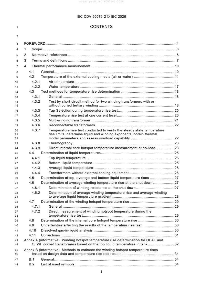
1 CONTENTS
3 FOREWORD . 4
4 1 Scope . 6
5 2 Normative references . 6
6 3 Terms and definitions . 7
7 4 Thermal performance measurement . 10
8 4.1 General . 10
9 4.2 Temperature of the external cooling media (air or water) . 11
10 4.2.1 Air temperature . 11
11 4.2.2 Water temperature . 17
12 4.3 Test methods for temperature rise determination . 18
13 4.3.1 General . 18
14 4.3.2 Test by short-circuit method for two winding transformers with or
15 without buried tertiary winding . 18
16 4.3.3 Tap Selection during temperature rise test . 20
17 4.3.4 Temperature rise test at one current level . 20
18 4.3.5 Multi-winding transformer . 21
19 4.3.6 Reconnectable transformers . 22
20 4.3.7 Temperature rise test conducted to verify the steady state temperature
21 rise limits, determine liquid and winding exponents, obtain thermal
22 model parameters and assess overload capability . 22
23 4.3.8 Thermography . 23
24 4.3.9 Direct internal core hotspot temperature measurement at no-load . 23
25 4.4 Determination of liquid temperatures . 25
26 4.4.1 Top liquid temperature . 25
27 4.4.2 Bottom liquid temperature . 25
28 4.4.3 Average liquid temperature . 26
29 4.4.4 Transformers without external cooling equipment . 26
30 4.5 Determination of top, average and bottom liquid temperature rises . 27
31 4.6 Determination of average winding temperature rise at the shut down . 27
32 4.6.1 Determination of winding resistance at the shut down . 27
33 4.6.2 Determination of average winding temperature rise and average winding
34 to average liquid temperature gradient . 28
35 4.7 Determination of the winding hotspot temperature rise . 29
36 4.7.1 General . 29
37 4.7.2 Direct measurement of winding hotspot temperature during the
38 temperature rise test . 29
39 4.8 Determination of the internal core hotspot temperature rise . 30
40 4.9 Uncertainties affecting the results of the temperature rise test . 30
41 4.10 Dissolved gas-in-liquid analysis . 30
42 4.11 Corrections . 31
43 Annex A (informative) Winding hotspot temperature rise determination for OFAF and
44 OFWF cooled transformers based on the top liquid temperature in tank. 32
45 Annex B (informative) Methods to estimate the winding hotspot temperature rises
46 based on design data and temperature rise test results . 34
47 B.1 General . 34
48 B.2 List of used symbols . 34
IEC CDV 60076-2 © IEC 2026
49 B.3 Determination by calculation based on design data . 34
50 B.4 Mathematical models for natural and direct forced liquid flow cooling
51 systems based on temperature rise test results . 35
52 B.4.1 Core type transformers . 35
53 B.4.2 Shell type transformers . 37
54 B.5 Mathematical models for forced liquid flow cooling systems . 37
55 Annex C (normative) Techniques used in temperature rise testing of liquid-immersed
56 transformers . 38
57 C.1 Winding resistance measurement after shut down . 38
58 C.1.1 Setting of the cooling equipment during the winding resistance
59 measurement . 38
60 C.1.2 Procedure for winding resistance measurement . 38
61 C.2 Extrapolation of winding temperature to the shut down . 42
62 C.3 A numerical extrapolation procedure of cooling down curve . 43
63 Annex D (informative) Dissolved gases analysis for the detection of overheating . 48
64 D.1 General . 48
65 D.2 Temperature rise test duration . 48
66 D.3 Sampling of liquid . 49
67 D.4 Gas analysis and result interpretation . 49
68 Annex E (informative) Application of optical fibre and thermocouple sensors for
69 winding hotspot measurements in transformer active and structural parts . 52
70 E.1 Direct measurement of winding hotspot temperature rise . 52
71 E.2 Direct measurement of hotspot temperature rise in core and structural parts . 54
72 E.3 Generic rule for determination of core surface and structural part
73 temperature rises . 56
74 Annex F (informative) Liquid and Winding exponents . 57
75 F.1 General . 57
76 F.2 Theoretical approach . 57
77 F.3 Extended temperature rise test approach . 59
78 Annex G (informative) Detection of the end of heat run test sequence with total loss
79 supply. 60
80 G.1 Scope . 60
81 G.2 References . 60
82 G.3 Terms and definitions . 60
83 G.4 Summary of total loss supply heat-run method (context) . 60
84 G.5 Data processing procedure (step-by-step) . 60
85 G.6 End-of-test detection criteria . 61
86 G.7 Reporting . 61
87 G.8 Parameterization and adjustable constraints . 61
88 G.9 Uncertainty and quality metrics . 62
89 G.10 Implementation traceability (Excel/VBA) . 62
90 G.11 Data-flow overview. 62
91 G.12 Disclaimer . 62
92 Annex H (informative) Typical Heat Sink . 63
93 H.1 Heat Sink Design . 63
94 Annex I (informative) Superposition method for winding resistance determination . 64
96 Figure 4-1 – Sensor location around AN cooled transformer without radiator and
97 external cooler, figure illustrates a general piece of cooling equipment . 14
IEC CDV 60076-2 © IEC 2026
98 Figure 4-2 – Sensor location around a transformer, AN cooling, figure illustrates a
99 general piece of cooling equipment . 15
100 Figure 4-3 – Example of sensor location around a vertically forced-cooled
101 transformer(.AF), figure illustrates a general piece of cooling equipment . 16
102 Figure 4-4 – Sensor location around a horizontally forced-cooled transformer(.AF)
103 equipped with radiators, figure illustrates a general piece of cooling equipment . 16
104 Figure 4-5 – Sensor location around a horizontally forced-cooled transformer with
105 radiators(.AF), figure illustrates a general piece of cooling equipment . 17
106 Figure 4-6 – Example sensor location around a transformer(.AF) equipped with liquid
107 to air heat exchanger . 17
108 Figure 4-7 – Example sensor location (.AF) equipped with separated liquid to air heat
109 exchanger . 18
110 Figure 4-8 – Example sensor location (.AF) equipped with liquid to air heat exchanger
111 attached to the tank wall . 18
112 Figure B.1 – Temperature rise distribution model . 37
113 Figure C.1 – Recommended circuit for transformers with a low resistance winding
114 using two separate direct current sources, one for each winding . 41
115 Figure C.2 – Alternative recommended circuit using only one direct current source for
116 both windings . 42
117 Figure C.3 – Average winding temperature variation - cooling down curve test . 43
118 Figure C.4 – Extrapolation of the cooling down curve , using the fitting curve 𝜽𝑾𝒕 =
119 𝑨𝟎 − 𝒌𝒕 + 𝑩𝒆 − 𝒕𝑻𝑾 . 46
120 Figure C.5 – Average winding temperature variation - cooling down curve test . 48
121 Figure E.1 – Temperature winding rises above top liquid temperature (in tank . 54
122 Figure E.2 – Coil edges, where the sensors should be located in the edge with the
123 higher calculated temperature rise . 55
124 Figure E.3 – Temperature rises above top liquid temperature at the end of an 8 h
125 thermal no-load test at 110 % supply voltage . 56
126 Figure F.1 – Transformer exponent estimation plots . 60
127 Figure G.1 – Data-flow chart . 63
128 Figure H.1 – Typical heat sink for air temperature measurement . 64
129 Figure I.1 – Connection circuit for superpositionBibliography . 65
132 Table 1 – Exponents for the corrections of temperature rise test results . 32
133 Table A.1 – Winding hotspot temperature rises for some specific transformers
134 determined from conventional heat run test data combined with calculated winding
135 hotspot temperature rise, and from direct fibre-optic measurements . 34
136 Table C.1 – Example of cooling down curve calculation spreadsheet . 47
137 Table C.3 – Example of cooling down curve calculation spreadsheet – method #2 . 48
138 Table D.1 – Minimum detectable value S of gases in liquid . 51
D
139 Table D.2 – Admissible limits for gas rate increases . 51
IEC CDV 60076-2 © IEC 2026
142 INTERNATIONAL ELECTROTECHNICAL COMMISSION
143 ____________
145 POWER TRANSFORMERS –
147 Part 2: Thermal performance measurement and test procedures for liquid-
148 immersed transformers
151 FOREWORD
152 1) The International Electrotechnical Commission (IEC) is a worldwide organization for standardization comprising
153 all national electrotechnical committees (IEC National Committees). The object of IEC is to promote international
154 co-operation on all questions concerning standardization in the electrical and electronic fields. To this end and
155 in addition to other activities, IEC publishes International Standards, Technical Specifications, Technical Reports,
156 Publicly Available Specifications (PAS) and Guides (hereafter referred to as “IEC Publication(s)”). Their
157 preparation is entrusted to technical committees; any IEC National Committee interested in the subject dealt with
158 may participate in this preparatory work. International, governmental and non-governmental organizations liaising
159 with the IEC also participate in this preparation. IEC collaborates closely with the International Organization for
160 Standardization (ISO) in accordance with conditions determined by agreement between the two organizations.
161 2) The formal decisions or agreements of IEC on technical matters express, as nearly as possible, an international
162 consensus of opinion on the relevant subjects since each technical committee has representation from all
163 interested IEC National Committees.
164 3) IEC Publications have the form of recommendations for international use and are accepted by IEC National
165 Committees in that sense. While all reasonable efforts are made to ensure that the technical content of IEC
166 Publications is accurate, IEC cannot be held responsible for the way in which they are used or for any
167 misinterpretation by any end user.
168 4) In order to promote international uniformity, IEC National Committees undertake to apply IEC Publications
169 transparently to the maximum extent possible in their national and regional publications. Any divergence between
170 any IEC Publication and the corresponding national or regional publication shall be clearly indicated in the latter.
171 5) IEC itself does not provide any attestation of conformity. Independent certification bodies provide conformity
172 assessment services and, in some areas, access to IEC marks of conformity. IEC is not responsible for any
173 services carried out by independent certification bodies.
174 6) All users should ensure that they have the latest edition of this publication.
175 7) No liability shall attach to IEC or its directors, employees, servants or agents including individual experts and
176 members of its technical committees and IEC National Committees for any personal injury, property damage or
177 other damage of any nature whatsoever, whether direct or indirect, or for costs (including legal fees) and
178 expenses arising out of the publication, use of, or reliance upon, this IEC Publication or any other IEC
179 Publications.
180 8) Attention is drawn to the Normative references cited in this publication. Use of the referenced publications is
181 indispensable for the correct application of this publication.
182 9) Attention is drawn to the possibility that some of the elements of this IEC Publication may be the subject of patent
183 rights. IEC shall not be held responsible for identifying any or all such patent rights.
184 International Standard IEC 60076-2 has been prepared by IEC technical committee 14: Power
185 transformers.
186 This first edition cancels and replaces the third edition published in 2011. It is a technical
187 revision.
188 This edition includes the following significant technical changes with respect to the previous
189 edition based on guidance provided by IEC TC 14 AHG 36:
190 a) the title is changed to: Thermal performance measurement and test procedures for liquid-
191 immersed transformers;
192 b) the scope is changed to: This part of IEC 60076 applies to liquid-immersed transformers,
193 verifies compliance with temperature requirements and gives the methods for temperature
194 rise tests;
195 c) the clauses 4, 5, and 6 are moved from edition 2011 to IEC 60076-1 revised document
196 including the temperature rise limits and ambient temperature reference values ;
IEC CDV 60076-2 © IEC 2026
197 d) the procedures for the temperature rise test were improved in relation to the new thermal
198 requirements;
199 e) the core temperature test and corresponding temperature rise determination is introduced;
200 f) annexes B, D and E are modified, and three informative annexes F, G, H and I are added
201 in order to facilitate the standard application.
203 The text of this standard is based on the following documents:
FDIS Report on voting
205 Full information on the voting for the approval of this standard can be found in the report on
206 voting indicated in the above table.
207 This publication has been drafted in accordance with the ISO/IEC Directives, Part 2.
208 A list of all parts of the IEC 60076 series can be found, under the general title Power
209 transformers, on the IEC website.
210 The committee has decided that the contents of this publication will remain unchanged until the
211 stability date indicated on the IEC web site under "http://webstore.iec.ch" in the data related to
212 the specific publication. At this date, the publication will be
213 • reconfirmed,
214 • withdrawn,
215 • replaced by a revised edition, or
216 • amended.
IMPORTANT – The 'colour inside' logo on the cover page of this publication indicates that it
contains colours which are considered to be useful for the correct understanding of its
contents. Users should therefore print this document using a colour printer.
IEC CDV 60076-2 © IEC 2026
220 POWER TRANSFORMERS –
222 Part 2: Thermal performance measurement and test procedures for liquid-
223 immersed transformers
226 1 Scope
227 This part of IEC 60076 applies to liquid-immersed transformers, verifies compliance with
228 temperature requirements and gives the methods for temperature rise tests.
229 2 Normative references
230 The following referenced documents are indispensable for the application of this document. For
231 dated references, only the edition cited applies. For undated references, the latest edition of
232 the referenced document (including any amendments) applies.
233 IEC 60076-1, Power transformers – Part 1: General
234 IEC 60076-7, Power transformers – Part 7: Loading guide for mineral-oil-immersed power
235 transformers
236 IEC 60076-8, Power transformers – Part 8: Application guide
237 IEC 61181, Mineral oil-filled electrical equipment – Application of dissolved gas analysis (DGA)
238 to factory tests on electrical equipment
239 IEC Guide 115, Application of measurement uncertainty to conformity assessment activities in
240 the electrotechnical sector
241 IEC 60076-19-1, Power transformers - Part 19 - 1: Rules for the determination of uncertainties
242 in the measurement of the losses of power transformers
243 IEC 60076-22-2, Power transformers - Part 22-2: Power transformer and reactor fittings -
244 Removable radiators
245 IEC 60076-22-3, Power transformers - Part 22-2: Power transformer and reactor fittings -
246 Insulating liquid to air heat exchangers
247 IEC 60076-22-6, Power transformers - Part 22-6: Power transformer and reactor fittings -
248 Electric fans for transformers
249 ISO 10880, Non-destructive testing — Infrared thermographic testing — General principles
250 IEC 60567, Oil-filled electrical equipment - Sampling of free gases and analysis of free and
251 dissolved gases in mineral oils and other insulating liquids – Guidance
IEC CDV 60076-2 © IEC 2026
255 3 Terms and definitions
256 For the purposes of this document, the terms and definitions given in IEC 60076-1 and the
257 following apply.
258 3.1
259 bottom liquid temperature
260 𝜽
𝒃
261 temperature of the liquid entering the bottom winding
262 3.2
263 bottom liquid temperature rise
264 𝜟𝜽
𝒃
265 difference between the bottom liquid temperature and the external cooling medium temperature
266 3.3
267 external cooling medium
268 fluid (air or water) external to the transformer cooling system (air or water) into which the heat
269 produced by the transformer losses is transferred
270 3.4
271 𝜽
𝒂
272 temperature of the external cooling medium
273 temperature of the external cooling medium outside the influence from the transformer
274 3.5
275 top liquid temperature
276 𝜽
𝒐
277 the temperature of the liquid at the top of the tank, representative of top liquid in the cooling
278 flow stream
279 3.6
280 top liquid temperature rise
281 𝜟𝜽
𝒐
282 difference between the top liquid temperature and the external cooling medium temperature
283 3.7
284 average liquid temperature
285 𝜽
𝒐𝒎
286 average temperature of the top liquid and bottom liquid temperatures
287 3.8
288 average liquid temperature rise
289 𝜟𝜽
𝒐𝒎
290 difference between the average liquid temperature and the external cooling medium
291 temperature
292 3.9
293 average liquid temperature rise at shut down
′
294 ∆𝜽
𝒐𝒎
295 difference between the average liquid temperature and the external cooling medium
296 temperature at shut down
297 3.10
298 winding temperature determined from resistance measurement
299 𝜽
𝟐
300 winding temperature determined from resistance measurements at shut down
IEC CDV 60076-2 © IEC 2026
301 3.11
302 average liquid temperature at shut down
′
303 𝜽
𝒐𝒎
304 average temperature of the top liquid and bottom liquid temperatures at shut down
305 3.12
306 average winding temperature
307 𝜽
𝒘
308 winding temperature determined at the end of temperature rise test from the measurement of
309 winding d.c. resistance
310 3.13
311 average winding temperature rise
312 ∆𝜽
𝒘
313 difference between the average winding temperature and the external cooling medium
314 temperature
315 3.14
316 average winding gradient
317 𝒈
318 difference between the average winding temperature and the average liquid temperature
319 3.15
320 winding hotspot to top liquid temperature gradient
321 ∆𝜽
𝒉−𝒐
322 difference between the winding hotspot temperature and the top liquid temperature
323 3.16
324 winding hottest temperature reading at shut down
′
325 𝜽
𝒉
326 hottest measured winding temperature of winding conductors in contact with solid insulation or
327 liquid at shut down
328 3.17
329 top liquid temperature at shut down
′
330 𝜽
𝒐
331 temperature of the insulating liquid at the top of the tank at shut down, representative of top
332 liquid in the cooling flow stream
333 3.18
334 hotspot factor
335 𝑯
336 dimensionless factor to estimate the local increase of the average winding gradient due to the
337 additional loss and variation in the liquid flow stream
338 3.19
339 winding hotspot temperature rise
340 ∆𝜽
𝒉
341 difference between the winding hotspot temperature and the external cooling medium
342 temperature
343 3.20
344 no-load top liquid temperature
345 𝜽
𝒄𝒐
346 temperature of the top liquid at the end of the no-load temperature rise test at the same tank
347 location as the top liquid temperature defined in 3.5
IEC CDV 60076-2 © IEC 2026
348 3.21
349 no-load bottom liquid temperature
350 𝜽
𝒄𝒃
351 temperature of the bottom liquid at the end of the no-load temperature rise test at the same
352 tank location as the bottom liquid temperature defined in 3.1.
353 3.22
354 internal core hotspot temperature
355 𝜽
𝒄
356 hottest core internal temperature determined from the no load temperature rise at highest core
357 excitation and the liquid temperatures relevant to the operating condition
358 3.23
359 internal core hotspot temperature rise
360 ∆𝜽
𝒄
361 the difference between the internal core hotspot temperature and the external cooling medium
362 temperature
363 3.24
364 shut down
365 instant when the power supply is switched off
366 3.25
367 cooling method
368 cooling media type and flow principles, coded by capital letters
IEC CDV 60076-2 © IEC 2026
369 4 Thermal performance measurement
370 4.1 General
371 The following subclauses describe the procedures for the determination of temperature and
372 temperature rise values during factory testing and also the methods for substituting service
373 loading conditions by equivalent test procedures.
374 The thermal performance measurement is carried out to verify the guaranteed temperature rises
375 in insulation liquid and windings as given in Clause 5.4.3 of IEC 60076-1.
376 NOTE Altitude correction of cooling conditions is given in Clause 5.5 of IEC 60076-1
377 The temperature rise test can also reveal overheating within the transformer due to conditions
378 such as stray flux heating and poor connections. The transformer loading capability can be
379 verified by direct measurement or by application of corresponding thermal models using the
380 data from the test.
381 During a temperature rise test various temperatures may be measured or derived, including:
382 • External cooling medium temperature
383 • Top liquid temperature
384 • Bottom liquid temperature
385 • Average liquid temperature
386 • Average winding temperatures
387 • Internal structural part temperatures
388 • Tank temperature
389 • Internal core hotspot temperature
390 • Winding hotspot temperature
391 NOTE Some of these measurements depend on the presence of temperature sensors
392 During the temperature rise test, the transformer shall be equipped with any relevant protective
393 devices that would be present in service and are within the scope of the contract between
394 customer and manufacturer. Any indication from these devices during the test shall be noted
395 and the case investigated.
396 For transformers designed with alternative cooling method ratings, a temperature rise test shall be
397 performed for each cooling method rating to determine the corresponding temperature rises and
398 thermal parameters. By agreement between manufacturer and customer, the testing may be reduced
399 to the test at the nominal power of the transformer if customer accepts to use the calculated
400 parameters for the other cooling method power ratings.
IEC CDV 60076-2 © IEC 2026
402 4.2 Temperature of the external cooling media (air or water)
403 The external cooling medium is defined by the third letter code in the cooling method (see IEC 60076-
404 1, Clause 5.2.2)
405 4.2.1 Air temperature
406 For the temperature rise test, the external cooling medium temperature shall be between 10 °C and
407 the maximum external cooling medium temperature at which the winding hotspot temperature shall not
408 exceed the long-time emergency loading temperature limit specified in IEC 60076-7, or the limit
409 specified by the customer, at any point during the test.
410 Where direct winding hotspot measurement is not provided, compliance with this limit shall be
411 assessed by calculation using the measured external cooling medium temperature, the measured
412 liquid temperature, and the calculated winding hotspot-to-top-liquid temperature gradient. The
413 calculation basis shall be documented in the test report.
414 Precautions shall be taken to minimize variations of cooling-air temperature, during the whole test
415 period. Rapid variations in readings shall be prevented by using heat sinks or ambient cans for the
416 temperature sensors. The thermal time constant of the heat sinks shall be approximately 2,5 h,
417 suitable for all transformer designs. A report stating the heat-sink thermal time constant shall be
418 provided by the manufacturer. Informative Annex H provides an example of a heat-sink design that
419 fulfils the time-constant requirement.
420 NOTE. The time constant of a container (heat sink or ambient can) shall be taken as the time necessary for its
421 temperature to change 6,3 K when the ambient temperature is abruptly changed 10 K.
422 An alternative is to use an ambient temperature sensor with a time constant less than that of the
423 transformer but not less than 30 min and the ambient temperature sampling interval is less than 10%
424 of the sensor time constant. Then any variations may be smoothed by applying a moving-average filter
425 over the period of 2,5 h in the real time.
426 The sensors should be protected from direct heat radiation from the tank and other heat sources.
427 Readings should be taken at regular intervals not exceeding 5 min or at shorter intervals if
428 agreed between customer and manufacturer. These readings should be synchronized with other
429 temperature measurements and recorded automatically and continuously.
430 The temperature rise test shall be done as in service with a stable environment regulated by
431 the airflow management, e.g. by positioning the transformer away from open doors, ports or
432 ventilation outlets, and by balancing ventilation to ensure that the air exchange rate is sufficient
433 for fresh air without affecting temperature stability. Temporary use of doors or ports shall be
434 permitted only where it does not affect the readings of the temperature sensors. During the last
435 four hours of the test, any change in test-bay ventilation and any use of doors or ports shall not
436 be permitted.
437 The distance between the tank including cooling equipment and any object including the
438 laboratory walls, (excluding testing equipment), shall be more than 3 m.
439 In the case of separate cooling equipment placed at a distance greater than 3 m from the
440 transformer tank, the ambient temperature shall be measured around the cooling equipment
441 applying the same rules given below. When the separate cooling equipment is placed at a
442 distance of less than 3 m, the ambient temperature shall be measured as defined below for the
443 cooling equipment mounted on the tank.
444 The transformer shall be positioned so as to minimise obstructions to the airflow and local
445 recirculation of hot air, and to ensure stable and evenly distributed ambient conditions .
446 In case of cooling equipment mounted on the tank, it is not allowed to install any ambient
447 temperature sensor between the tank and the cooling equipment.
IEC CDV 60076-2 © IEC 2026
448 The position of the ambient temperature sensors shall be selected in accordance with the
449 applicable cooling method for transformers with multiple cooling methods.
IEC CDV 60076-2 © IEC 2026
451 4.2.1.1 AN cooled transformers
452 At least four sensors shall be provided, and the average of their readings shall be used to
453 determine the temperature of external cooling medium for the evaluation of the test results. For
454 tests on large power transformers, 100 MVA and above, the number of provided sensors shall
455 be at least six.
456 NOTE Attention to be paid at the beginning of the stabilization period, see 4.3.2.1, to identify any faulty sensors or
457 not properly located.
458 i. without external radiators
459 Around a naturally cooled transformer (.AN) equipped with corrugated tank or without any external
460 cooling equipment, the ambient sensors shall be placed halfway up of the cooling vertical tank wall
461 surface. The sensors shall be distributed around the transformer tank and 2 m away from the
462 corrugated tank or the vertical cooling surface, Figure 4.1.
465 Figure 4-1 – Sensor location around AN cooled transformer without radiator and
466 external cooler, figure illustrates a general piece of cooling equipment
467 ii. with radiators
468 Around a naturally cooled transformer (.AN) equipped with radiators, the ambient sensors shall be
469 placed ¼ way up the radiator vertical cooling surface see Figure 4.2. The sensors shall be installed
470 around the transformer tank and the cooling equipment, maintaining a distance of 2 m from their
471 surfaces.
IEC CDV 60076-2 © IEC 2026
473 Figure 4-2 – Sensor location around a transformer, AN cooling, figure illustrates a
474 general piece of cooling equipment
476 4.2.1.2 AF cooled transformers
477 The number of sensors shall correspond to the number of fans up to four. Above the four fans,
478 the ambient sensors shall be uniformly distributed over the air intake area of AF equipment.
479 The average of their readings shall be used to determine the temperature of external cooling
480 medium for the evaluation of the test results.
481 NOTE Attention to be paid at the beginning of the stabilization period, see 4.3.2, to identify any faulty sensors or not
482 properly located.
484 i. vertically forced air through radiators
486 For a transformer equipped with radiators according to IEC 60076-22-2 or similar and fans according
487 to IEC 6076-22-6 or similar where the fans blow vertically, (.AF), the sensors shall be placed 0,5 m
488 from the air intake of the cooling equipment.
489 As indicated in Figure 4.3, the sensor shall be placed at the outer perimeter of the fan housing, at the
490 point furthest from the transformer tank.
491 Symbols for the fan and the corresponding housing in the following figures are:
492 , .
IEC CDV 60076-2 © IEC 2026
Top view
Side view
Cooling
Equipment
Tank
Tank
Cooling
Equipment
Blowing
direction
0,5 m
sensor
495 Figure 4-3 – Example of sensor location around a vertically forced-cooled
496 transformer(.AF), figure illustrates a general piece of cooling equipment
497 ii. horizontally forced air through radiators
498 For a transformer equipped with radiators according to IEC 60076-22-2 or similar and fans according
499 to IEC 6076-22-6 or similar, where the fans blow horizontally, (.AF), the sensors shall, where
500 applicable, be placed as indicated in Figure 4.4, Figure 4.5 and Figure 4.6, at the level of lowest and
501 highest fans on the bottom outer perimeter of the fan housing. The sensor shall be located at a
502 distance of 0,5 m or 1 m from the air intake side, as indicated in Figure 4.4, Figure 4.5 and Figure 4.6,
503 depending on blowing directions. The average of their readings shall be used to determine the
504 temperature of external cooling medium for the evaluation of the test results.
506 Figure 4-4 – Sensor location around a horizontally forced-cooled transformer(.AF)
507 equipped with radiators, figure illustrates a general piece of cooling equipment
IEC CDV 60076-2 © IEC 2026
509 Figure 4-5 – Sensor location around a horizontally forced-cooled transformer with
510 radiators(.AF), figure illustrates a general piece of cooling equipment
511 iii. horizontally forced air through heat exchangers
513 The sensors shall be placed in the horizontal plane on the bottom outer perimeter of the fan housing,
514 as shown in Figure 4.6, at the level of lowest and highest fans, where applicable. They shall be
515 located 0,5 m and 1 m from the air intake, in the directions indicated, depending on blowing direction.
516 The average of their readings shall be used to determine the temperature of external cooling medium
517 for the evaluation of the test results. Additional examples, with the heat exchanger separated from the
518 tank and attached to the tank wall, are shown in Figure 4.7 and Figure 4.8 respectively.
519 Transformer with liquid to air heat exchanger (air blast coolers) according to IEC 60076-22-3 or
520 similar.
522 Figure 4-6 – Example sensor location around a transformer(.AF) equipped with liquid to
523 air heat exchanger
IEC CDV 60076-2 © IEC 2026
525 Figure 4-7 – Example sensor location (.AF) equipped with separated liquid to air heat
526 exchanger
528 Figure 4-8 – Example sensor location (.AF) equipped with liquid to air heat exchanger
529 attached to the tank wall
530 4.2.2 Water temperature
531 For the temperature rise test, the cooling water temperature should be in the range between
532 5 °C and the maximum water temperature for which the transformer is designed.
533 The temperature shall be measured at the intake of the cooling equipment. Readings of
534 temperature and rate of water flow shall be taken at regular intervals (e.g., the water flow rate
535 every 10 min and the temperature every 5 min, to be synchronized with other temperature
536 measurements), by automatic continuous recording. If more than one intake is used the flow
537 weighted average temperature shall be used as temperature of external cooling medium.
538 Precautions shall be taken to minimize the variations of water-cooling flow and temperature
539 during the test period.
IEC CDV 60076-2 © IEC 2026
540 4.3 Test methods for temperature rise determination
541 4.3.1 General
542 The standard method for the determination of the steady-state temperature rises on the test
543 floor is the equivalent test in short-circuit connection according to 4.3.2 below. In special cases,
544 if agreed, th
...