


ASTM E1922-04(2015)
(Test Method)Standard Test Method for Translaminar Fracture Toughness of Laminated and Pultruded Polymer Matrix Composite Materials
Standard Test Method for Translaminar Fracture Toughness of Laminated and Pultruded Polymer Matrix Composite Materials
SIGNIFICANCE AND USE
5.1 The parameter KTL determined by this test method is a measure of the resistance of a polymer matrix composite laminate to notch-tip damage and effective translaminar crack growth under opening mode loading. The result is valid only for conditions in which the damage zone at the notch tip is small compared with the notch length and the in-plane specimen dimensions.
5.2 This test method can serve the following purposes. In research and development, KTL data can quantitatively establish the effects of fiber and matrix variables and stacking sequence of the laminate on the translaminar fracture resistance of composite laminates. In acceptance and quality control specifications, KTL data can be used to establish criteria for material processing and component inspection.
5.3 The translaminar fracture toughness, KTL, determined by this test method may be a function of the testing speed and temperature. This test method is intended for room temperature and quasi-static conditions, but it can apply to other test conditions provided that the requirements of 9.2 and 9.3 are met. Application of KTL in the design of service components should be made with awareness that the test parameters specified by this test may differ from service conditions, possibly resulting in a different material response than that seen in service.
5.4 Not all types of laminated polymer matrix composite materials experience the contained notch-tip damage and effective translaminar crack growth of concern in this test method. For example, the notch-tip damage may be more extensive and may not be accompanied by any significant amount of effective translaminar crack growth. Typically, lower strength composite materials and those with a significant proportion of reinforcing fibers aligned in a direction perpendicular to the notch axis may not experience the contained notch-tip damage required for a valid test.
SCOPE
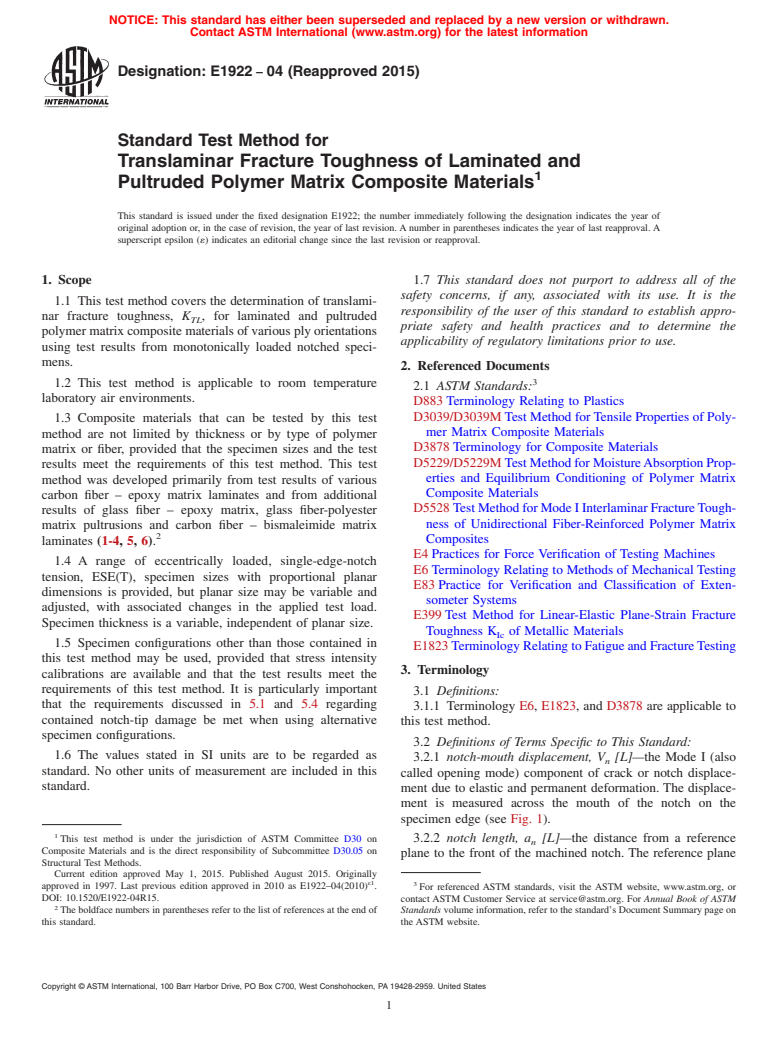
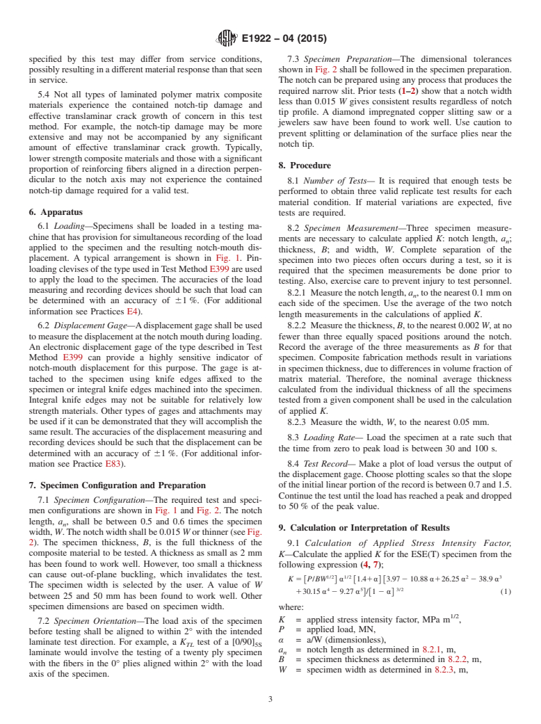
1.1 This test method covers the determination of translaminar fracture toughness, KTL, for laminated and pultruded polymer matrix composite materials of various ply orientations using test results from monotonically loaded notched specimens.
1.2 This test method is applicable to room temperature laboratory air environments.
1.3 Composite materials that can be tested by this test method are not limited by thickness or by type of polymer matrix or fiber, provided that the specimen sizes and the test results meet the requirements of this test method. This test method was developed primarily from test results of various carbon fiber – epoxy matrix laminates and from additional results of glass fiber – epoxy matrix, glass fiber-polyester matrix pultrusions and carbon fiber – bismaleimide matrix laminates (1-4, 5, 6).2
1.4 A range of eccentrically loaded, single-edge-notch tension, ESE(T), specimen sizes with proportional planar dimensions is provided, but planar size may be variable and adjusted, with associated changes in the applied test load. Specimen thickness is a variable, independent of planar size.
1.5 Specimen configurations other than those contained in this test method may be used, provided that stress intensity calibrations are available and that the test results meet the requirements of this test method. It is particularly important that the requirements discussed in 5.1 and 5.4 regarding contained notch-tip damage be met when using alternative specimen configurations.
1.6 The values stated in SI units are to be regarded as standard. No other units of measurement are included in this standard.
1.7 This standard does not purport to address all of the safety concerns, if any, associated with its use. It is the responsibility of the user of this standard to establish appropriate safety and health practices and to determine the applicability of regulatory limitations prior to use.
General Information
Buy Standard
Standards Content (Sample)
NOTICE: This standard has either been superseded and replaced by a new version or withdrawn.
Contact ASTM International (www.astm.org) for the latest information
Designation: E1922 − 04 (Reapproved 2015)
Standard Test Method for
Translaminar Fracture Toughness of Laminated and
Pultruded Polymer Matrix Composite Materials
This standard is issued under the fixed designation E1922; the number immediately following the designation indicates the year of
original adoption or, in the case of revision, the year of last revision. A number in parentheses indicates the year of last reapproval. A
superscript epsilon (´) indicates an editorial change since the last revision or reapproval.
1. Scope 1.7 This standard does not purport to address all of the
safety concerns, if any, associated with its use. It is the
1.1 This test method covers the determination of translami-
responsibility of the user of this standard to establish appro-
nar fracture toughness, K , for laminated and pultruded
TL
priate safety and health practices and to determine the
polymer matrix composite materials of various ply orientations
applicability of regulatory limitations prior to use.
using test results from monotonically loaded notched speci-
mens.
2. Referenced Documents
1.2 This test method is applicable to room temperature
2.1 ASTM Standards:
laboratory air environments.
D883 Terminology Relating to Plastics
D3039/D3039M Test Method for Tensile Properties of Poly-
1.3 Composite materials that can be tested by this test
mer Matrix Composite Materials
method are not limited by thickness or by type of polymer
D3878 Terminology for Composite Materials
matrix or fiber, provided that the specimen sizes and the test
D5229/D5229M TestMethodforMoistureAbsorptionProp-
results meet the requirements of this test method. This test
erties and Equilibrium Conditioning of Polymer Matrix
method was developed primarily from test results of various
Composite Materials
carbon fiber – epoxy matrix laminates and from additional
D5528 TestMethodforModeIInterlaminarFractureTough-
results of glass fiber – epoxy matrix, glass fiber-polyester
ness of Unidirectional Fiber-Reinforced Polymer Matrix
matrix pultrusions and carbon fiber – bismaleimide matrix
Composites
laminates (1-4, 5, 6).
E4 Practices for Force Verification of Testing Machines
1.4 A range of eccentrically loaded, single-edge-notch
E6 Terminology Relating to Methods of Mechanical Testing
tension, ESE(T), specimen sizes with proportional planar
E83 Practice for Verification and Classification of Exten-
dimensions is provided, but planar size may be variable and
someter Systems
adjusted, with associated changes in the applied test load.
E399 Test Method for Linear-Elastic Plane-Strain Fracture
Specimen thickness is a variable, independent of planar size.
Toughness K of Metallic Materials
Ic
1.5 Specimen configurations other than those contained in
E1823 TerminologyRelatingtoFatigueandFractureTesting
this test method may be used, provided that stress intensity
3. Terminology
calibrations are available and that the test results meet the
requirements of this test method. It is particularly important
3.1 Definitions:
that the requirements discussed in 5.1 and 5.4 regarding
3.1.1 Terminology E6, E1823, and D3878 are applicable to
contained notch-tip damage be met when using alternative
this test method.
specimen configurations.
3.2 Definitions of Terms Specific to This Standard:
1.6 The values stated in SI units are to be regarded as
3.2.1 notch-mouth displacement, V [L]—the Mode I (also
n
standard. No other units of measurement are included in this
called opening mode) component of crack or notch displace-
standard.
ment due to elastic and permanent deformation. The displace-
ment is measured across the mouth of the notch on the
specimen edge (see Fig. 1).
This test method is under the jurisdiction of ASTM Committee D30 on
3.2.2 notch length, a [L]—the distance from a reference
n
Composite Materials and is the direct responsibility of Subcommittee D30.05 on
plane to the front of the machined notch. The reference plane
Structural Test Methods.
Current edition approved May 1, 2015. Published August 2015. Originally
ε1
approved in 1997. Last previous edition approved in 2010 as E1922–04(2010) . For referenced ASTM standards, visit the ASTM website, www.astm.org, or
DOI: 10.1520/E1922-04R15. contact ASTM Customer Service at service@astm.org. For Annual Book of ASTM
The boldface numbers in parentheses refer to the list of references at the end of Standards volume information, refer to the standard’s Document Summary page on
this standard. the ASTM website.
Copyright © ASTM International, 100 Barr Harbor Drive, PO Box C700, West Conshohocken, PA 19428-2959. United States
E1922 − 04 (2015)
FIG. 1 Test Arrangement for Translaminar Fracture Toughness Tests
depends on the specimen form, and normally is taken to be samples and for samples with a significant proportion of the
eithertheboundary,oraplanecontainingeithertheloadlineor near surface reinforcing fibers aligned parallel to the direction
the centerline of a specimen or plate. The reference plane is of the notch.
defined prior to specimen deformation (see Fig. 2).
5. Significance and Use
3.2.3 normalized notch size, a /W [nd]—the ratio of notch
n
length, a , to specimen width, W.
n
5.1 The parameter K determined by this test method is a
TL
3.2.4 For additional information, see Terminology D883 measure of the resistance of a polymer matrix composite
and Test Methods D3039/D3039M, D5229/D5229M, and
laminate to notch-tip damage and effective translaminar crack
D5528.
growth under opening mode loading. The result is valid only
for conditions in which the damage zone at the notch tip is
4. Summary of Test Method
small compared with the notch length and the in-plane speci-
4.1 This test method involves tension testing of eccentri- men dimensions.
cally loaded, single-edge-notch, ESE(T), specimens in opening
5.2 This test method can serve the following purposes. In
mode loading. Load versus displacement across the notch at
research and development, K data can quantitatively estab-
TL
the specimen edge, V , is recorded. The load corresponding to
n
lish the effects of fiber and matrix variables and stacking
aprescribedincreaseinnormalizednotchlengthisdetermined,
sequenceofthelaminateonthetranslaminarfractureresistance
using the load-displacement record. The translaminar fracture
of composite laminates. In acceptance and quality control
toughness, K , is calculated from this load using equations
TL
specifications, K data can be used to establish criteria for
TL
that have been established on the basis of elastic stress analysis
material processing and component inspection.
of the modified single-edge notched specimen.
5.3 Thetranslaminarfracturetoughness,K ,determinedby
4.2 The validity of translaminar fracture toughness, K ,
TL
TL
this test method may be a function of the testing speed and
determined by this test method depends on maintaining a
temperature.Thistestmethodisintendedforroomtemperature
relatively contained area of damage at the notch tip. To
and quasi-static conditions, but it can apply to other test
maintain this suitable notch-tip condition, the allowed increase
conditions provided that the requirements of 9.2 and 9.3 are
in notch-mouth displacement near the maximum load point of
the tests is limited to a small value. Small increases in met. Application of K in the design of service components
TL
notch-mouth displacement are more likely for relatively thick
should be made with awareness that the test parameters
NOTE 1—All dimensions +/– 0.01 W, except as noted.
NOTE 2—A surfaces perpendicular and parallel as applicable within 0.01 W.
FIG. 2 Translaminar Fracture Toughness Test Specimen
E1922 − 04 (2015)
specified by this test may differ from service conditions, 7.3 Specimen Preparation—The dimensional tolerances
possiblyresultinginadifferentmaterialresponsethanthatseen shown in Fig. 2 shall be followed in the specimen preparation.
in service. The notch can be prepared using any process that produces the
required narrow slit. Prior tests (1–2) show that a notch width
5.4 Not all types of laminated polymer matrix composite
less than 0.015 W gives consistent results regardless of notch
materials experience the contained notch-tip damage and
tip profile. A diamond impregnated copper slitting saw or a
effective translaminar crack growth of concern in this test
jewelers saw have been found to work well. Use caution to
method. For example, the notch-tip damage may be more
prevent splitting or delamination of the surface plies near the
extensive and may not be accompanied by any significant
notch tip.
amount of effective translaminar crack growth. Typically,
lower strength composite materials and those with a significant
8. Procedure
proportion of reinforcing fibers aligned in a direction perpen-
dicular to the notch axis may not experience the contained
8.1 Number of Tests— It is required that enough tests be
notch-tip damage required for a valid test.
performed to obtain three valid replicate test results for each
material condition. If material variations are expected, five
6. Apparatus
tests are required.
6.1 Loading—Specimens shall be loaded in a testing ma-
8.2 Specimen Measurement—Three specimen measure-
chine that has provision for simultaneous recording of the load
ments are necessary to calculate applied K: notch length, a ;
n
applied to the specimen and the resulting notch-mouth dis-
thickness, B; and width, W. Complete separation of the
placement. A typical arrangement is shown in Fig. 1. Pin-
specimen into two pieces often occurs during a test, so it is
loading clevises of the type used inTest Method E399 are used
required that the specimen measurements be done prior to
to apply the load to the specimen. The accuracies of the load
testing. Also, exercise care to prevent injury to test personnel.
measuring and recording devices should be such that load can
8.2.1 Measurethenotchlength, a ,tothenearest0.1mmon
n
be determined with an accuracy of 61 %. (For additional
each side of the specimen. Use the average of the two notch
information see Practices E4).
length measurements in the calculations of applied K.
6.2 Displacement
...
This document is not an ASTM standard and is intended only to provide the user of an ASTM standard an indication of what changes have been made to the previous version. Because
it may not be technically possible to adequately depict all changes accurately, ASTM recommends that users consult prior editions as appropriate. In all cases only the current version
of the standard as published by ASTM is to be considered the official document.
´1
Designation: E1922 − 04 (Reapproved 2010) E1922 − 04 (Reapproved 2015)
Standard Test Method for
Translaminar Fracture Toughness of Laminated and
Pultruded Polymer Matrix Composite Materials
This standard is issued under the fixed designation E1922; the number immediately following the designation indicates the year of
original adoption or, in the case of revision, the year of last revision. A number in parentheses indicates the year of last reapproval. A
superscript epsilon (´) indicates an editorial change since the last revision or reapproval.
ε NOTE—1.6 and 3.2.1 were editorially updated in January 2011.
1. Scope
1.1 This test method covers the determination of translaminar fracture toughness, K , for laminated and pultruded polymer
TL
matrix composite materials of various ply orientations using test results from monotonically loaded notched specimens.
1.2 This test method is applicable to room temperature laboratory air environments.
1.3 Composite materials that can be tested by this test method are not limited by thickness or by type of polymer matrix or fiber,
provided that the specimen sizes and the test results meet the requirements of this test method. This test method was developed
primarily from test results of various carbon fiber – epoxy matrix laminates and from additional results of glass fiber – epoxy
matrix, glass fiber-polyester matrix pultrusions and carbon fiber – bismaleimide matrix laminates (1-4, 5, 6).
1.4 A range of eccentrically loaded, single-edge-notch tension, ESE(T), specimen sizes with proportional planar dimensions is
provided, but planar size may be variable and adjusted, with associated changes in the applied test load. Specimen thickness is a
variable, independent of planar size.
1.5 Specimen configurations other than those contained in this test method may be used, provided that stress intensity
calibrations are available and that the test results meet the requirements of this test method. It is particularly important that the
requirements discussed in 5.1 and 5.4 regarding contained notch-tip damage be met when using alternative specimen
configurations.
1.6 The values stated in SI units are to be regarded as standard. No other units of measurement are included in this standard.
1.7 This standard does not purport to address all of the safety concerns, if any, associated with its use. It is the responsibility
of the user of this standard to establish appropriate safety and health practices and to determine the applicability of regulatory
limitations prior to use.
2. Referenced Documents
2.1 ASTM Standards:
D883 Terminology Relating to Plastics
D3039/D3039M Test Method for Tensile Properties of Polymer Matrix Composite Materials
D3878 Terminology for Composite Materials
D5229/D5229M Test Method for Moisture Absorption Properties and Equilibrium Conditioning of Polymer Matrix Composite
Materials
D5528 Test Method for Mode I Interlaminar Fracture Toughness of Unidirectional Fiber-Reinforced Polymer Matrix Composites
E4 Practices for Force Verification of Testing Machines
E6 Terminology Relating to Methods of Mechanical Testing
E83 Practice for Verification and Classification of Extensometer Systems
E399 Test Method for Linear-Elastic Plane-Strain Fracture Toughness K of Metallic Materials
Ic
E1823 Terminology Relating to Fatigue and Fracture Testing
This test method is under the jurisdiction of ASTM Committee E08 on Fatigue and Fracture and is the direct responsibility of Subcommittee E08.05 on Cyclic
Deformation and Fatigue Crack Formation.
Current edition approved Oct. 1, 2010May 1, 2015. Published January 2011August 2015. Originally approved in 1997. Last previous edition approved in 20042010 as
ε1
E1922–04.E1922–04(2010) . DOI: 10.1520/E1922-04R10E01.10.1520/E1922-04R15.
The boldface numbers in parentheses refer to the list of references at the end of this standard.
For referenced ASTM standards, visit the ASTM website, www.astm.org, or contact ASTM Customer Service at service@astm.org. For Annual Book of ASTM Standards
volume information, refer to the standard’s Document Summary page on the ASTM website.
Copyright © ASTM International, 100 Barr Harbor Drive, PO Box C700, West Conshohocken, PA 19428-2959. United States
E1922 − 04 (2015)
3. Terminology
3.1 Definitions:
3.1.1 Terminology E6, E1823, and D3878 are applicable to this test method.
3.2 Definitions of Terms Specific to This Standard:
3.2.1 notch-mouth displacement, V [L]—the Mode I (also called opening mode) component of crack or notch displacement due
n
to elastic and permanent deformation. The displacement is measured across the mouth of the notch on the specimen edge (see Fig.
1).
3.2.2 notch length, a [L]—the distance from a reference plane to the front of the machined notch. The reference plane depends
n
on the specimen form, and normally is taken to be either the boundary, or a plane containing either the load line or the centerline
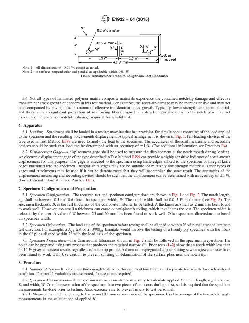
of a specimen or plate. The reference plane is defined prior to specimen deformation (see Fig. 2).
3.2.3 normalized notch size, a /W [nd]—the ratio of notch length, a , to specimen width, W.
n n
3.2.4 For additional information, see Terminology D883 and Test Methods D3039/D3039M, D5229/D5229M, and D5528.
4. Summary of Test Method
4.1 This test method involves tension testing of eccentrically loaded, single-edge-notch, ESE(T), specimens in opening mode
loading. Load versus displacement across the notch at the specimen edge, V , is recorded. The load corresponding to a prescribed
n
increase in normalized notch length is determined, using the load-displacement record. The translaminar fracture toughness, K ,
TL
is calculated from this load using equations that have been established on the basis of elastic stress analysis of the modified
single-edge notched specimen.
4.2 The validity of translaminar fracture toughness, K , determined by this test method depends on maintaining a relatively
TL
contained area of damage at the notch tip. To maintain this suitable notch-tip condition, the allowed increase in notch-mouth
displacement near the maximum load point of the tests is limited to a small value. Small increases in notch-mouth displacement
are more likely for relatively thick samples and for samples with a significant proportion of the near surface reinforcing fibers
aligned parallel to the direction of the notch.
5. Significance and Use
5.1 The parameter K determined by this test method is a measure of the resistance of a polymer matrix composite laminate
TL
to notch-tip damage and effective translaminar crack growth under opening mode loading. The result is valid only for conditions
in which the damage zone at the notch tip is small compared with the notch length and the in-plane specimen dimensions.
5.2 This test method can serve the following purposes. In research and development, K data can quantitatively establish the
TL
effects of fiber and matrix variables and stacking sequence of the laminate on the translaminar fracture resistance of composite
laminates. In acceptance and quality control specifications, K data can be used to establish criteria for material processing and
TL
component inspection.
5.3 The translaminar fracture toughness, K , determined by this test method may be a function of the testing speed and
TL
temperature. This test method is intended for room temperature and quasi-static conditions, but it can apply to other test conditions
provided that the requirements of 9.2 and 9.3 are met. Application of K in the design of service components should be made with
TL
awareness that the test parameters specified by this test may differ from service conditions, possibly resulting in a different material
response than that seen in service.
FIG. 1 Test Arrangement for Translaminar Fracture Toughness Tests
E1922 − 04 (2015)
NOTE 1—All dimensions +/– 0.01 W, except as noted.
NOTE 2—A surfaces perpendicular and parallel as applicable within 0.01 W.
FIG. 2 Translaminar Fracture Toughness Test Specimen
5.4 Not all types of laminated polymer matrix composite materials experience the contained notch-tip damage and effective
translaminar crack growth of concern in this test method. For example, the notch-tip damage may be more extensive and may not
be accompanied by any significant amount of effective translaminar crack growth. Typically, lower strength composite materials
and those with a significant proportion of reinforcing fibers aligned in a direction perpendicular to the notch axis may not
experience the contained notch-tip damage required for a valid test.
6. Apparatus
6.1 Loading—Specimens shall be loaded in a testing machine that has provision for simultaneous recording of the load applied
to the specimen and the resulting notch-mouth displacement. A typical arrangement is shown in Fig. 1. Pin-loading clevises of the
type used in Test Method E399 are used to apply the load to the specimen. The accuracies of the load measuring and recording
devices should be such that load can be determined with an accuracy of 61 %. (For additional information see Practices E4).
6.2 Displacement Gage—A displacement gage shall be used to measure the displacement at the notch mouth during loading.
An electronic displacement gage of the type described in Test Method E399 can provide a highly sensitive indicator of notch-mouth
displacement for this purpose. The gage is attached to the specimen using knife edges affixed to the specimen or integral knife
edges machined into the specimen. Integral knife edges may not be suitable for relatively low strength materials. Other types of
gages and attachments may be used if it can be demonstrated that they will accomplish the same result. The accuracies of the
displacement measuring and recording devices should be such that the displacement can be determined with an accuracy of 61 %.
(For additional information see Practice E83).
7. Specimen Configuration and Preparation
7.1 Specimen Configuration—The required test and specimen configurations are shown in Fig. 1 and Fig. 2. The notch length,
a , shall be between 0.5 and 0.6 times the specimen width, W. The notch width shall be 0.015 W or thinner (see Fig. 2). T
...
Questions, Comments and Discussion
Ask us and Technical Secretary will try to provide an answer. You can facilitate discussion about the standard in here.