


ASTM E1216-11(2016)
(Practice)Standard Practice for Sampling for Particulate Contamination by Tape Lift
Standard Practice for Sampling for Particulate Contamination by Tape Lift
SIGNIFICANCE AND USE
3.1 The tape lift provides a rapid and simple technique for removing particles from a surface and determining their number and size distribution.
3.2 By using statistically determined sample size and locations, an estimate of the surface cleanliness level of large areas can be made. The user shall define the sampling plan.
3.3 The sampling plan shall consider the importance of surface geometry and surface orientation to gas flow, gravity, obstructions, and previous history of hardware. These factors influence particle fallout and entrapment of particles on the surface. The geometry of joints, recessed areas, fasteners, and the correspondence of particle-count data to area can be maintained.
3.4 The selection of tape and the verification of its effect on the cleanliness of the hardware is very important. The tape adhesive should have sufficient cohesion to avoid transfer of the adhesive to the surface under test. The impact of adhesive transfer should be evaluated by laboratory testing before using the tape on the hardware. Since potential for adhesive transfer exists, cleaning to remove any adhesive might be required. In addition, the tape should have low outgassing characteristics, and as a minimum, it should meet the requirements of less than 1.0 % total mass loss (TML) and 0.1 % collected volatile condensable materials (CVCM), as measured by Test Method E595.
3.5 Care should be exercised in deciding which surfaces should be tested by this practice. The tape can remove marginally adhering paint and coatings. Optical surfaces should not be tested until verification has been made that the surface coating will not be damaged. Rough surface finishes result in low removal efficiencies. Surface finishes up to approximately 3.20 μm (125 μin.) have been tested and found to give satisfactory results.
3.6 This practice has been tested only on surfaces at room temperature. Evaluation of temperature effects must be conducted prior to using the test on surfaces ...
SCOPE
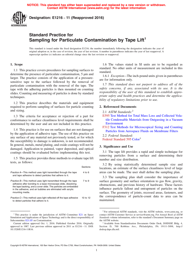
1.1 This practice covers procedures for sampling surfaces to determine the presence of particulate contamination, 5 μm and larger. The practice consists of the application of a pressure-sensitive tape to the surface followed by the removal of particulate contamination with the removal of the tape. The tape with the adhering particles is then mounted on counting slides. Counting and measuring of particles is done by standard techniques.
1.2 This practice describes the materials and equipment required to perform sampling of surfaces for particle counting and sizing.
1.3 The criteria for acceptance or rejection of a part for conformance to surface cleanliness level requirements shall be determined by the user and are not included in this practice.
1.4 This practice is for use on surfaces that are not damaged by the application of adhesive tape. The use of this practice on any surface of any material not previously tested, or for which the susceptibility to damage is unknown, is not recommended. In general, metals, metal plating, and oxide coatings will not be damaged. Application to painted, vapor deposited, and optical coatings should be evaluated before implementing this test.
1.5 This practice provides three methods to evaluate tape lift tests, as follows:
Sections
Practice A—This method uses light transmitted through the tape
and tape adhesive to detect particles that adhere to it.
4 to 6
Practice B—This method uses light transmitted through the tape
adhesive after bonding to a base microscope slide, dissolving
the tape backing, and a cover slide. The particles are embedded
in the adhesive, and air bubbles are eliminated with acrylic
mounting media.
7 to 9
Practice C—This method uses light reflected off the tape adhesive
to detect particles that adhere to it.
10 to 12
1.6 The values stated in SI units are to be regarded as standard...
General Information
Buy Standard
Standards Content (Sample)
NOTICE: This standard has either been superseded and replaced by a new version or withdrawn.
Contact ASTM International (www.astm.org) for the latest information
Designation: E1216 − 11 (Reapproved 2016)
Standard Practice for
Sampling for Particulate Contamination by Tape Lift
This standard is issued under the fixed designation E1216; the number immediately following the designation indicates the year of
original adoption or, in the case of revision, the year of last revision. A number in parentheses indicates the year of last reapproval. A
superscript epsilon (´) indicates an editorial change since the last revision or reapproval.
1. Scope 1.6 The values stated in SI units are to be regarded as
standard. No other units of measurement are included in this
1.1 This practice covers procedures for sampling surfaces to
standard.
determine the presence of particulate contamination, 5 µm and
1.6.1 Exception—Theinch-poundunitsgiveninparentheses
larger. The practice consists of the application of a pressure-
are for information only.
sensitive tape to the surface followed by the removal of
1.7 This standard does not purport to address all of the
particulate contamination with the removal of the tape. The
safety concerns, if any, associated with its use. It is the
tape with the adhering particles is then mounted on counting
responsibility of the user of this standard to establish appro-
slides.Countingandmeasuringofparticlesisdonebystandard
priate safety and health practices and determine the applica-
techniques.
bility of regulatory limitations prior to use.
1.2 This practice describes the materials and equipment
required to perform sampling of surfaces for particle counting 2. Referenced Documents
and sizing. 2
2.1 ASTM Standards:
E595 Test Method for Total Mass Loss and Collected Vola-
1.3 The criteria for acceptance or rejection of a part for
tile Condensable Materials from Outgassing in a Vacuum
conformance to surface cleanliness level requirements shall be
Environment
determined by the user and are not included in this practice.
F312 Test Methods for Microscopical Sizing and Counting
1.4 This practice is for use on surfaces that are not damaged
Particles from Aerospace Fluids on Membrane Filters
by the application of adhesive tape. The use of this practice on
2.2 Federal Standard:
any surface of any material not previously tested, or for which
Federal Standard 595 Color
the susceptibility to damage is unknown, is not recommended.
Ingeneral,metals,metalplating,andoxidecoatingswillnotbe
3. Significance and Use
damaged. Application to painted, vapor deposited, and optical
3.1 The tape lift provides a rapid and simple technique for
coatings should be evaluated before implementing this test.
removing particles from a surface and determining their
1.5 Thispracticeprovidesthreemethodstoevaluatetapelift
number and size distribution.
tests, as follows:
3.2 By using statistically determined sample size and
Sections
locations, an estimate of the surface cleanliness level of large
Practice A—This method uses light transmitted through the tape 4to6 areas can be made. The user shall define the sampling plan.
and tape adhesive to detect particles that adhere to it.
3.3 The sampling plan shall consider the importance of
Practice B—This method uses light transmitted through the tape 7to9
surface geometry and surface orientation to gas flow, gravity,
adhesive after bonding to a base microscope slide, dissolving
obstructions, and previous history of hardware. These factors
the tape backing, and a cover slide. The particles are embedded
influence particle fallout and entrapment of particles on the
in the adhesive, and air bubbles are eliminated with acrylic
mounting media.
surface. The geometry of joints, recessed areas, fasteners, and
the correspondence of particle-count data to area can be
Practice C—This method uses light reflected off the tape adhesive 10 to 12
maintained.
to detect particles that adhere to it.
For referenced ASTM standards, visit the ASTM website, www.astm.org, or
This practice is under the jurisdiction of ASTM Committee E21 on Space contact ASTM Customer Service at service@astm.org. For Annual Book of ASTM
Simulation andApplications of Space Technology and is the direct responsibility of Standards volume information, refer to the standard’s Document Summary page on
Subcommittee E21.05 on Contamination. the ASTM website.
Current edition approved Oct. 1, 2016. Published October 2016. Originally Available from Standardization Documents Order Desk, DODSSP, Bldg. 4,
approved in 1987. Last previous edition approved in 2011 as E1216 – 11. DOI: Section D, 700 Robbins Ave., Philadelphia, PA 19111-5098, http://
10.1520/E1216-11R16. dodssp.daps.dla.mil.
Copyright © ASTM International, 100 Barr Harbor Drive, PO Box C700, West Conshohocken, PA 19428-2959. United States
E1216 − 11 (2016)
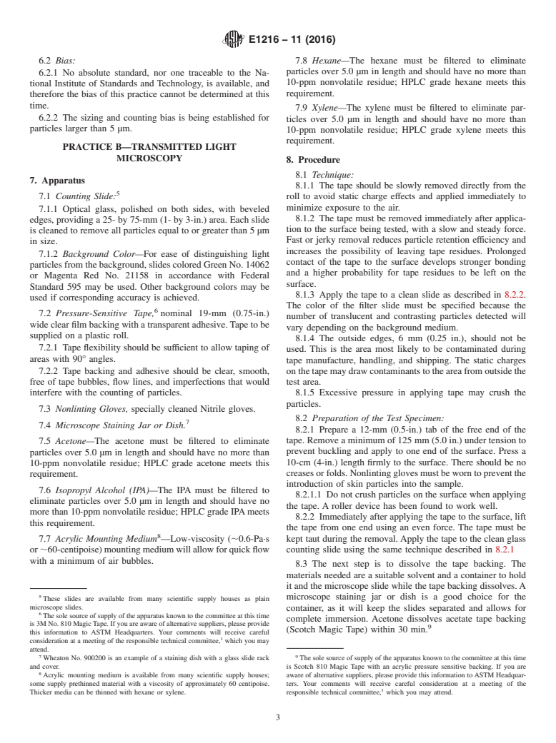
3.4 The selection of tape and the verification of its effect on 4.3 Nonlinting Gloves, specially cleaned Nitrile gloves.
the cleanliness of the hardware is very important. The tape
5. Procedure
adhesive should have sufficient cohesion to avoid transfer of
5.1 Technique:
the adhesive to the surface under test. The impact of adhesive
5.1.1 The tape shall be slowly removed directly from the
transfer should be evaluated by laboratory testing before using
roll to avoid static charge effects and applied immediately to
the tape on the hardware. Since potential for adhesive transfer
minimize exposure to the air.
exists, cleaning to remove any adhesive might be required. In
5.1.2 The tape must be removed immediately after applica-
addition, the tape should have low outgassing characteristics,
tion to the surface being tested with a slow and steady force.
and as a minimum, it should meet the requirements of less than
Fast or jerky removal reduces particle retention efficiency and
1.0 % total mass loss (TML) and 0.1 % collected volatile
increases the possibility of leaving tape residues. Prolonged
condensable materials (CVCM), as measured by Test Method
contactofthetapetothesurfacedevelopsstrongerbindingand
E595.
a higher probability for tape residues to be left on the surface.
3.5 Care should be exercised in deciding which surfaces
5.1.3 Apply the tape to a clean slide as described in 5.2.2.
should be tested by this practice. The tape can remove
The color of the filter slide must be specified because the
marginally adhering paint and coatings. Optical surfaces
number of translucent and contrasting particles detected will
should not be tested until verification has been made that the
vary depending on the background medium.
surface coating will not be damaged. Rough surface finishes
5.1.4 The outside edges, 6 mm (0.25 in.), shall not be used.
result in low removal efficiencies. Surface finishes up to
This is the area most likely to be contaminated during tape
approximately 3.20 µm (125 µin.) have been tested and found
manufacture, handling, and shipping. The static charges on the
to give satisfactory results.
tape may draw contaminants to the area from outside the test
3.6 This practice has been tested only on surfaces at room
area.
temperature. Evaluation of temperature effects must be con-
5.1.5 Excessive pressure in applying tape may crush the
ducted prior to using the test on surfaces other than room
particles.
temperature.
5.2 Preparation of the Test Specimen:
3.7 Only personnel experienced in microscopic particle-
5.2.1 Prepare a 12-mm (0.5-in.) tab of the free end of the
counting techniques should be used to count and size the
tape. Remove a minimum of 12 cm (5.0 in.) under tension to
particles.
prevent buckling and apply to one end of the surface. Press a
10-cm (4-in.) length firmly to the surface. There shall be no
PRACTICE A—TRANSMITTED LIGHT
creasesorfolds.Nonlintingglovesmustbeworntopreventthe
MICROSCOPY
introduction of skin particles into the sample.
5.2.1.1 Do not crush particles on the surface when applying
4. Apparatus
the tape. A roller device has been found to work well.
4.1 Counting Slide:
5.2.2 Immediately after applying the tape to the surface, lift
4.1.1 Optical glass, polished on both sides, with beveled
the tape from one end using an even force. The tape must be
edges and etched with low reflectance chrome to provide a
kept taut during the removal.Apply the tape to the etched side
7.62-by7.62-cm(3.0-by3.0-in.)areaconsistingof256(16by
of a clean glass counting slide using the same technique
16) individual numbered squares. Each square has 0.23 cm
described in 5.2.1.
(0.015 in. ) of area and is cleaned to remove all particles equal
5.3 Counting—Place the glass slide on a colored back-
to or greater than 5 µm in size.
ground stage of the microscope with the unetched side up. Size
4.1.2 Background Color—For ease of distinguishing light
and count the particulate contamination in accordance with
particles from the background, slides colored Green No. 14062
Test Methods F312. Squares falling within 6 mm (0.25 in.) of
or Magenta Red No. 21158 in accordance with Federal
the tape edge shall not be used. The total number of particles
Standard 595 may be used. Other background colors may be
should be sufficiently large to provide the statistical reliability
used if corresponding accuracy is achieved.
required by Test Methods F312.
4.2 Pressure-Sensitive Tape, nominal (50-mm) (2-in.) wide
5.4 Perform the blank analyses or tares to establish the
clear film backing with a transparent adhesive. Tape to be
background level of particles in the tape. The background
supplied on a plastic roll.
particle count of the blank shall be no more than 10 % of the
4.2.1 Tape flexibility should be sufficient to allow taping of
allowable value for the surface under test.
areas with 90° angles.
4.2.2 Tape backing and adhesive shall be clear, smooth, free
6. Precision and Bias
of tape bubbles, flow lines, and imperfections that would
6.1 Precision and bias are intended to be adequate for use as
interfere with the counting of particles.
a standard practice, or monitoring method.
6.1.1 Repeatability—Repeatability of the counting method
The sole source of supply of the apparatus known to the committee at this time
shall be defined in Test Methods F312.
is 3M No. 480 polyethylene tape with an acrylic pressure-sensitive backing. If you
6.1.2 Effectiveness—The minimum effectiveness of particle
are aware of alternative suppliers, please provide this information to ASTM
removal from smooth surfaces and angles down to 90° is 90 %
Headquarters.Your comments will receive careful consideration at a meeting of the
responsible technical committee, which you may attend. for particles larger than 5 µm.
E1216 − 11 (2016)
6.2 Bias: 7.8 Hexane—The hexane must be filtered to eliminate
particles over 5.0 µm in length and should have no more than
6.2.1 No absolute standard, nor one traceable to the Na-
10-ppm nonvolatile residue; HPLC grade hexane meets this
tional Institute of Standards and Technology, is available, and
requirement.
therefore the bias of this practice cannot be determined at this
time.
7.9 Xylene—The xylene must be filtered to eliminate par-
6.2.2 The sizing and counting bias is being established for
ticles over 5.0 µm in length and should have no more than
particles larger than 5 µm.
10-ppm nonvolatile residue; HPLC grade xylene meets this
requirement.
PRACTICE B—TRANSMITTED LIGHT
MICROSCOPY
8. Procedure
8.1 Technique:
7. Apparatus
8.1.1 The tape should be slowly removed directly from the
7.1 Counting Slide: roll to avoid static charge effects and applied immediately to
minimize exposure to the air.
7.1.1 Optical glass, polished on both sides, with beveled
8.1.2 The tape must be removed immediately after applica-
edges, providing a 25- by 75-mm (1- by 3-in.) area. Each slide
tion to the surface being tested, with a slow and steady force.
is cleaned to remove all particles equal to or greater than 5 µm
Fast or jerky removal reduces particle retention efficiency and
in size.
increases the possibility of leaving tape residues. Prolonged
7.1.2 Background Color—For ease of distinguishing light
contact of the tape to the surface develops stronger bonding
particles from the background, slides colored Green No. 14062
and a higher probability for tape residues to be left on the
or Magenta Red No. 21158 in accordance with Federal
surface.
Standard 595 may be used. Other background colors may be
8.1.3 Apply the tape to a clean slide as described in 8.2.2.
used if corresponding accuracy is achieved.
The color of the filter slide must be specified because the
7.2 Pressure-Sensitive Tape, nominal 19-mm (0.75-in.)
number of translucent and contrasting particles detected will
wide clear film backing with a transparent adhesive.Tape to be
vary depending on the background medium.
supplied on a plastic roll.
8.1.4 The outside edges, 6 mm (0.25 in.), should not be
7.2.1 Tape flexibility should be sufficient to allow taping of
used. This is the area most likely to be contaminated during
areas with 90° angles.
tape manufacture, handling, and shipping. The static charges
7.2.2 Tape backing and adhesive should be clear, smooth, onthetapemaydrawcontaminantstotheareafromoutsidethe
free of tape bubbles, flow lines, and imperfections that would test area.
interfere with the counting of particles. 8.1.5 Excessive pressure in applying tape may crush the
particles.
7.3 Nonlinting Gloves, specially cleaned Nitrile gloves.
8.2 Preparation of the Test Specimen:
7.4 Microscope Staining Jar or Dish.
8.2.1 Prepare a 12-mm (0.5-in.) tab of the free end of the
tape. Remove a minimum of 125 mm (5.0 in.) under tension to
7.5 Acetone—The acetone must be filtered to eliminate
prevent buckling and apply to one end of the surface. Press a
particles over 5.0 µm in length and should have no more than
10-cm (4-in.) length firmly to the surface. There should be no
10-ppm nonvolatile residue; HPLC grade acetone meets this
creasesorfolds.Nonlintingglovesmustbeworntopreventthe
requirement.
introduction of skin particles into the sample.
7.6 Isopropyl Alcohol (IPA)—The IPA must be filtered to
8.2.1.1 Do not crush particles on the surface when applying
eliminate particles over 5.0 µm in length and should have no
the tape. A roller device has been found to work well.
more than 10-ppm nonvolatile residue; HPLC grade IPAmeets
8.2.2 Immediately after applying the tape to the surface, lift
this requirement.
the tape from one end using an even force. The tape must be
7.7 Acrylic Mounting Medium —Low-viscosity (;0.6-Pa·s kept taut during the removal.Apply the tape to the clean glass
counting slide using the same technique described in 8.2.1
or ;60-centipoise)mountingmediumwillallowforquickflow
with a minimum of air bubbles.
8.3 The next step is to dissolve the tape backing. The
materials needed are a suitable solvent and a container to hold
it and the microscope slide while the tape backing dissolves.A
mi
...
This document is not an ASTM standard and is intended only to provide the user of an ASTM standard an indication of what changes have been made to the previous version. Because
it may not be technically possible to adequately depict all changes accurately, ASTM recommends that users consult prior editions as appropriate. In all cases only the current version
of the standard as published by ASTM is to be considered the official document.
Designation: E1216 − 11 E1216 − 11 (Reapproved 2016)
Standard Practice for
Sampling for Particulate Contamination by Tape Lift
This standard is issued under the fixed designation E1216; the number immediately following the designation indicates the year of
original adoption or, in the case of revision, the year of last revision. A number in parentheses indicates the year of last reapproval. A
superscript epsilon (´) indicates an editorial change since the last revision or reapproval.
1. Scope
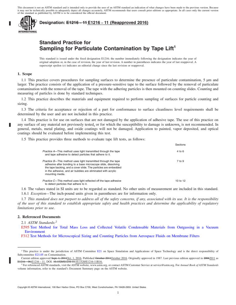
1.1 This practice covers procedures for sampling surfaces to determine the presence of particulate contamination, 5 μm and
larger. The practice consists of the application of a pressure-sensitive tape to the surface followed by the removal of particulate
contamination with the removal of the tape. The tape with the adhering particles is then mounted on counting slides. Counting and
measuring of particles is done by standard techniques.
1.2 This practice describes the materials and equipment required to perform sampling of surfaces for particle counting and
sizing.
1.3 The criteria for acceptance or rejection of a part for conformance to surface cleanliness level requirements shall be
determined by the user and are not included in this practice.
1.4 This practice is for use on surfaces that are not damaged by the application of adhesive tape. The use of this practice on
any surface of any material not previously tested, or for which the susceptibility to damage is unknown, is not recommended. In
general, metals, metal plating, and oxide coatings will not be damaged. Application to painted, vapor deposited, and optical
coatings should be evaluated before implementing this test.
1.5 This practice provides three methods to evaluate tape lift tests, as follows:
Sections
Practice A—This method uses light transmitted through the tape 4 to 6
and tape adhesive to detect particles that adhere to it.
Practice B—This method uses light transmitted through the tape 7 to 9
adhesive after bonding to a base microscope slide, dissolving
the tape backing, and a cover slide. The particles are embedded
in the adhesive, and air bubbles are eliminated with acrylic
mounting media.
Practice C—This method uses light reflected off the tape adhesive 10 to 12
to detect particles that adhere to it.
1.6 The values stated in SI units are to be regarded as standard. No other units of measurement are included in this standard.
1.6.1 Exception—The inch-pound units given in parentheses are for information only.
1.7 This standard does not purport to address all of the safety concerns, if any, associated with its use. It is the responsibility
of the user of this standard to establish appropriate safety and health practices and determine the applicability of regulatory
limitations prior to use.
2. Referenced Documents
2.1 ASTM Standards:
E595 Test Method for Total Mass Loss and Collected Volatile Condensable Materials from Outgassing in a Vacuum
Environment
F312 Test Methods for Microscopical Sizing and Counting Particles from Aerospace Fluids on Membrane Filters
This practice is under the jurisdiction of ASTM Committee E21 on Space Simulation and Applications of Space Technology and is the direct responsibility of
Subcommittee E21.05 on Contamination.
Current edition approved Sept. 1, 2011Oct. 1, 2016. Published October 2011October 2016. Originally approved in 1987. Last previous edition approved in 20062011 as
E1216 – 06.E1216 – 11. DOI: 10.1520/E1216-11.10.1520/E1216-11R16.
For referenced ASTM standards, visit the ASTM website, www.astm.org, or contact ASTM Customer Service at service@astm.org. For Annual Book of ASTM Standards
volume information, refer to the standard’s Document Summary page on the ASTM website.
Copyright © ASTM International, 100 Barr Harbor Drive, PO Box C700, West Conshohocken, PA 19428-2959. United States
E1216 − 11 (2016)
2.2 Federal Standard:
Federal Standard 595 Color
3. Significance and Use
3.1 The tape lift provides a rapid and simple technique for removing particles from a surface and determining their number and
size distribution.
3.2 By using statistically determined sample size and locations, an estimate of the surface cleanliness level of large areas can
be made. The user shall define the sampling plan.
3.3 The sampling plan shall consider the importance of surface geometry and surface orientation to gas flow, gravity,
obstructions, and previous history of hardware. These factors influence particle fallout and entrapment of particles on the surface.
The geometry of joints, recessed areas, fasteners, and the correspondence of particle-count data to area can be maintained.
3.4 The selection of tape and the verification of its effect on the cleanliness of the hardware is very important. The tape adhesive
should have sufficient cohesion to avoid transfer of the adhesive to the surface under test. The impact of adhesive transfer should
be evaluated by laboratory testing before using the tape on the hardware. Since potential for adhesive transfer exists, cleaning to
remove any adhesive might be required. In addition, the tape should have low outgassing characteristics, and as a minimum, it
should meet the requirements of less than 1.0 % total mass loss (TML) and 0.1 % collected volatile condensable materials
(CVCM), as measured by Test Method E595.
3.5 Care should be exercised in deciding which surfaces should be tested by this practice. The tape can remove marginally
adhering paint and coatings. Optical surfaces should not be tested until verification has been made that the surface coating will not
be damaged. Rough surface finishes result in low removal efficiencies. Surface finishes up to approximately 3.20 μm (125 μin.)
have been tested and found to give satisfactory results.
3.6 This practice has been tested only on surfaces at room temperature. Evaluation of temperature effects must be conducted
prior to using the test on surfaces other than room temperature.
3.7 Only personnel experienced in microscopic particle-counting techniques should be used to count and size the particles.
PRACTICE A—TRANSMITTED LIGHT MICROSCOPY
4. Apparatus
4.1 Counting Slide:
4.1.1 Optical glass, polished on both sides, with beveled edges and etched with low reflectance chrome to provide a 7.62- by
2 2
7.62-cm (3.0- by 3.0-in.) area consisting of 256 (16 by 16) individual numbered squares. Each square has 0.23 cm (0.015 in. )
of area and is cleaned to remove all particles equal to or greater than 5 μm in size.
4.1.2 Background Color—For ease of distinguishing light particles from the background, slides colored Green No. 14062 or
Magenta Red No. 21158 in accordance with Federal Standard 595 may be used. Other background colors may be used if
corresponding accuracy is achieved.
4.2 Pressure-Sensitive Tape, nominal nominal (50-mm) (2-in.) wide clear film backing with a transparent adhesive. Tape to be
supplied on a plastic roll.
4.2.1 Tape flexibility should be sufficient to allow taping of areas with 90° angles.
4.2.2 Tape backing and adhesive shall be clear, smooth, free of tape bubbles, flow lines, and imperfections that would interfere
with the counting of particles.
4.3 Nonlinting Gloves, specially cleaned Nitrile gloves.
5. Procedure
5.1 Technique:
5.1.1 The tape shall be slowly removed directly from the roll to avoid static charge effects and applied immediately to minimize
exposure to the air.
5.1.2 The tape must be removed immediately after application to the surface being tested with a slow and steady force. Fast or
jerky removal reduces particle retention efficiency and increases the possibility of leaving tape residues. Prolonged contact of the
tape to the surface develops stronger binding and a higher probability for tape residues to be left on the surface.
5.1.3 Apply the tape to a clean slide as described in 5.2.2. The color of the filter slide must be specified because the number
of translucent and contrasting particles detected will vary depending on the background medium.
Available from Standardization Documents Order Desk, DODSSP, Bldg. 4, Section D, 700 Robbins Ave., Philadelphia, PA 19111-5098, http://dodssp.daps.dla.mil.
The sole source of supply of the apparatus known to the committee at this time is 3M No. 480 polyethylene tape with an acrylic pressure-sensitive backing. If you are
aware of alternative suppliers, please provide this information to ASTM Headquarters. Your comments will receive careful consideration at a meeting of the responsible
technical committee, which you may attend.
E1216 − 11 (2016)
5.1.4 The outside edges, 6 mm (0.25 in.), shall not be used. This is the area most likely to be contaminated during tape
manufacture, handling, and shipping. The static charges on the tape may draw contaminants to the area from outside the test area.
5.1.5 Excessive pressure in applying tape may crush the particles.
5.2 Preparation of the Test Specimen:
5.2.1 Prepare a 12-mm (0.5-in.) tab of the free end of the tape. Remove a minimum of 12 cm (5.0 in.) under tension to prevent
buckling and apply to one end of the surface. Press a 10-cm (4-in.) length firmly to the surface. There shall be no creases or folds.
Nonlinting gloves must be worn to prevent the introduction of skin particles into the sample.
5.2.1.1 Do not crush particles on the surface when applying the tape. A roller device has been found to work well.
5.2.2 Immediately after applying the tape to the surface, lift the tape from one end using an even force. The tape must be kept
taut during the removal. Apply the tape to the etched side of a clean glass counting slide using the same technique described in
5.2.1.
5.3 Counting—Place the glass slide on a colored background stage of the microscope with the unetched side up. Size and count
the particulate contamination in accordance with Test Methods F312. Squares falling within 6 mm (0.25 in.) of the tape edge shall
not be used. The total number of particles should be sufficiently large to provide the statistical reliability required by Test Methods
F312.
5.4 Perform the blank analyses or tares to establish the background level of particles in the tape. The background particle count
of the blank shall be no more than 10 % of the allowable value for the surface under test.
6. Precision and Bias
6.1 Precision and bias are intended to be adequate for use as a standard practice, or monitoring method.
6.1.1 Repeatability—Repeatability of the counting method shall be defined in Test Methods F312.
6.1.2 Effectiveness—The minimum effectiveness of particle removal from smooth surfaces and angles down to 90° is 90 % for
particles larger than 5 μm.
6.2 Bias:
6.2.1 No absolute standard, nor one traceable to the National Institute of Standards and Technology, is available, and
therefore,therefore the bias of this practice cannot be determined at this time.
6.2.2 The sizing and counting bias is being established for particles larger than 5 μm.
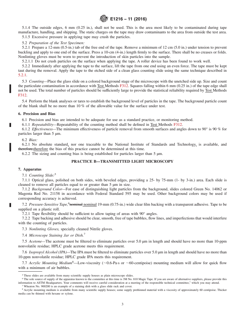
PRACTICE B—TRANSMITTED LIGHT MICROSCOPY
7. Apparatus
7.1 Counting Slide:
7.1.1 Optical glass, polished on both sides, with beveled edges, providing a 25- by 75-mm (1- by 3-in.) area. Each slide is
cleaned to remove all particles equal to or greater than 5 μm in size.
7.1.2 Background Color—For ease of distinguishing light particles from the background, slides colored Green No. 14062 or
Magenta Red No. 21158 in accordance with Federal Standard 595 may be used. Other background colors may be used if
corresponding accuracy is achieved.
7.2 Pressure-Sensitive Tape, nominal nominal 19-mm (0.75-in.) wide clear film backing with a transparent adhesive. Tape to be
supplied on a plastic roll.
7.2.1 Tape flexibility should be sufficient to allow taping of areas with 90° angles.
7.2.2 Tape backing and adhesive should be clear, smooth, free of tape bubbles, flow lines, and imperfections that would interfere
with the counting of particles.
7.3 Nonlinting Gloves, specially cleaned Nitrile gloves.
7.4 Microscope Staining Jar or Dish.
7.5 Acetone—The acetone must be filtered to eliminate particles over 5.0 μm in length and should have no more than 10-ppm
nonvolatile residue; HPLC grade acetone meets this requirement.
7.6 Isopropyl Alcohol (IPA)—The IPA must be filtered to eliminate particles over 5.0 μm in length and should have no more than
10-ppm nonvolatile residue; HPLC grade IPA meets this requirement.
7.7 Acrylic Mounting Medium —Low-viscosity (;0.6-Pa·s or ;60-centipoise) mounting medium will allow for quick flow
with a minimum of air bubbles.
These slides are available from many scientific supply houses as plain microscope slides.
The sole source of supply of the apparatus known to the committee at this time is 3M No. 810 Magic Tape. If you are aware of alternative suppliers, please provide this
information to ASTM Headquarters. Your comments will receive careful consideration at a meeting of the responsible technical committee, which you may attend.
Wheaton No. 900200 is an example of a staining dish with a glass slide rack and cover.
Acrylic mounting medium is available from many scientific supply houses; some supply prethinned material with a viscosity of approximately 60 centipoise. Thicker
media can be thinned with hexane or xylene.
E1216 − 11 (2016)
7.8 Hexane—The hexane must be filtered to eliminate particles over 5.0 μm in length and should have no more than 10-ppm
nonvolatile residue; HPLC grade hexane meets this requirement.
7.9 Xylene—The xylene must be filtered to eliminate particles over 5.0 μm in length and should have no more than 10-ppm
nonvolatile residue; HPLC grade xylene meets this requirement.
8. Procedure
8.1 Technique:
8.1.1 The tape should be slowly removed directly from the roll to avoid static charge effects and applied immediately to
minimize exposure to the air.
8.1.2 The tape must be removed immediately after application to the surface being tested, with a slow and steady force. Fast
or jerky removal reduces particle retention efficiency and increases the possibility of leaving tape residues. Prolonged contact of
the tape to the surface develops stronger bonding and a higher probability for tape residues to be left on the surface.
8.1.3 Apply the tape to a clean slide as described in 8.2.2. The color of the filter slide must be specified because the number
of translucent and contrasting particles detected will vary depending on the background medium.
8.1.4 The o
...
Questions, Comments and Discussion
Ask us and Technical Secretary will try to provide an answer. You can facilitate discussion about the standard in here.