


ASTM D6332-12(2017)
(Guide)Standard Guide for Testing Systems for Measuring Dynamic Responses of Carbon Monoxide Detectors to Gases and Vapors
Standard Guide for Testing Systems for Measuring Dynamic Responses of Carbon Monoxide Detectors to Gases and Vapors
SIGNIFICANCE AND USE
5.1 This guide provides information on testing systems and their components used for measuring responses of CO alarms or detectors subjected to gases, vapors, and their mixtures. Components of a testing system include a chamber, clean air supply module, humidification module, gas and vapor delivery module, and verification and control instrumentation.
5.2 The CO detector is tested by sequential exposure to CO and interference gases at the specified challenge concentrations. A properly functioning alarm/detector will sound upon sufficient exposure to CO but will not sound upon any exposure to interference gases consistent with applicable standards (for example, IAS 6-96 (1),5 L 2034).
SCOPE
1.1 This guide describes testing systems used for measuring responses of carbon monoxide (CO) alarms or detectors subjected to gases, vapors, and their mixtures.
1.2 The systems are used to evaluate responses of CO detectors to various CO concentrations, to verify that the detectors alarm at certain specified CO concentrations, and to verify that CO detectors do not alarm at certain other specified CO concentrations.
1.3 The systems are used for evaluating CO detector responses to gases and vapors that may interfere with the ability of detectors to respond to CO.
1.4 Major components of such a testing system include a chamber, clean air supply module, humidification module, gas and vapor delivery module, and verification and control instrumentation.
1.5 For each component, this guide provides a comparison of different approaches and discusses their advantages and disadvantages.
1.6 The guide also presents recommendations for a minimum configuration of a testing system.
1.7 Units—The values stated in SI units are to be regarded as standard. No other units of measurement are included in this standard.
1.8 This standard does not purport to address all of the safety concerns, if any, associated with its use. It is the responsibility of the user of this standard to establish appropriate safety, health, and environmental practices and determine the applicability of regulatory limitations prior to use. For more specific safety precautionary information, see 6.2.
1.9 This international standard was developed in accordance with internationally recognized principles on standardization established in the Decision on Principles for the Development of International Standards, Guides and Recommendations issued by the World Trade Organization Technical Barriers to Trade (TBT) Committee.
General Information
Buy Standard
Standards Content (Sample)
NOTICE: This standard has either been superseded and replaced by a new version or withdrawn.
Contact ASTM International (www.astm.org) for the latest information
Designation: D6332 − 12 (Reapproved 2017)
Standard Guide for
Testing Systems for Measuring Dynamic Responses of
Carbon Monoxide Detectors to Gases and Vapors
This standard is issued under the fixed designation D6332; the number immediately following the designation indicates the year of
original adoption or, in the case of revision, the year of last revision. A number in parentheses indicates the year of last reapproval. A
superscript epsilon (´) indicates an editorial change since the last revision or reapproval.
1. Scope mendations issued by the World Trade Organization Technical
Barriers to Trade (TBT) Committee.
1.1 This guide describes testing systems used for measuring
responses of carbon monoxide (CO) alarms or detectors
2. Referenced Documents
subjected to gases, vapors, and their mixtures.
2.1 ASTM Standards:
1.2 The systems are used to evaluate responses of CO
D1193 Specification for Reagent Water
detectors to various CO concentrations, to verify that the
D1356 Terminology Relating to Sampling and Analysis of
detectors alarm at certain specified CO concentrations, and to
Atmospheres
verify that CO detectors do not alarm at certain other specified
D1945 Test Method for Analysis of Natural Gas by Gas
CO concentrations.
Chromatography
1.3 The systems are used for evaluating CO detector re-
D3162 Test Method for Carbon Monoxide in the Atmo-
sponses to gases and vapors that may interfere with the ability
sphere (Continuous Measurement by Nondispersive Infra-
of detectors to respond to CO.
red Spectrometry)
D3195 Practice for Rotameter Calibration
1.4 Major components of such a testing system include a
D3249 Practice for General Ambient Air Analyzer Proce-
chamber, clean air supply module, humidification module, gas
dures
and vapor delivery module, and verification and control instru-
D3687 Practice for Analysis of Organic Compound Vapors
mentation.
Collected by the Activated Charcoal Tube Adsorption
1.5 For each component, this guide provides a comparison
Method
of different approaches and discusses their advantages and
2.2 Other Standards:
disadvantages.
UL 2034 Single and Multiple Station Carbon Monoxide
1.6 The guide also presents recommendations for a mini-
Alarms
mum configuration of a testing system.
CFR 1910.1450 Occupational Exposure to Hazardous
Chemicals in Laboratories
1.7 Units—The values stated in SI units are to be regarded
as standard. No other units of measurement are included in this
3. Terminology
standard.
3.1 Definitions—For definitions of terms used in this guide,
1.8 This standard does not purport to address all of the
refer to Terminology D1356.
safety concerns, if any, associated with its use. It is the
responsibility of the user of this standard to establish appro-
3.2 Definitions of Terms Specific to This Standard:
priate safety, health, and environmental practices and deter-
3.2.1 air change rate, n—the volume of clean, humidified
mine the applicability of regulatory limitations prior to use.
airpluscontaminantsthatentersthechamberin1h,dividedby
For more specific safety precautionary information, see 6.2.
the internal volume of the chamber, expressed as air changes
–1
1.9 This international standard was developed in accor-
per hour (h ).
dance with internationally recognized principles on standard-
ization established in the Decision on Principles for the
For referenced ASTM standards, visit the ASTM website, www.astm.org, or
Development of International Standards, Guides and Recom-
contact ASTM Customer Service at service@astm.org. For Annual Book of ASTM
Standards volume information, refer to the standard’s Document Summary page on
the ASTM website.
1 3
This guide is under the jurisdiction of ASTM Committee D22 on Air Quality Available from Underwriters Laboratories (UL), 2600 N.W. Lake Rd., Camas,
and is the direct responsibility of Subcommittee D22.05 on Indoor Air. WA 98607-8542, http://www.ul.com.
Current edition approved Oct. 1, 2017. Published October 2017. Originally Available from U.S. Government Printing Office, Superintendent of
approved in 1998. Last previous edition approved in 2012 as D6332 – 12. DOI: Documents, 732 N. Capitol St., NW, Washington, DC 20401-0001, http://
10.1520/D6332-12R17. www.access.gpo.gov.
Copyright © ASTM International, 100 Barr Harbor Drive, PO Box C700, West Conshohocken, PA 19428-2959. United States
D6332 − 12 (2017)
3.2.2 chamber, n—an enclosed test volume composed of 6.2 Hazards—In a dynamic chamber, the air exiting cham-
chemicallyinertmaterialssuppliedwithamixtureofair,gases, ber will contain CO and interference gases or vapors that may
or vapors, or combination thereof, having known composi- be toxic. To avoid undue exposures of toxic gases and vapors
tions. to occupants of the laboratory (where the chamber is located),
the chamber should be properly vented to outside with an
3.2.3 CO alarm/detector, n—an alarm device consisting of
appropriate stack. For a static chamber, exposures to test gases
an assembly of electrical and mechanical components with
should be avoided in operating (for example, opening) the
chemical, electrochemical, solid-state electronic, or other types
chamber.
of sensors to detect the presence of CO gas in specified ranges
of concentrations.
6.3 Size of the Chamber—The chamber size can be large
3.2.4 sensor, n—the component included in the CO alarm/ (that is, room-size) or small and depends on the number of
detector that senses CO gas.
detectors to be tested. Detectors should be placed on a wire
rackorsimilarsupportingstructure.Detectorsshouldbeplaced
4. Summary of Guide
at least 0.10-m away from the chamber walls. If multiple
4.1 This guide describes components of systems for testing
detectors are undergoing simultaneous testing, they should be
CO detectors with mixtures of air and CO at different concen-
spaced at least 0.051 m from each other. The chamber size
trations of CO. The systems are also used for evaluating the
required by UL 2034 is a 0.91 by 0.91 by 0.91-m box, which
responses of CO detectors to mixtures of air and various gases
has been found to be practical for testing several detectors at a
or vapors, or both. Such systems require clean air with a
time.
preselected level of relative humidity supplied to an environ-
6.4 Material of Construction—Thechambershouldbemade
mental chamber. Gases and vapors are introduced in the clean
of relatively inert materials, such as glass, stainless steel, or
air supply or placed directly in the chamber to achieve desired
certain types of polymers/plastics. Materials, such as wood or
chamber concentration. The components of such systems
gypsum board, may not be appropriate because of their
include devices or modules for supplying pure air, humidifying
absorption, adsorption, and leakage characteristics. Joints
air, supplying gases or vapors, or both, to be tested, reference
should be well-sealed using inert caulking/sealing materials.
instruments for verifying concentrations of gases and vapors,
Gaskets should be used around doors and other closable
and a chamber for placing and exposing CO detectors. The
openings to achieve a good seal when closed.
guide describes various options for each component: chamber
(Section 6), clean air supply module (Section 7), humidifica-
6.5 Air Change Rate—The air change rate of a dynamic
–1
tion module (Section 8), gas/vapor delivery module (Section
chamber should be sufficient (for example, 1 h or higher) to
9), and verification and control module (Section10).The guide
overcome loss of chamber air through leakage and the deple-
further provides recommendations on a minimum configura-
tion of test gases and vapors due to factors, such as consump-
tion for the testing system (Section 11) and reporting results
tion through a chemical reaction or deposition.
(Section 12).
6.6 Mixing—To provide a uniform concentration for testing,
5. Significance and Use
the chamber air should be well mixed. With an adequate air
–1
change rate (for example, 1 h or higher), mixing can be
5.1 This guide provides information on testing systems and
achieved through proper placement and design of inlet and
their components used for measuring responses of CO alarms
outlet ports.The design and placement should be such that any
or detectors subjected to gases, vapors, and their mixtures.
short-circuiting of flow from inlet to outlet ports is avoided.A
Components of a testing system include a chamber, clean air
better alternative to promote mixing is to use a fan that is
supply module, humidification module, gas and vapor delivery
appropriately sized for the chamber volume. For example,
module, and verification and control instrumentation.
mixing within a large chamber having 23-m volume can be
5.2 The CO detector is tested by sequential exposure to CO
achieved by an 0.38-m /s fan. Ideally, the fan should be
and interference gases at the specified challenge concentra-
mounted on a shaft through the chamber wall, and the fan
tions. A properly functioning alarm/detector will sound upon
motor should be external to the chamber to prevent contami-
sufficientexposuretoCObutwillnotsounduponanyexposure
nation and heat load in the chamber. If a fan is used, the sensor
to interference gases consistent with applicable standards (for
ports should be shielded from direct air impingement. In
example, IAS 6-96 (1), L 2034).
addition to providing a uniform air concentration, the combi-
nation of air change rate and mixing should be such that it
6. Chamber
provides sufficient face velocity (for example, over 1 m/s) at
6.1 Types of Chamber—There are two types of chambers—
sensor head(s) through the detector housing.
static and dynamic. In a static chamber, air and known
quantities of gases are introduced and then the chamber is 6.7 The chamber should be able to provide accurate control
sealed. In a dynamic chamber, a characterized air-gas mixture of temperature and relative humidity at ambient pressure as
is continually introduced at a rate sufficient to maintain target indicated in Table 1. The chamber should be airtight to
concentrations. minimize any leakage of ambient air into or chamber air out of
the system. The environmental conditions cited in Table 1
cover ranges specified in standards listed in 2.2 and in the
The boldface numbers in parentheses refer to references at the end of this
standard. literature (1). Also, UL 2034 prescribes certain time period(s)
D6332 − 12 (2017)
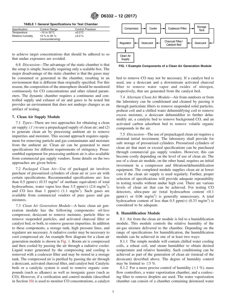
TABLE 1 General Specifications for Test Chamber
Specification Control Range Control Precision
Temperature –10 to 52°C ±0.5°C
Relative humidity 15 % to 95 % ±5.0 %
(noncondensing)
to achieve target concentrations that should be adhered to so
that undue exposures are avoided.
6.8 Discussion—The advantage of the static chamber is that
FIG. 1 Example Components of a Clean Air Generation Module
thesetupissimple,basicallyrequiringonlyasealablebox.The
major disadvantage of the static chamber is that the gases may
be consumed or generated in the chamber, resulting in an bed to remove CO may not be necessary. If a catalyst bed is
environment that is different than originally specified. For this used, use a desiccant and a downstream activated charcoal
reason,thecompositionoftheatmosphereshouldbemonitored filter to remove water vapor and oxides of nitrogen,
continuously for CO concentrations and other related param- respectively, that are generated from the catalyst bed.
eters. The dynamic chamber requires a continuous and con-
7.4 Alternate Clean Air Module—Airfromoutdoorsorfrom
trolled supply and exhaust of air and gases to be tested but
the laboratory can be conditioned and cleaned by passing it
provides an environment that does not undergo changes as an
through particulate filters to remove suspended solid particles,
artifact of testing.
preheat coil and a chilled water dehumidifying coil to remove
excess moisture, a desiccant dehumidifier to further dehu-
7. Clean Air Supply Module
midify air, a catalytic bed to remove background CO, and an
7.1 Types—There are two approaches for obtaining a clean
activated carbon adsorbent bed to remove volatile organic
airsupply:(1)touseaprepackagedsupplyofcleanair;and(2)
compounds in the air.
to generate clean air by processing ambient air to remove
7.5 Discussion—Theuseofprepackagedcleanairrequiresa
impurities and moisture. This second approach requires equip-
minimal initial investment. The laboratory shall provide for
ment for removing particle and gas contaminants and moisture
safe storage of pressurized cylinders. Pressurized cylinders of
from the ambient air. Clean air can be generated to meet
clean air that meet or exceed specifications can be purchased
specifications for different requirements of stringency. Preas-
through commercial gas supply vendors. However, this can
sembled equipment for processing ambient air is also available
become costly depending on the level of use of clean air. The
from commercial gas supply vendors. Some details on the two
use of a clean air module, on the other hand, requires an initial
approaches are given below.
investment in a compressor and filtration/dehumidification
7.2 Packaged Clean Air—Use of packaged air involves
equipment. The completed module supplies clean air at lower
purchase of pressurized cylinders of clean air or zero air with
cost if the clean air supply is used regularly. Further, proper
certain specifications. Recommended specifications are: less
selection of specifications will provide adequate repeatability
than 0.5 ppm(v) (0.33 mg/m of methane equivalent) of total
in testing results without undue high cost. There are various
hydrocarbons, water vapor less than 3.5 ppm(v) (2.6 mg/m ),
levels of clean air that can be achieved. For testing CO
and CO less than 1 ppm(v) (1.1 mg/m ). Such gases are
detectors, ultra-pure air (total hydrocarbon content <0.1
available from commercial vendors of pure gases and gas
ppm(v) or 0.06 mg/m ) is generally unnecessary. A total
mixtures.
hydrocarbon content of less than 0.5 ppm(v) (0.33 mg/m)is
considered to be adequate.
7.3 Clean Air Generation Module—A basic clean air gen-
eration module has the following components: oil-less
8. Humidification Module
compressor, desiccant to remove moisture, particle filter to
remove suspended particles, and activated charcoal filter or 8.1 Air from the clean air module is fed to a humidification
catalyst bed, or both, to remove gaseous impurities. In addition module. This module controls the relative humidity of the
to these components, a storage tank, high pressure lines, and air-gas mixture delivered to the chamber. Depending on the
regulator are necessary.Aradiative cooler may be necessary to range of specifications for humidification, the humidification
cool compressed air
...
This document is not an ASTM standard and is intended only to provide the user of an ASTM standard an indication of what changes have been made to the previous version. Because
it may not be technically possible to adequately depict all changes accurately, ASTM recommends that users consult prior editions as appropriate. In all cases only the current version
of the standard as published by ASTM is to be considered the official document.
Designation: D6332 − 12 D6332 − 12 (Reapproved 2017)
Standard Guide for
Testing Systems for Measuring Dynamic Responses of
Carbon Monoxide Detectors to Gases and Vapors
This standard is issued under the fixed designation D6332; the number immediately following the designation indicates the year of
original adoption or, in the case of revision, the year of last revision. A number in parentheses indicates the year of last reapproval. A
superscript epsilon (´) indicates an editorial change since the last revision or reapproval.
1. Scope
1.1 This guide describes testing systems used for measuring responses of carbon monoxide (CO) alarms or detectors subjected
to gases, vapors, and their mixtures.
1.2 The systems are used to evaluate responses of CO detectors to various CO concentrations, to verify that the detectors alarm
at certain specified CO concentrations, and to verify that CO detectors do not alarm at certain other specified CO concentrations.
1.3 The systems are used for evaluating CO detector responses to gases and vapors that may interfere with the ability of
detectors to respond to CO.
1.4 Major components of such a testing system include a chamber, clean air supply module, humidification module, gas and
vapor delivery module, and verification and control instrumentation.
1.5 For each component, this guide provides a comparison of different approaches and discusses their advantages and
disadvantages.
1.6 The guide also presents recommendations for a minimum configuration of a testing system.
1.7 Units—The values stated in SI units are to be regarded as standard. No other units of measurement are included in this
standard.
1.8 This guidestandard does not purport to address all of the safety concerns, if any, associated with its use. It is the
responsibility of the user of this standard to establish appropriate safety safety, health, and healthenvironmental practices and
determine the applicability of regulatory limitations prior to use. For more specific safety precautionary information, see 6.2.
1.9 This international standard was developed in accordance with internationally recognized principles on standardization
established in the Decision on Principles for the Development of International Standards, Guides and Recommendations issued
by the World Trade Organization Technical Barriers to Trade (TBT) Committee.
2. Referenced Documents
2.1 ASTM Standards:
D1193 Specification for Reagent Water
D1356 Terminology Relating to Sampling and Analysis of Atmospheres
D1945 Test Method for Analysis of Natural Gas by Gas Chromatography
D3162 Test Method for Carbon Monoxide in the Atmosphere (Continuous Measurement by Nondispersive Infrared Spectrom-
etry)
D3195 Practice for Rotameter Calibration
D3249 Practice for General Ambient Air Analyzer Procedures
D3687 Practice for Analysis of Organic Compound Vapors Collected by the Activated Charcoal Tube Adsorption Method
This guide is under the jurisdiction of ASTM Committee D22 on Air Quality and is the direct responsibility of Subcommittee D22.05 on Indoor Air.
Current edition approved April 1, 2012Oct. 1, 2017. Published May 2012October 2017. Originally approved in 1998. Last previous edition approved in 20052012 as
D6332 – 99 (2005).D6332 – 12. DOI: 10.1520/D6332-12.10.1520/D6332-12R17.
For referenced ASTM standards, visit the ASTM website, www.astm.org, or contact ASTM Customer Service at service@astm.org. For Annual Book of ASTM Standards
volume information, refer to the standard’s Document Summary page on the ASTM website.
Copyright © ASTM International, 100 Barr Harbor Drive, PO Box C700, West Conshohocken, PA 19428-2959. United States
D6332 − 12 (2017)
2.2 Other Standards:
UL 2034 Single and Multiple Station Carbon Monoxide Alarms
CFR 1910.1450 Occupational Exposure to Hazardous Chemicals in Laboratories
3. Terminology
3.1 Definitions—For definitions of terms used in this guide, refer to Terminology D1356.
3.2 Definitions of Terms Specific to This Standard:
3.2.1 air change rate—rate, n—the volume of clean, humidified air plus contaminants that enters the chamber in 1 h, divided
–1
by the internal volume of the chamber, expressed as air changes per hour (h ).
3.2.2 chamber—chamber, n—an enclosed test volume composed of chemically inert materials supplied with a mixture of air,
gases, or vapors, or combination thereof, having known compositions.
3.2.3 CO alarm/detector—alarm/detector, n—an alarm device consisting of an assembly of electrical and mechanical
components with chemical, electrochemical, solid-state electronic, or other types of sensors to detect the presence of CO gas in
specified ranges of concentrations.
3.2.4 sensor—sensor, n—the component included in the CO alarm/detector that senses CO gas.
4. Summary of Guide
4.1 This guide describes components of systems for testing CO detectors with mixtures of air and CO at different concentrations
of CO. The systems are also used for evaluating the responses of CO detectors to mixtures of air and various gases or vapors, or
both. Such systems require clean air with a preselected level of relative humidity supplied to an environmental chamber. Gases
and vapors are introduced in the clean air supply or placed directly in the chamber to achieve desired chamber concentration. The
components of such systems include devices or modules for supplying pure air, humidifying air, supplying gases or vapors, or both,
to be tested, reference instruments for verifying concentrations of gases and vapors, and a chamber for placing and exposing CO
detectors. The guide describes various options for each component: chamber (Section 6), clean air supply module (Section 7),
humidification module (Section 8), gas/vapor delivery module (Section 9), and verification and control module (Section 10). The
guide further provides recommendations on a minimum configuration for the testing system (Section 11) and reporting results
(Section 12).
5. Significance and Use
5.1 This guide provides information on testing systems and their components used for measuring responses of CO alarms or
detectors subjected to gases, vapors, and their mixtures. Components of a testing system include a chamber, clean air supply
module, humidification module, gas and vapor delivery module, and verification and control instrumentation.
5.2 The CO detector is tested by sequential exposure to CO and interference gases at the specified challenge concentrations. A
properly functioning alarm/detector will sound upon sufficient exposure to CO but will not sound upon any exposure to
interference gases consistent with applicable standards (for example, IAS 6-96 (1), L 2034).
6. Chamber
6.1 Types of Chamber—There are two types of chambers—static and dynamic. In a static chamber, air and known quantities
of gases are introduced and then the chamber is sealed. In a dynamic chamber, a characterized air-gas mixture is continually
introduced at a rate sufficient to maintain target concentrations.
6.2 Hazards—In a dynamic chamber, the air exiting chamber will contain CO and interference gases or vapors that may be toxic.
To avoid undue exposures of toxic gases and vapors to occupants of the laboratory (where the chamber is located), the chamber
should be properly vented to outside with an appropriate stack. For a static chamber, exposures to test gases should be avoided
in operating (for example, opening) the chamber.
6.3 Size of the Chamber—The chamber size can be large (that is, room-size) or small and depends on the number of detectors
to be tested. Detectors should be placed on a wire rack or similar supporting structure. Detectors should be placed at least 0.10-m
away from the chamber walls. If multiple detectors are undergoing simultaneous testing, they should be spaced at least 0.051 m
from each other. The chamber size required by UL 2034 is a 0.91 by 0.91 by 0.91-m box, which has been found to be practical
for testing several detectors at a time.
6.4 Material of Construction—The chamber should be made of relatively inert materials, such as glass, stainless steel, or certain
types of polymers/plastics. Materials, such as wood or gypsum board, may not be appropriate because of their absorption,
Available from Underwriters Laboratories (UL), 2600 N.W. Lake Rd., Camas, WA 98607-8542, http://www.ul.com.
Available from U.S. Government Printing Office, Superintendent of Documents, 732 N. Capitol St., NW, Mail Stop: SDE, Washington, DC 20401,20401-0001,
http://www.access.gpo.gov.
The boldface numbers in parentheses refer to references at the end of this standard.
D6332 − 12 (2017)
adsorption, and leakage characteristics. Joints should be well-sealed using inert caulking/sealing materials. Gaskets should be used
around doors and other closable openings to achieve a good seal when closed.
–1
6.5 Air Change Rate—The air change rate of a dynamic chamber should be sufficient (for example, 1 h or higher) to overcome
loss of chamber air through leakage and the depletion of test gases and vapors due to factors, such as consumption through a
chemical reaction or deposition.
6.6 Mixing—To provide a uniform concentration for testing, the chamber air should be well mixed. With an adequate air change
–1
rate (for example, 1 h or higher), mixing can be achieved through proper placement and design of inlet and outlet ports. The
design and placement should be such that any short-circuiting of flow from inlet to outlet ports is avoided. A better alternative to
promote mixing is to use a fan that is appropriately sized for the chamber volume. For example, mixing within a large chamber
3 3
having 23-m volume can be achieved by an 0.38-m /s fan. Ideally, the fan should be mounted on a shaft through the chamber wall,
and the fan motor should be external to the chamber to prevent contamination and heat load in the chamber. If a fan is used, the
sensor ports should be shielded from direct air impingement. In addition to providing a uniform air concentration, the combination
of air change rate and mixing should be such that it provides sufficient face velocity (for example, over 1 m/s) at sensor head(s)
through the detector housing.
6.7 The chamber should be able to provide accurate control of temperature and relative humidity at ambient pressure as
indicated in Table 1. The chamber should be airtight to minimize any leakage of ambient air into or chamber air out of the system.
The environmental conditions cited in Table 1 cover ranges specified in standards listed in 2.2 and in the literature (1). Also, UL
2034 prescribes certain time period(s) to achieve target concentrations that should be adhered to so that undue exposures are
avoided.
6.8 Discussion—The advantage of the static chamber is that the setup is simple, basically requiring only a sealable box. The
major disadvantage of the static chamber is that the gases may be consumed or generated in the chamber, resulting in an
environment that is different than originally specified. For this reason, the composition of the atmosphere should be monitored
continuously for CO concentrations and other related parameters. The dynamic chamber requires a continuous and controlled
supply and exhaust of air and gases to be tested but provides an environment that does not undergo changes as an artifact of testing.
7. Clean Air Supply Module
7.1 Types—There are two approaches for obtaining a clean air supply: (1 ) to use a prepackaged supply of clean air; and (2)
to generate clean air by processing ambient air to remove impurities and moisture. This second approach requires equipment for
removing particle and gas contaminants and moisture from the ambient air. Clean air can be generated to meet specifications for
different requirements of stringency. Preassembled equipment for processing ambient air is also available from commercial gas
supply vendors. Some details on the two approaches are given below.
7.2 Packaged Clean Air—Use of packaged air involves purchase of pressurized cylinders of clean air or zero air with certain
specifications. Recommended specifications are: less than 0.5 ppm(v) (0.33 mg/m of methane equivalent) of total hydrocarbons,
3 3
water vapor less than 3.5 ppm(v) (2.6 mg/m ), and CO less than 1 ppm(v) (1.1 mg/m ). Such gases are available from commercial
vendors of pure gases and gas mixtures.
7.3 Clean Air Generation Module—A basic clean air generation module has the following components: oil-less compressor,
desiccant to remove moisture, particle filter to remove suspended particles, and activated charcoal filter or catalyst bed, or both,
to remove gaseous impurities. In addition to these components, a storage tank, high pressure lines, and regulator are necessary. A
radiative cooler may be necessary to cool compressed air. An example flow diagram for a clean air generation module is shown
in Fig. 1. Room air is compressed and then cooled by passing the air through a radiative cooler. Liquid water generated by the
compressing and cooling is removed with a coalescer filter and may be stored in a storage tank. The compressed air is purified
by passing the air through a desiccant, activated charcoal filter, and catalyst bed. Catalytic beds or a catalytic system is used to
remove organic compounds (such as alkanes) as well as inorganic gases (such as CO). However, if a verification and control
module (described in Section 10) is used to monitor CO concentrations, a catalyst bed to remove CO may not be necessary. If a
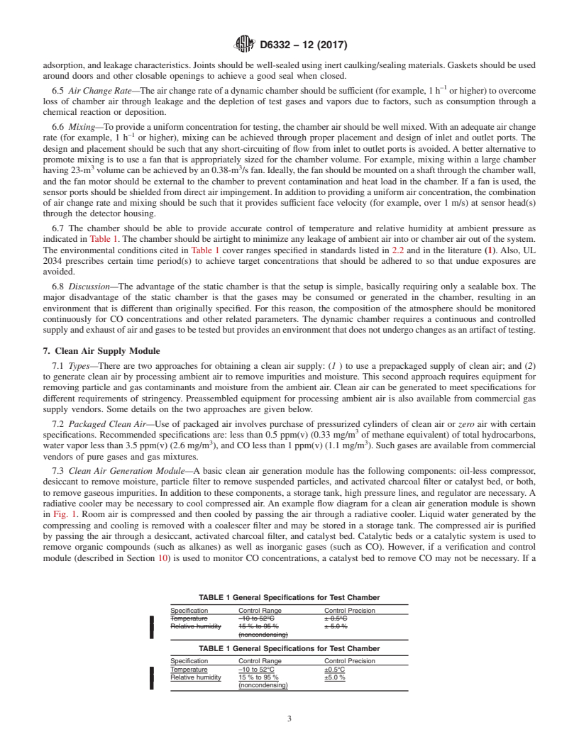
TABLE 1 General Specifications for Test Chamber
Specification Control Range Control Precision
Temperature –10 to 52°C ± 0.5°C
Relative humidity 15 % to 95 % ± 5.0 %
(noncondensing)
TABLE 1 General Specifications for Test Chamber
Specification Control Range Control Precision
Temperature –10 to 52°C ±0.5°C
Relative humidity 15 % to 95 % ±5.0 %
(noncondensing)
D6332 − 12 (2017)
FIG. 1 Example Components of a Clean Air Generation Module
catalyst bed is used, use a desiccant and a downstream activated charcoal filter to remove water vapor and oxides of nitrogen,
respectively, that are generated from the catalyst bed.
7.4 Alternate Clean Air Module—Air from outdoors or from the laboratory can be conditioned and cleaned by passing it through
particulate filters to remove suspended solid particles, preheat coil and a chilled water dehumidifying coil to remove excess
moisture, a desiccant dehumidifier to further dehumidify air, a catalytic be
...
Questions, Comments and Discussion
Ask us and Technical Secretary will try to provide an answer. You can facilitate discussion about the standard in here.