


ASTM D1210-05(2014)
(Test Method)Standard Test Method for Fineness of Dispersion of Pigment-Vehicle Systems by Hegman-Type Gage
Standard Test Method for Fineness of Dispersion of Pigment-Vehicle Systems by Hegman-Type Gage
SIGNIFICANCE AND USE
4.1 In making pigmented products, the pigment is usually dispersed in a portion of the vehicle in some sort of mill. At this stage, it is necessary to be able to judge if the pigment agglomerates have been sufficiently broken up so as not to interfere with the smoothness of the finished coating film. This test method describes a way of making this judgment.
SCOPE
1.1 This test method covers measurement of the degree of dispersion (commonly referred to as “fineness of grind”) of the pigment in a pigment-vehicle system such as liquid coatings and their intermediates. It may also be used to assess the inclusion of particulates by a cleanliness (or texture) rating.
1.2 The values stated in SI units are to be regarded as the standard. The values given in parentheses are for information only.
1.3 This standard does not purport to address all of the safety concerns, if any, associated with its use. It is the responsibility of the user of this standard to establish appropriate safety and health practices and determine the applicability of regulatory limitations prior to use.
General Information
Buy Standard
Standards Content (Sample)
NOTICE: This standard has either been superseded and replaced by a new version or withdrawn.
Contact ASTM International (www.astm.org) for the latest information
Designation: D1210 − 05 (Reapproved 2014)
Standard Test Method for
Fineness of Dispersion of Pigment-Vehicle Systems by
Hegman-Type Gage
This standard is issued under the fixed designation D1210; the number immediately following the designation indicates the year of
original adoption or, in the case of revision, the year of last revision. A number in parentheses indicates the year of last reapproval. A
superscript epsilon (´) indicates an editorial change since the last revision or reapproval.
This standard has been approved for use by agencies of the U.S. Department of Defense.
2 2
1. Scope this gage, each of 6.5 cm (1 in. ) area, and of two different
depths. A count is made of the particles deposited in the two
1.1 This test method covers measurement of the degree of
delimited areas, and cleanliness (texture) reading is deter-
dispersion (commonly referred to as “fineness of grind”) of the
mined.
pigment in a pigment-vehicle system such as liquid coatings
and their intermediates. It may also be used to assess the
4. Significance and Use
inclusion of particulates by a cleanliness (or texture) rating.
4.1 In making pigmented products, the pigment is usually
1.2 The values stated in SI units are to be regarded as the
dispersedinaportionofthevehicleinsomesortofmill.Atthis
standard. The values given in parentheses are for information
stage, it is necessary to be able to judge if the pigment
only.
agglomerates have been sufficiently broken up so as not to
1.3 This standard does not purport to address all of the
interfere with the smoothness of the finished coating film. This
safety concerns, if any, associated with its use. It is the
test method describes a way of making this judgment.
responsibility of the user of this standard to establish appro-
5. Apparatus
priate safety and health practices and determine the applica-
bility of regulatory limitations prior to use.
5.1 Tapered Gage—A hardened steel, stainless steel, or
chrome-plated steel block (Fig. 1) approximately 170 mm (6.7
2. Referenced Documents
in.) in length, and 15 mm (0.6 in.) in thickness.The top surface
of the block shall be ground smooth and planar and shall
2.1 ASTM Standards:
D1316 Test Method for Fineness of Grind of Printing Inks contain one or two paths 127 mm (5 in.) in calibrated length.
The path shall be tapered uniformly in depth lengthwise from
By the NPIRI Grindometer
about 4 mils (100 µm) at 10 mm from one end to zero depth at
3. Summary of Test Method
the other with intermediate calibrations in accordance with the
depth at those points. Preferred calibrations are Hegman units
3.1 Tapered Gage—The product is spread by means of a
and micrometers (Note 1). Three path widths are covered by
scraper in a machined tapered path.At some point in this path,
this test method:
particlesoragglomerates,orboth,willbecomevisible.Adirect
5.1.1 Two Parallel Paths, each 12.5-mm (0.5-in.) wide and
reading from the graduated scale is then made at the point
spaced 0.5-in. apart centered in a block 65-mm (2.5-in.) wide
where the particles form a definite pattern. When the single
(see Fig. 1).
path gage is used it is also possible to rate “cleanliness” (see
5.1.2 One Path, 50 mm (2 in.) in width centered in a block
6.2).
90-mm (3.5-in.) wide (see Fig. 1).
3.2 Stepped Gage—The product is spread by means of a
5.1.3 One Path, 25 mm (1 in.) in width centered in a block
scraper on a stepped gage. There are 2 delimited sections on
65-mm (2.5-in.) wide (see Fig. 1a).
NOTE1—Severalarbitraryscalesandmodificationsofthegageareused
1 by industry. In order that readings obtained with these arbitrary scales and
This test method is under the jurisdiction of ASTM Committee D01 on Paint
modifications can be reported in the preferred units, the approximate
and Related Coatings, Materials, andApplications and is the direct responsibility of
relationship of these scales to gage depth is shown in the following
Subcommittee D01.24 on Physical Properties of Liquid Paints and Paint Materials.
example:
Current edition approved Dec. 1, 2014. Published December 2014. Originally
approved in 1952. Last previous edition approved in 2010 as D1210 – 05 (2010).
DOI: 10.1520/D1210-05R14.
For referenced ASTM standards, visit the ASTM website, www.astm.org, or
contact ASTM Customer Service at service@astm.org. For Annual Book of ASTM
Standards volume information, refer to the standard’s Document Summary page on
the ASTM website.
Copyright © ASTM International, 100 Barr Harbor Drive, PO Box C700, West Conshohocken, PA 19428-2959. United States
D1210 − 05 (2014)
FIG. 1 Fineness Gages
the seller. There shall be two tick marks, above and below the
Hegman Depth, Depth, PC or FSPT NPIRI
A B B C D
Scale µm mils Scale Scale
“step,” and spaced 25 mm (1 in.) from it.
0 100 4 0 40
1 90 3.5 1 ⁄4 35
5.3 Scraper—Adouble-edgedhardenedsteel,stainlesssteel,
275 3 2 ⁄2 30
or chrome-plated steel blade (Fig. 2) 95-mm (3.75-in.) long,
3 65 2.5 3 ⁄4 25
40-mm (1.5-in.) wide, and 6.4-mm (0.25-in.) thick. The two
450 2 5 20
5 40 1.5 6 ⁄4 15
edges on the 3.75-in. sides shall be rounded to a radius of 0.38
625 1 7 ⁄2 10
mm (0.015 in.).
7 15 0.5 8 ⁄4 5
80 0 10 0
5.4 Illumination—The gage shall be illuminated for viewing
with a fluorescent tube, mounted approximately 250 mm (10
A
Sometimes referred to in error as the North Standard scale.
B
in.) above the gage with the length of the tube parallel to the
Rounded to nearest 5 µm or 0.5 mil.
C
Federation of Societies for Paint Technology scale.
length of the gage. The tube will be mounted so that the angle
D
National Printing Ink Research Institute scale, 0 to 10 on the NPIRI Production
between the plane of the gage, and the tube is 75 to 80°. A
Grindometer, but extended on many gages to 20 or 30 (see Test Method D1316).
viewing box is not mandatory for illumination, but if one is
5.2 Stepped Gage—A hardened steel, stainless steel, or
desired, a proposed design for a viewing box is contained in
chrome-plated steel block (Fig. 1a), approximately 170 mm
Appendix X1.
(6.7 in.) in length, and 15 mm (0.6 in.) in thickness. A path
25-mm (1-in.) wide shall be cut the length of, and centered in
6. Care of Gage
a block 65-mm (2.5-in.) wide. The path will be cut to two
different depths, each for half of its length.The two depths will 6.1 Clean the gage immediately after each use. Use a
be 3 mils, and 1 mil, or as agreed upon between the buyer and solvent and a soft cloth. Keep the gage covered or encased at
D1210 − 05 (2014)
1-in. single path gage Texture Gage
FIG. 1 a Fineness Gages (continued)
6.3 The scraper may be rendered unsatisfactory for use by
wear or nicks of the contact edge or warpage (Note 2). Replace
or recondition unsatisfactory blades.
NOTE 2—Wear or warpage of the scraper may be noted by facing the
edge of the scraper down on the smooth level face of the gage, then
inspecting the contact edge by means of a strong light, placed behind the
gage. Rocking the scraper forward or back will reveal poor contact due to
wear or warpage. Any light coming through between scraper and gage
face shows that the scraper has been damaged and is not satisfactory for
use.
7. Visual Standards
7.1 The diagrams in Fig. 3 are reproductions of six typical
fineness-gage patterns with the double-path gage in 5.1.1, and
NOTE 1—1 in. = 25.4 mm.
they should be viewed with the purpose of standardizing the
FIG. 2 Scraper
relationshipofparticledistributiontofinenessdesignation.The
arrow in each drawing represents the end point (reading) for
that distribution. These patterns are to be used for notation of
frequency of particles and should not be interpreted according
all times when not in use. Protect gages that lie idle for
to the size of the dots. Although called “standards,” they are
extended periods of time from rust with an oil coating or oil
really examples of fineness readings to be used as a guide,
soaked wrap.
since no two particle distributions will be exactly the same.
6.2 Do not allow any hard materials to come in contact with
the gage surface or scraper in any manner that might result in 7.2 Similarly, Fig. 4 exhibits typical fineness gage patterns
scarring or nicking. Avoid tapping or scratching with other for the 50-mm (2-in.) gage in 5.1.2, or the 25-mm (1-in.) gage
metal. in 5.1.3. These diagrams are to be used like those for the
D1210 − 05 (2014)
FIG. 3 a Typical Fineness Gage Patterns
NOTE3—Forthistestmethodtofunctionproperly,thepigmentparticles
double-path gage except that a “cleanliness” rating is also
in the specimens to be tested should be free to settle to the bottom of the
shown. “Cleanliness” is descriptive of the number of particles
gagechannelafterthedrawdown.Therefore,beforetesting,high-viscosity
that appear in the path above the fineness designation. Three
intermediate specimens that have little ability to flow should be reduced
ratings are indicated:A(0 to 8 specks), B (9 to 15 specks), and
with a compatible liquid. Reduction should be in approximately the same
C (16 or more specks).
proportion as the intermediate will be reduced in practice.
8.3 Immediately place the material to be tested in the deep
8. Procedure—Tapered Gage
en
...
This document is not an ASTM standard and is intended only to provide the user of an ASTM standard an indication of what changes have been made to the previous version. Because
it may not be technically possible to adequately depict all changes accurately, ASTM recommends that users consult prior editions as appropriate. In all cases only the current version
of the standard as published by ASTM is to be considered the official document.
Designation: D1210 − 05 (Reapproved 2010) D1210 − 05 (Reapproved 2014)
Standard Test Method for
Fineness of Dispersion of Pigment-Vehicle Systems by
Hegman-Type Gage
This standard is issued under the fixed designation D1210; the number immediately following the designation indicates the year of
original adoption or, in the case of revision, the year of last revision. A number in parentheses indicates the year of last reapproval. A
superscript epsilon (´) indicates an editorial change since the last revision or reapproval.
This standard has been approved for use by agencies of the U.S. Department of Defense.
1. Scope
1.1 This test method covers measurement of the degree of dispersion (commonly referred to as “fineness of grind”) of the
pigment in a pigment-vehicle system such as liquid coatings and their intermediates. It may also be used to assess the inclusion
of particulates by a cleanliness (or texture) rating.
1.2 The values stated in SI units are to be regarded as the standard. The values given in parentheses are for information only.
1.3 This standard does not purport to address all of the safety concerns, if any, associated with its use. It is the responsibility
of the user of this standard to establish appropriate safety and health practices and determine the applicability of regulatory
limitations prior to use.
2. Referenced Documents
2.1 ASTM Standards:
D1316 Test Method for Fineness of Grind of Printing Inks By the NPIRI Grindometer
3. Summary of Test Method
3.1 Tapered Gage—The product is spread by means of a scraper in a machined tapered path. At some point in this path, particles
or agglomerates, or both, will become visible. A direct reading from the graduated scale is then made at the point where the
particles form a definite pattern. When the single path gage is used it is also possible to rate “cleanliness” (see 6.2).
3.2 Stepped Gage—The product is spread by means of a scraper on a stepped gage. There are 2 delimited sections on this gage,
2 2
each of 6.5 cm (1 in. ) area, and of two different depths. A count is made of the particles deposited in the two delimited areas,
and cleanliness (texture) reading is determined.
4. Significance and Use
4.1 In making pigmented products, the pigment is usually dispersed in a portion of the vehicle in some sort of mill. At this stage,
it is necessary to be able to judge if the pigment agglomerates have been sufficiently broken up so as not to interfere with the
smoothness of the finished coating film. This test method describes a way of making this judgment.
5. Apparatus
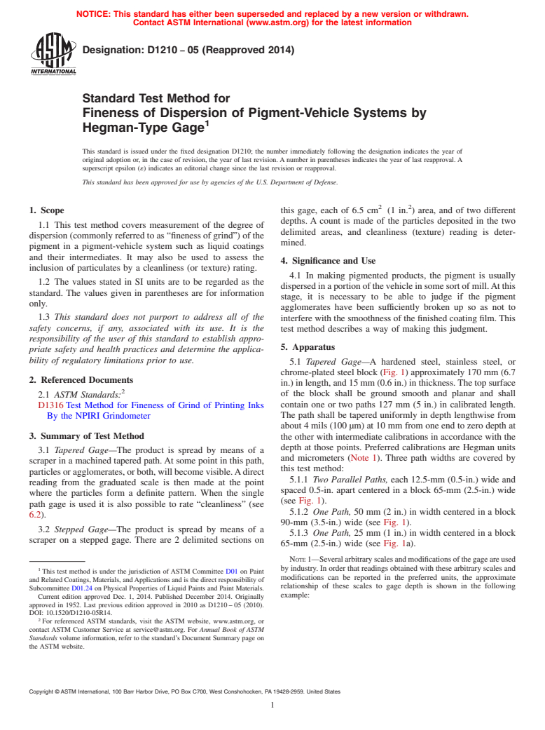
5.1 Tapered Gage—A hardened steel, stainless steel, or chrome-plated steel block (Fig. 1) approximately 170 mm (6.7 in.) in
length, and 15 mm (0.6 in.) in thickness. The top surface of the block shall be ground smooth and planar and shall contain one
or two paths 127 mm (5 in.) in calibrated length. The path shall be tapered uniformly in depth lengthwise from about 4 mils (100
μm) at 10 mm from one end to zero depth at the other with intermediate calibrations in accordance with the depth at those points.
Preferred calibrations are Hegman units and micrometers (Note 1). Three path widths are covered by this test method:
5.1.1 Two Parallel Paths, each 12.5-mm (0.5-in.) wide and spaced 0.5-in. apart centered in a block 65-mm (2.5-in.) wide (see
Fig. 1).
This test method is under the jurisdiction of ASTM Committee D01 on Paint and Related Coatings, Materials, and Applications and is the direct responsibility of
Subcommittee D01.24 on Physical Properties of Liquid Paints &and Paint Materials.
Current edition approved Feb. 1, 2010Dec. 1, 2014. Published February 2010December 2014. Originally approved in 1952. Last previous edition approved in 20052010
as D1210 – 05.D1210 – 05 (2010). DOI: 10.1520/D1210-05R10.10.1520/D1210-05R14.
For referenced ASTM standards, visit the ASTM website, www.astm.org, or contact ASTM Customer Service at service@astm.org. For Annual Book of ASTM Standards
volume information, refer to the standard’sstandard’s Document Summary page on the ASTM website.
Copyright © ASTM International, 100 Barr Harbor Drive, PO Box C700, West Conshohocken, PA 19428-2959. United States
D1210 − 05 (2014)
FIG. 1 Fineness Gages
5.1.2 One Path, 50 mm (2 in.) in width centered in a block 90-mm (3.5-in.) wide (see Fig. 1).
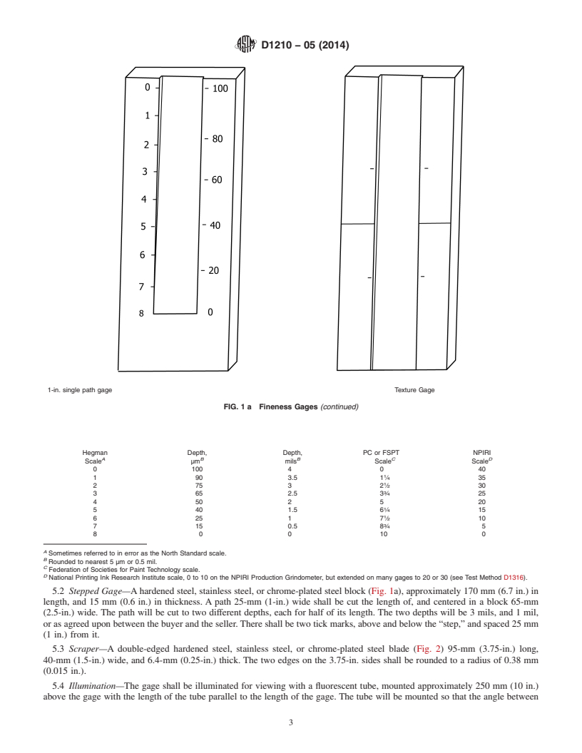
5.1.3 One Path, 25 mm (1 in.) in width centered in a block 65-mm (2.5-in.) wide (see Fig. 1a).
NOTE 1—Several arbitrary scales and modifications of the gage are used by industry. In order that readings obtained with these arbitrary scales and
modifications can be reported in the preferred units, the approximate relationship of these scales to gage depth is shown in the following example:
D1210 − 05 (2014)
1-in. single path gage Texture Gage
FIG. 1 a Fineness Gages (continued)
Hegman Depth, Depth, PC or FSPT NPIRI
A B B C D
Scale μm mils Scale Scale
0 100 4 0 40
1 90 3.5 1 ⁄4 35
2 75 3 2 ⁄2 30
3 65 2.5 3 ⁄4 25
4 50 2 5 20
5 40 1.5 6 ⁄4 15
6 25 1 7 ⁄2 10
7 15 0.5 8 ⁄4 5
8 0 0 10 0
A
Sometimes referred to in error as the North Standard scale.
B
Rounded to nearest 5 μm or 0.5 mil.
C
Federation of Societies for Paint Technology scale.
D
National Printing Ink Research Institute scale, 0 to 10 on the NPIRI Production Grindometer, but extended on many gages to 20 or 30 (see Test Method D1316).
5.2 Stepped Gage—A hardened steel, stainless steel, or chrome-plated steel block (Fig. 1a), approximately 170 mm (6.7 in.) in
length, and 15 mm (0.6 in.) in thickness. A path 25-mm (1-in.) wide shall be cut the length of, and centered in a block 65-mm
(2.5-in.) wide. The path will be cut to two different depths, each for half of its length. The two depths will be 3 mils, and 1 mil,
or as agreed upon between the buyer and the seller. There shall be two tick marks, above and below the “step,” and spaced 25 mm
(1 in.) from it.
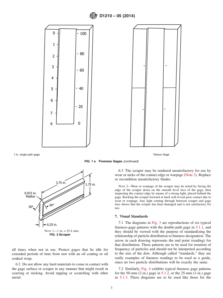
5.3 Scraper—A double-edged hardened steel, stainless steel, or chrome-plated steel blade (Fig. 2) 95-mm (3.75-in.) long,
40-mm (1.5-in.) wide, and 6.4-mm (0.25-in.) thick. The two edges on the 3.75-in. sides shall be rounded to a radius of 0.38 mm
(0.015 in.).
5.4 Illumination—The gage shall be illuminated for viewing with a fluorescent tube, mounted approximately 250 mm (10 in.)
above the gage with the length of the tube parallel to the length of the gage. The tube will be mounted so that the angle between
D1210 − 05 (2014)
NOTE 1—1 in. = 25.4 mm.
FIG. 2 Scraper
the plane of the gage, and the tube is 75 to 80°. A viewing box is not mandatory for illumination, but if one is desired, a proposed
design for a viewing box is contained in Appendix X1.
6. Care of Gage
6.1 Clean the gage immediately after each use. Use a solvent and a soft cloth. Keep the gage covered or encased at all times
when not in use. Protect gages that lie idle for extended periods of time from rust with an oil coating or oil soaked wrap.
6.2 Do not allow any hard materials to come in contact with the gage surface or scraper in any manner that might result in
scarring or nicking. Avoid tapping or scratching with other metal.
6.3 The scraper may be rendered unsatisfactory for use by wear or nicks of the contact edge or warpage (Note 2). Replace or
recondition unsatisfactory blades.
NOTE 2—Wear or warpage of the scraper may be noted by facing the edge of the scraper down on the smooth level face of the gage, then inspecting
the contact edge by means of a strong light, placed behind the gage. Rocking the scraper forward or back will reveal poor contact due to wear or warpage.
Any light coming through between scraper and gage face shows that the scraper has been damaged and is not satisfactory for use.
7. Visual Standards
7.1 The diagrams in Fig. 3 are reproductions of six typical fineness-gage patterns with the double-path gage in 5.1.1, and they
should be viewed with the purpose of standardizing the relationship of particle distribution to fineness designation. The arrow in
each drawing represents the end point (reading) for that distribution. These patterns are to be used for notation of frequency of
particles and should not be interpreted according to the size of the dots. Although called “standards,” they are really examples of
fineness readings to be used as a guide, since no two particle distributions will be exactly the same.
7.2 Similarly, Fig. 4 exhibits typical fineness gage patterns for the 50-mm (2-in.) gage in 5.1.2, or the 25-mm (1-in.) gage in
5.1.3. These diagrams are to be used like those for the double-path gage except that a “cleanliness” rating is also shown.
“Cleanliness” is descriptive of the number of particles that appear in the path above the fineness designation. Three ratings are
indicated: A (0 to 8 specks), B (9 to 15 specks), and C (16 or more specks).
8. Procedure—Tapered Gage
8.1 Place the gage on a horizontal flat, nonslippery surface and wipe clean immediately before the test. Be sure the gage surface
is free of lint.
8.2 Hand stir the specimen (Note 3) vigorously for 2 min, taking care that air bubbles are not whipped into the paint. To be sure
of an accurate grind reading, specimens must be free of air bubbles.
NOTE 3—For this test method to function properly, the pigment particles in the specimens to be tested should be free to settle to the bottom of the gage
channel after t
...
Questions, Comments and Discussion
Ask us and Technical Secretary will try to provide an answer. You can facilitate discussion about the standard in here.