


ASTM C201-93(2019)
(Test Method)Standard Test Method for Thermal Conductivity of Refractories
Standard Test Method for Thermal Conductivity of Refractories
SIGNIFICANCE AND USE
3.1 The thermal conductivity of refractories is a property required for selecting their thermal transmission characteristics. Users select refractories to provide specified conditions of heat loss and cold face temperature, without exceeding the temperature limitation of the refractory. This test method establishes the testing for thermal conductivity of refractories using the calorimeter.
3.2 This procedure requires a large thermal gradient and steady-state conditions. The results are based upon a mean temperature.
3.3 The data from this test method are suitable for specification acceptance and design of multi-layer refractory construction.
3.4 The use of these data requires consideration of the actual application environment and conditions.
SCOPE
1.1 This test method covers the determination of the comparative thermal conductivity of refractories under standardized conditions of testing. This test method is designed for refractories having a conductivity factor of not more than 200 Btu·in./h·ft2·°F (2818 W/m·K), for a thickness of 1 in. (25 mm).
1.2 Detailed ASTM test methods to be used in conjunction with this procedure in testing specific types of refractory materials are as follows: Test Method C182, Test Method C202, Test Method C417, and Test Method C767.
1.3 The values stated in inch-pound units are to be regarded as standard. The values given in parentheses are mathematical conversions to SI units that are provided for information only and are not considered standard.
1.4 This standard does not purport to address all of the safety concerns, if any, associated with its use. It is the responsibility of the user of this standard to establish appropriate safety, health, and environmental practices and determine the applicability of regulatory limitations prior to use.
1.5 This international standard was developed in accordance with internationally recognized principles on standardization established in the Decision on Principles for the Development of International Standards, Guides and Recommendations issued by the World Trade Organization Technical Barriers to Trade (TBT) Committee.
General Information
Buy Standard
Standards Content (Sample)
NOTICE: This standard has either been superseded and replaced by a new version or withdrawn.
Contact ASTM International (www.astm.org) for the latest information
Designation: C201 − 93 (Reapproved 2019)
Standard Test Method for
Thermal Conductivity of Refractories
This standard is issued under the fixed designation C201; the number immediately following the designation indicates the year of
original adoption or, in the case of revision, the year of last revision.Anumber in parentheses indicates the year of last reapproval.A
superscript epsilon (´) indicates an editorial change since the last revision or reapproval.
1. Scope C202Test Method for Thermal Conductivity of Refractory
Brick
1.1 This test method covers the determination of the com-
C417Test Method for Thermal Conductivity of Unfired
parative thermal conductivity of refractories under standard-
Monolithic Refractories
ized conditions of testing. This test method is designed for
C767Test Method for Thermal Conductivity of Carbon
refractories having a conductivity factor of not more than 200
2 Refractories
Btu·in./h·ft ·°F(2818W/m·K),forathicknessof1in.(25mm).
E220Test Method for Calibration of Thermocouples By
1.2 Detailed ASTM test methods to be used in conjunction
Comparison Techniques
with this procedure in testing specific types of refractory
materials are as follows: Test Method C182, Test Method
3. Significance and Use
C202, Test Method C417, and Test Method C767.
3.1 The thermal conductivity of refractories is a property
1.3 The values stated in inch-pound units are to be regarded
required for selecting their thermal transmission characteris-
as standard. The values given in parentheses are mathematical
tics.Usersselectrefractoriestoprovidespecifiedconditionsof
conversions to SI units that are provided for information only
heat loss and cold face temperature, without exceeding the
and are not considered standard.
temperature limitation of the refractory. This test method
establishes the testing for thermal conductivity of refractories
1.4 This standard does not purport to address all of the
using the calorimeter.
safety concerns, if any, associated with its use. It is the
responsibility of the user of this standard to establish appro-
3.2 This procedure requires a large thermal gradient and
priate safety, health, and environmental practices and deter-
steady-state conditions. The results are based upon a mean
mine the applicability of regulatory limitations prior to use.
temperature.
1.5 This international standard was developed in accor-
3.3 The data from this test method are suitable for specifi-
dance with internationally recognized principles on standard-
cation acceptance and design of multi-layer refractory con-
ization established in the Decision on Principles for the
struction.
Development of International Standards, Guides and Recom-
mendations issued by the World Trade Organization Technical 3.4 Theuseofthesedatarequiresconsiderationoftheactual
Barriers to Trade (TBT) Committee. application environment and conditions.
2. Referenced Documents
4. Apparatus
2.1 ASTM Standards:
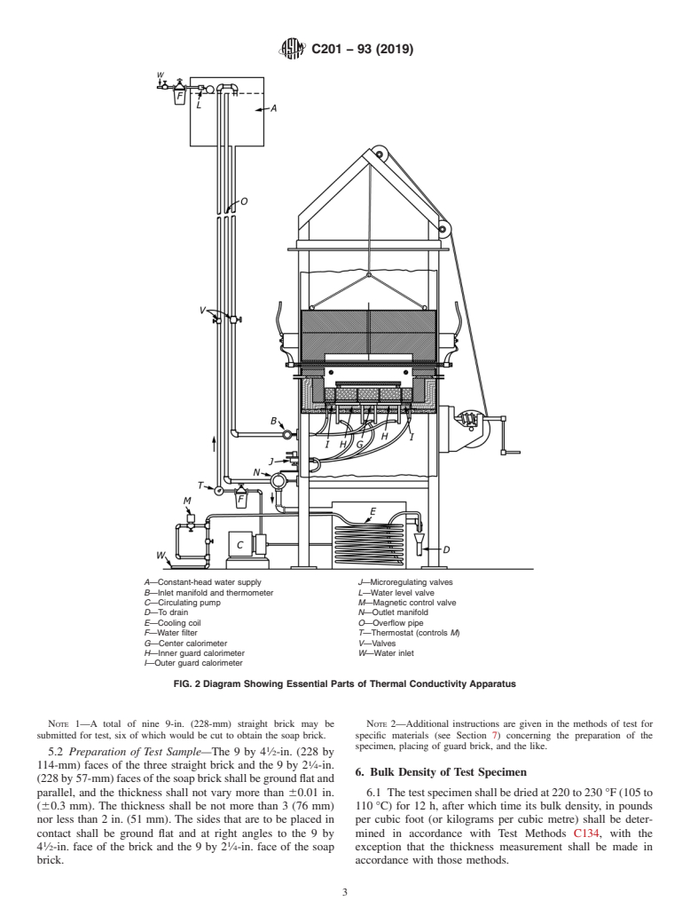
4.1 The apparatus shall conform in close detail with that
C134Test Methods for Size, Dimensional Measurements,
shown in the approved drawings. The equipment is shown in
and Bulk Density of Refractory Brick and Insulating
Figs. 1 and 2, and the essential parts are as follows:
Firebrick
4.1.1 Heating Chamber—Aheating chamber, shown in Fig.
C155Classification of Insulating Firebrick
3, shall be capable of being heated electrically over a tempera-
C182Test Method for Thermal Conductivity of Insulating
turerangefrom400to2800°F(205to1540°C)inaneutralor
Firebrick
oxidizingatmosphere.Thetemperatureoftheheatingunitshall
be controlled by a mechanism capable of maintaining the
This test method is under the jurisdiction of ASTM Committee C08 on
temperature in the chamber constant to within 65°F(63°C).
Refractories and is the direct responsibility of Subcommittee C08.02 on Thermal
Properties.
Current edition approved Jan. 1, 2019. Published January 2019. Originally
approved in 1945. Last previous edition approved in 2013 as C201–93 (2013). The complete set of approved drawings necessary for the construction of the
DOI: 10.1520/C0201-93R19. apparatus and suggested operating instructions, each of which requires too much
For referenced ASTM standards, visit the ASTM website, www.astm.org, or space to be included with this test method, was originally drafted by the Insulating
contact ASTM Customer Service at service@astm.org. For Annual Book of ASTM Products Division of Babcock and Wilcox Co. ASTM has been advised that these
Standards volume information, refer to the standard’s Document Summary page on drawings are no longer available. Subcommittee C08.02 is currently taking this
the ASTM website. issue under advisement.
Copyright © ASTM International, 100 Barr Harbor Drive, PO Box C700, West Conshohocken, PA 19428-2959. United States
C201 − 93 (2019)
pressure shall be at least the equivalent of 10 ft of hydrostatic
pressure (29.9 kPa). The inlet water temperature shall at all
times be within +5°F (+3°C) or −2°F (−1°C) of the room
temperature. Fig. 5 shows the arrangement that shall be used
for meeting these conditions. The regulating valves for con-
trollingtherateofwaterflowthroughthecalorimeterassembly
shall be capable of maintaining a constant rate of flow within
61% during the test period.
4.1.4 Instruments for Measuring Temperature of
Specimen—Calibrated thermocouples shall be embedded in
the test specimen for measuring the temperature. The electro-
motive force (emf) for the temperature readings shall be taken
with a potentiometer having an instrument error of not more
than 60.05 mV, and the cold junctions of the thermocouples
shall be immersed in a mixture of ice and water.
4.1.5 Instrument for Measuring Temperature Rise in Calo-
rimeter Water—A multiple differential thermocouple shall be
used for measuring within an accuracy of not less than 1% of
the temperature rise of the water flowing through the calorim-
eter. The thermocouple shall be immersed at least 3 ⁄2 in.
(89mm) in the inlet and outlet connections, and the junctions
shallbenotmorethan ⁄4in.(6mm)distantfromthebottomof
the calorimeter. A calibrated differential 10X copper-
constantan thermocouple shall be used, and the millivolt
readings shall be taken with a potentiometer having an instru-
ment error of not more than 60.01 mVin the range between 0
and2mV.
4.1.6 Instruments for Measuring Temperature Difference
BetweenCalorimeterandInnerGuard—Calibrateddifferential
NOTE 1—The upper half of the heating chamber has been raised to
10X copper-constantan thermocouples shall be located in the
permit introduction of the test samples.
calorimeter and inner guard for measuring the temperature
differences between the calorimeter and inner guard. The
FIG. 1 Photograph of Thermal Conductivity Apparatus
temperature difference during a test shall be maintained at a
value less than 60.05°F (60.03°C). The thermocouple junc-
A silicon carbide slab 13 ⁄2 by 9 by 1 in. (342 by 228 by
tions shall be placed in the four wells provided for that
25mm), with the 13 ⁄2 by 9-in. (342 by 228-mm) faces plane
purpose, and millivolt readings shall be taken with a potenti-
and parallel, shall be placed above the sample for the purpose
ometerhavinganinstrumenterrorofnotmorethan 60.01mV
of providing uniform heat distribution. A layer of insulation
in the range between 0 and 2 mV.
equivalent at least to 1 in. (25 mm) of Group 20 insulating
firebrick (see Classification C155) shall be placed below the 5. Test Sample and Its Preparation
calorimeter and guard plates.
5.1 TestSample—Thetestsampleshallconsistofthree9-in.
4.1.2 Calorimeter Assembly—A copper calorimeter
1 1
(228-mm)straightbrickandsix9by2 ⁄2by2 ⁄4-in.(228by64
assembly, of the design shown in Fig. 4, shall be used for
by 57-mm) soap brick (Note 2) that are representative of the
measuring the quantity of heat flowing through the test
material being tested. These brick shall be selected for unifor-
specimen. The water circulation is such that adjacent passages
mity of structure and bulk density, and they shall be free of
contain incoming and outgoing streams of water. The calorim-
broken corners or edges. One brick shall be used as the test
etershallbe3by3in.(76by76mm)squareandshallhaveone
specimen, and one each of the other two brick shall be used as
inlet and one outlet water connection. The inner guard sur-
guard brick on either side of the specimen. The six soap brick
rounding the calorimeter shall be 13 ⁄2 by 9 in. (342 by
shallbeplacedaroundtheedgesofthetestspecimenandguard
228mm) and shall have two inlet and two outlet water
b
...
This document is not an ASTM standard and is intended only to provide the user of an ASTM standard an indication of what changes have been made to the previous version. Because
it may not be technically possible to adequately depict all changes accurately, ASTM recommends that users consult prior editions as appropriate. In all cases only the current version
of the standard as published by ASTM is to be considered the official document.
Designation: C201 − 93 (Reapproved 2013) C201 − 93 (Reapproved 2019)
Standard Test Method for
Thermal Conductivity of Refractories
This standard is issued under the fixed designation C201; the number immediately following the designation indicates the year of
original adoption or, in the case of revision, the year of last revision. A number in parentheses indicates the year of last reapproval. A
superscript epsilon (´) indicates an editorial change since the last revision or reapproval.
1. Scope
1.1 This test method covers the determination of the comparative thermal conductivity of refractories under standardized
conditions of testing. This test method is designed for refractories having a conductivity factor of not more than 200 Btu·in./h·ft ·°F
(2818 W/m·K), for a thickness of 1 in. (25 mm).
1.2 Detailed ASTM test methods to be used in conjunction with this procedure in testing specific types of refractory materials
are as follows: Test Method C182, Test Method C202, Test Method C417, and Test Method C767.
1.3 The values stated in inch-pound units are to be regarded as standard. The values given in parentheses are mathematical
conversions to SI units that are provided for information only and are not considered standard.
1.4 This standard does not purport to address all of the safety concerns, if any, associated with its use. It is the responsibility
of the user of this standard to establish appropriate safety safety, health, and healthenvironmental practices and determine the
applicability of regulatory limitations prior to use.
1.5 This international standard was developed in accordance with internationally recognized principles on standardization
established in the Decision on Principles for the Development of International Standards, Guides and Recommendations issued
by the World Trade Organization Technical Barriers to Trade (TBT) Committee.
2. Referenced Documents
2.1 ASTM Standards:
C134 Test Methods for Size, Dimensional Measurements, and Bulk Density of Refractory Brick and Insulating Firebrick
C155 Classification of Insulating Firebrick
C182 Test Method for Thermal Conductivity of Insulating Firebrick
C202 Test Method for Thermal Conductivity of Refractory Brick
C417 Test Method for Thermal Conductivity of Unfired Monolithic Refractories
C767 Test Method for Thermal Conductivity of Carbon Refractories
E220 Test Method for Calibration of Thermocouples By Comparison Techniques
3. Significance and Use
3.1 The thermal conductivity of refractories is a property required for selecting their thermal transmission characteristics. Users
select refractories to provide specified conditions of heat loss and cold face temperature, without exceeding the temperature
limitation of the refractory. This test method establishes the testing for thermal conductivity of refractories using the calorimeter.
3.2 This procedure requires a large thermal gradient and steady state steady-state conditions. The results are based upon a mean
temperature.
3.3 The data from this test method are suitable for specification acceptance,acceptance and design of multi-layer refractory
construction.
3.4 The use of these data requires consideration of the actual application environment and conditions.
This test method is under the jurisdiction of ASTM Committee C08 on Refractories and is the direct responsibility of Subcommittee C08.02 on Thermal Properties.
Current edition approved Sept. 1, 2013Jan. 1, 2019. Published September 2013January 2019. Originally approved in 1945. Last previous edition approved in 20092013
as C201 – 93 (2009).(2013). DOI: 10.1520/C0201-93R13.10.1520/C0201-93R19.
For referenced ASTM standards, visit the ASTM website, www.astm.org, or contact ASTM Customer Service at service@astm.org. For Annual Book of ASTM Standards
volume information, refer to the standard’s Document Summary page on the ASTM website.
Copyright © ASTM International, 100 Barr Harbor Drive, PO Box C700, West Conshohocken, PA 19428-2959. United States
C201 − 93 (2019)
4. Apparatus
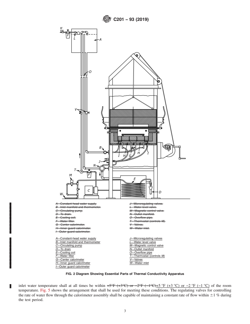
4.1 The apparatus shall conform in close detail with that shown in the approved drawings. The equipment is shown in Fig.
1Figs. 1 and 2 and Fig. 2, and the essential parts are as follows:
4.1.1 Heating Chamber—A heating chamber, shown in Fig. 3, shall be capable of being heated electrically over a temperature
range from 400 to 2800°F2800 °F (205 to 1540°C)1540 °C) in a neutral or oxidizing atmosphere. The temperature of the heating
unit shall be controlled by a mechanism capable of maintaining the temperature in the chamber constant to within 65°F
1 1
(63°C).65 °F (63 °C). A silicon carbide slab 13 ⁄2 by 9 by 1 in. (342 by 228 by 25 mm), 25 mm), with the 13 ⁄2 by 9-in. (342
by 228 mm) 228-mm) faces plane and parallel, shall be placed above the sample for the purpose of providing uniform heat
distribution. A layer of insulation equivalent at least to 1 in. (25 mm) of Group 20 insulating firebrick (see Classification C155)
shall be placed below the calorimeter and guard plates.
4.1.2 Calorimeter Assembly—A copper calorimeter assembly, of the design shown in Fig. 4, shall be used for measuring the
quantity of heat flowing through the test specimen. The water circulation is such that adjacent passages contain incoming and
outgoing streams of water. The calorimeter shall be 3 by 3 in. (76 by 76 mm) square and shall have one inlet and one outlet water
connection. The inner guard surrounding the calorimeter shall be 13 ⁄2 by 9 in. (342 by 228 mm) 228 mm) and shall have two inlet
and two outlet water connections. The outer guard shall extend 2 in. (51 mm) laterally from the inner guard and shall extend
vertically to the member comprising the bottom of the heating chamber (see Fig. 3). The separation between the calorimeter and
the inner guard shall be ⁄32 in. (0.8 mm).
4.1.3 Water-Circulating Water Circulating System—A water-circulating water circulating system shall be provided for supplying
the calorimeter assembly with water at constant pressure and at a temperature that is not changing at a rate greater than 1°F
(0.5°C)/h.1 °F (0.5 °C) ⁄h. The inlet water pressure shall be at least the equivalent of 10 ft of hydrostatic pressure (29.9 kPa). The
NOTE 1—The upper half of the heating chamber has been raised to permit introduction of the test samples.
FIG. 1 Photograph of Thermal Conductivity Apparatus
The complete set of approved drawings necessary for the construction of the apparatus and suggested operating instructions, each of which requires too much space to
be included with this test method, werewas originally drafted by the Insulating Products Division of Babcock and Wilcox Co. ASTM has been advised that these drawings
are no longer available. Subcommittee C08.05 currently C08.02 is currently taking this issue under advisement.
C201 − 93 (2019)
A—Constant-head water supply. J—Microregulating valves.
B—Inlet manifold and thermometer. L—Water-level valve.
C—Circulating pump. M—Magnetic control valve.
D—To drain. N—Outlet manifold.
E—Cooling coil. O—Overflow pipe.
F—Water filter. T—Thermostat (controls M).
G—Center calorimeter. V—Valves.
H—Inner guard calorimeter. W—Water inlet.
I—Outer guard calorimeter.
A—Constant-head water supply J—Microregulating valves
B—Inlet manifold and thermometer L—Water level valve
C—Circulating pump M—Magnetic control valve
D—To drain N—Outlet manifold
E—Cooling coil O—Overflow pipe
F—Water filter T—Thermostat (controls M)
G—Center calorimeter V—Valves
H—Inner guard calorimeter W—Water inlet
I—Outer guard calorimeter
FIG. 2 Diagram Showing Essential Parts of Thermal Conductivity Apparatus
inlet water temperature shall at all times be within +5°F (+3°C) or −2°F (−1°C)+5 °F (+3 °C) or −2 °F (−1 °C) of the room
temperature. Fig. 5 shows the arrangement that shall be used for meeting these conditions. The regulating valves for controlling
the rate of water flow through the calorimeter assembly shall be capable of maintaining a constant rate of flow within 61 % during
the test period.
C201 − 93 (2019)
NOTE 1—When testing insulating firebrick, the back-up insulation is removed.
FIG. 3 Diagrammatic Section Through Heating Chamber
FIG. 4 Design of Calorimeter and Guard Rings
4.1.4 Instruments for Measuring Temperature of Specimen—Calibrated thermocouples shall be embedded in the test specimen
for measuring the temperature. The electromotive force (emf) for the temperature readings shall be taken with a potentiometer
having an instrument error of not more than 60.05 mV, and the cold junctions of the thermocouples shall be immersed in a mixture
of ice and water.
Test Method E220 specifies calibration procedures for thermocouples.
C201 − 93 (2019)
C—Circulating pump. L—Water-level valve.
D—To drain. M—Magnetic control valve.
E—Cooling coil. O—Overflow pipe.
F—Water filter. T—Thermostat (controls M).
G—Center calorimeter. V—Valves.
H—Inner guard calorimeter. W—Water inlet.
I—Outer guard calorimeter.
...
Questions, Comments and Discussion
Ask us and Technical Secretary will try to provide an answer. You can facilitate discussion about the standard in here.