


ASTM D7616/D7616M-11(2017)
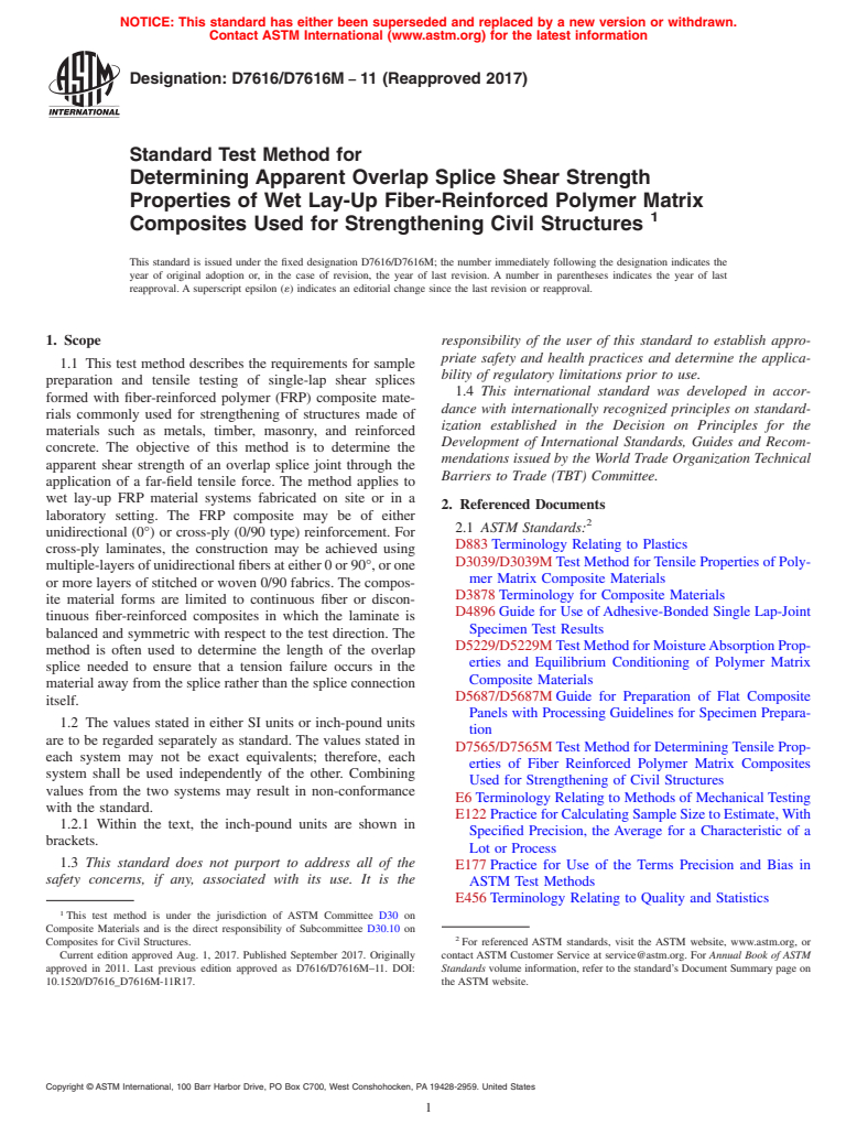
(Test Method)Standard Test Method for Determining Apparent Overlap Splice Shear Strength Properties of Wet Lay-Up Fiber-Reinforced Polymer Matrix Composites Used for Strengthening Civil Structures
Standard Test Method for Determining Apparent Overlap Splice Shear Strength Properties of Wet Lay-Up Fiber-Reinforced Polymer Matrix Composites Used for Strengthening Civil Structures
SIGNIFICANCE AND USE
5.1 Overlap splices are used in field applications of FRP composites when site conditions prohibit continuous access to a structural element or when the specified length of the FRP composite is such that saturation and placement of the entire length would be cumbersome. This method can be used as a quality control mechanism for ensuring that overlap splices constructed under field conditions meet or exceed the requirements established by the design engineer or FRP system manufacturer. Both the saturant mixing and fiber saturation method can be verified for wet-layup FRP systems.
5.2 Caution is recommended when interpreting apparent shear strength results obtained from this method. Single shear lap splices develop non-uniform shear stress distributions within the overlap splice region during testing. Additional guidance on the interpretation and use of results obtained from lap shear testing is found in D4896.
5.3 This test method focuses on the FRP material itself, irrespective of gripping method. Therefore, strengths resulting from failure or pullout at either grip are disregarded. The strength measurements are based solely on test specimens that fail in the gage section (away from the grips) or at the splice.
SCOPE
1.1 This test method describes the requirements for sample preparation and tensile testing of single-lap shear splices formed with fiber-reinforced polymer (FRP) composite materials commonly used for strengthening of structures made of materials such as metals, timber, masonry, and reinforced concrete. The objective of this method is to determine the apparent shear strength of an overlap splice joint through the application of a far-field tensile force. The method applies to wet lay-up FRP material systems fabricated on site or in a laboratory setting. The FRP composite may be of either unidirectional (0°) or cross-ply (0/90 type) reinforcement. For cross-ply laminates, the construction may be achieved using multiple-layers of unidirectional fibers at either 0 or 90°, or one or more layers of stitched or woven 0/90 fabrics. The composite material forms are limited to continuous fiber or discontinuous fiber-reinforced composites in which the laminate is balanced and symmetric with respect to the test direction. The method is often used to determine the length of the overlap splice needed to ensure that a tension failure occurs in the material away from the splice rather than the splice connection itself.
1.2 The values stated in either SI units or inch-pound units are to be regarded separately as standard. The values stated in each system may not be exact equivalents; therefore, each system shall be used independently of the other. Combining values from the two systems may result in non-conformance with the standard.
1.2.1 Within the text, the inch-pound units are shown in brackets.
1.3 This standard does not purport to address all of the safety concerns, if any, associated with its use. It is the responsibility of the user of this standard to establish appropriate safety and health practices and determine the applicability of regulatory limitations prior to use.
1.4 This international standard was developed in accordance with internationally recognized principles on standardization established in the Decision on Principles for the Development of International Standards, Guides and Recommendations issued by the World Trade Organization Technical Barriers to Trade (TBT) Committee.
General Information
Buy Standard
Standards Content (Sample)
NOTICE: This standard has either been superseded and replaced by a new version or withdrawn.
Contact ASTM International (www.astm.org) for the latest information
Designation: D7616/D7616M − 11 (Reapproved 2017)
Standard Test Method for
Determining Apparent Overlap Splice Shear Strength
Properties of Wet Lay-Up Fiber-Reinforced Polymer Matrix
Composites Used for Strengthening Civil Structures
This standard is issued under the fixed designation D7616/D7616M; the number immediately following the designation indicates the
year of original adoption or, in the case of revision, the year of last revision. A number in parentheses indicates the year of last
reapproval. A superscript epsilon (´) indicates an editorial change since the last revision or reapproval.
1. Scope responsibility of the user of this standard to establish appro-
priate safety and health practices and determine the applica-
1.1 This test method describes the requirements for sample
bility of regulatory limitations prior to use.
preparation and tensile testing of single-lap shear splices
1.4 This international standard was developed in accor-
formed with fiber-reinforced polymer (FRP) composite mate-
dance with internationally recognized principles on standard-
rials commonly used for strengthening of structures made of
ization established in the Decision on Principles for the
materials such as metals, timber, masonry, and reinforced
Development of International Standards, Guides and Recom-
concrete. The objective of this method is to determine the
mendations issued by the World Trade Organization Technical
apparent shear strength of an overlap splice joint through the
Barriers to Trade (TBT) Committee.
application of a far-field tensile force. The method applies to
wet lay-up FRP material systems fabricated on site or in a
2. Referenced Documents
laboratory setting. The FRP composite may be of either
2.1 ASTM Standards:
unidirectional (0°) or cross-ply (0/90 type) reinforcement. For
D883 Terminology Relating to Plastics
cross-ply laminates, the construction may be achieved using
D3039/D3039M Test Method for Tensile Properties of Poly-
multiple-layers of unidirectional fibers at either 0 or 90°, or one
mer Matrix Composite Materials
or more layers of stitched or woven 0/90 fabrics. The compos-
D3878 Terminology for Composite Materials
ite material forms are limited to continuous fiber or discon-
D4896 Guide for Use of Adhesive-Bonded Single Lap-Joint
tinuous fiber-reinforced composites in which the laminate is
Specimen Test Results
balanced and symmetric with respect to the test direction. The
D5229/D5229M Test Method for Moisture Absorption Prop-
method is often used to determine the length of the overlap
erties and Equilibrium Conditioning of Polymer Matrix
splice needed to ensure that a tension failure occurs in the
Composite Materials
material away from the splice rather than the splice connection
D5687/D5687M Guide for Preparation of Flat Composite
itself.
Panels with Processing Guidelines for Specimen Prepara-
1.2 The values stated in either SI units or inch-pound units
tion
are to be regarded separately as standard. The values stated in
D7565/D7565M Test Method for Determining Tensile Prop-
each system may not be exact equivalents; therefore, each
erties of Fiber Reinforced Polymer Matrix Composites
system shall be used independently of the other. Combining
Used for Strengthening of Civil Structures
values from the two systems may result in non-conformance
E6 Terminology Relating to Methods of Mechanical Testing
with the standard.
E122 Practice for Calculating Sample Size to Estimate, With
1.2.1 Within the text, the inch-pound units are shown in
Specified Precision, the Average for a Characteristic of a
brackets.
Lot or Process
1.3 This standard does not purport to address all of the
E177 Practice for Use of the Terms Precision and Bias in
safety concerns, if any, associated with its use. It is the
ASTM Test Methods
E456 Terminology Relating to Quality and Statistics
This test method is under the jurisdiction of ASTM Committee D30 on
Composite Materials and is the direct responsibility of Subcommittee D30.10 on
Composites for Civil Structures. For referenced ASTM standards, visit the ASTM website, www.astm.org, or
Current edition approved Aug. 1, 2017. Published September 2017. Originally contact ASTM Customer Service at service@astm.org. For Annual Book of ASTM
approved in 2011. Last previous edition approved as D7616/D7616M–11. DOI: Standards volume information, refer to the standard’s Document Summary page on
10.1520/D7616_D7616M-11R17. the ASTM website.
Copyright © ASTM International, 100 Barr Harbor Drive, PO Box C700, West Conshohocken, PA 19428-2959. United States
D7616/D7616M − 11 (2017)
2.2 Other Standards: 3.3.7 L'—length of the overlap splice region
DOT/FAA/AR-01/33 Investigation of Thick Bondline Adhe-
3.3.8 n—number of specimens.
sive Joints, June 2001
3.3.9 P—force carried by test specimen.
DOT/FAA/AR-02/97 Shear Stress-Strain Data for Structural
max
3.3.10 P —maximum tensile force.
Adhesives, November 2002
3.3.11 w—coupon width.
3. Terminology
3.3.12 V*—apparent shear strength of the overlap splice per
3.1 Definitions—Terminology D3878 defines terms relating unit width for the L' under consideration.
to high-modulus fibers and their composites. Terminology
4. Summary of Test Method
D883 defines terms relating to plastics. Terminology E6 defines
terms relating to mechanical testing. Terminology E456 and
4.1 Overlap splice specimens are prepared using a wet
Practice E177 define terms relating to statistics. In the event of lay-up procedure. Wet lay-up material may be prepared in a
a conflict between terms, Terminology D3878 shall have
laboratory or field setting, as the testing objectives dictate. For
precedence over the other standards. testing in single shear, two thin, flat strips of material having a
nominally constant cross section are joined together with a
3.2 Definitions of Terms Specific to This Standard:
specified overlap and allowed to cure. The cured specimen is
3.2.1 nominal value, n—a value, existing in name only,
mounted in the grips of a mechanical testing machine and
assigned to a measurable property for the purpose of conve-
monotonically loaded in tension while force is recorded. The
nient designation. Tolerances may be applied to a nominal
following items are reported for each specimen: ultimate force
value to define an acceptable range for the property.
at failure, failure mode, and the apparent shear strength per unit
3.2.2 screed, v—to move a flat rule along the top of a
width at failure.
saturated laminate to level the top of the laminate and
simultaneously remove excess resin.
5. Significance and Use
3.2.3 wet lay-up FRP composite, n—an FRP composite
5.1 Overlap splices are used in field applications of FRP
material fabricated by manually impregnating dry fibers with a
composites when site conditions prohibit continuous access to
matrix of polymeric resin. Semi-automated processes such as
a structural element or when the specified length of the FRP
machine-aided wetting of fabrics before placement or vacuum
composite is such that saturation and placement of the entire
aided impregnation of laminates after placement are considered
length would be cumbersome. This method can be used as a
part of wet lay-up FRP. For civil infrastructure strengthening
quality control mechanism for ensuring that overlap splices
applications, the degree of control over the volume fractions of
constructed under field conditions meet or exceed the require-
fibers, matrix, and voids as well as the overall cross-sectional
ments established by the design engineer or FRP system
geometry in wet lay-up FRP composites may be less than that
manufacturer. Both the saturant mixing and fiber saturation
for shop manufactured FRP composites on account of the
method can be verified for wet-layup FRP systems.
manual process. For strengthening applications, wet lay-up
5.2 Caution is recommended when interpreting apparent
FRP composites are typically applied to the substrate at the
shear strength results obtained from this method. Single shear
same time the dry fiber is impregnated. The impregnating resin
lap splices develop non-uniform shear stress distributions
may act as the saturant for the FRP composite as well as the
within the overlap splice region during testing. Additional
bonding agent between the composite reinforcement and the
guidance on the interpretation and use of results obtained from
substrate. Wet lay-up specimens may be fabricated in either a
lap shear testing is found in D4896.
field or a laboratory setting.
5.3 This test method focuses on the FRP material itself,
3.3 Symbols:
irrespective of gripping method. Therefore, strengths resulting
3.3.1 F*—strength of FRP laminate per unit width.
from failure or pullout at either grip are disregarded. The
3.3.2 h —laminate thickness measured outside of the over-
strength measurements are based solely on test specimens that
lap splice on the bottom (flat) laminate.
fail in the gage section (away from the grips) or at the splice.
3.3.3 h —laminate thickness measured outside of the over-
6. Interferences
lap splice on the top (kinked) laminate.
6.1 A summary of the interferences, specifically material
3.3.4 h —laminate thickness measured within the overlap
and specimen preparation, gripping, system alignment, and
splice region.
edge effects in cross-ply laminates, are presented in D3039/
3.3.5 h' —the reference thickness of a fiber, fabric or
D3039M.
preform layer without resin, measured outside of the overlap
6.2 Additional interferences may arise from lack of control
splice.
in wet lay-up specimen preparation procedures outlined in
3.3.6 L—entire length of the overlap splice specimen in-
8.3.1. Specimen variations in resin content, ply thickness, void
cluding the portion dedicated to gripping.
content and degree of cure may contribute to variability in test
results.
3 6.3 Construction of single lap-splice samples using wet-lay
Available at the Federal Aviation Administration William J. Hughes Technical
Center Full-Text Technical Reports page: http://207.67.203.68/F10011. FRP will result in kinked fibers for the top laminate (see Fig.
D7616/D7616M − 11 (2017)
1). The effects of this kink on lap shear results will be overlap splice lengths. Variation in the overlap splice length as
magnified as the thickness, h and h , of the FRP increases. measured along both edges of the specimen shall be no greater
1 2
This kink may also result in laminate failure outside the region than 6 5 %.
of the bondline and the severity of the kink can impart moment
8.2.2 Specimen Width—Minimum specimen width for uni-
loading to the bonded joint.
directional wet lay-up FRP specimens shall be 25 mm [1.0 in.].
Minimum width for cross-ply specimens shall be 38 mm [1.5
6.4 Overlap splice length, L’, is identified in D4896, section
in.] for wet lay-up composites. Variation in specimen width
5.3.2 as a geometric parameter which affects apparent shear
shall be no greater than 6 1 %.
strength properties obtained from overlap splice tests. The
results obtained using this test method are valid exclusively for
8.3 Specimen Preparation:
the overlap splice length under consideration.
8.3.1 Wet Lay-up FRP—Make field-prepared specimens in a
6.5 If a supplementary adhesive material (e.g., thickened
manner similar to the actual field installation of the material. A
epoxy tack coat) is used to promote bond between composite
polymer release film, typically 600 × 600 mm [24 × 24 in.] is
layers within the overlap splice region, it should be noted that
placed on a smooth, flat horizontal surface. The release film
variations in the bond-line thickness may result in different
shall be at least 0.076 mm [0.003 in.] thick and made of a
apparent shear strength values or different failure modes. The
polymer that will not adhere to the resin used to impregnate the
typically observed trend is that increasing bondline thickness
fibers. Usually, acetate and nylon are acceptable. Resin is first
results in decreased apparent shear strength (DOT/FAA/AR-
applied to the release film. The dimensions of each ply should
01/33 and DOT/FAA/AR-02/97).
be no less than 150 × 300 mm [6 × 12 in.] (or longer as
6.6 The fiber/ply orientation within the overlap splice region required by the specimen size, see Fig. 2). In order to facilitate
has also been shown to influence the apparent shear strength or the construction of the overlap splice joint and to ensure the
failure mode, or both, in lap shear specimens (DOT/FAA/AR- desired overlap splice length, L', is obtained, the width of the
02/97). bottom laminate may be slightly larger (5 – 10 mm) than the
width of the top laminate. Any excess material present in the
6.7 The temperature and moisture conditions experienced
bottom laminate shall be removed and discarded during the
by a specimen during curing and load testing can affect the
specimen machining process described in 8.3.4. The dry fibers
apparent shear strength of an overlap splice joint. Additional
are saturated or coated with the specified amount of resin and
guidance is provided in D3039/D3039M, section 11.4.
placed on the release film. This can be done using a properly
calibrated saturator machine or using a manufacturer-specified
7. Apparatus
fiber to resin weight ratio. The specified number of plies at the
7.1 Requirements for testing machines and instrumentation
specified angles (0 or 90°) for the bottom laminate of the single
are the same as those given in D3039/D3039M, Section 7.
lap splice are sequentially impregnated with resin and stacked
8. Sampling and Test Specimens onto the release film using the specified amount of resin per ply
per unit area as in the actual installation. Using the flat edge of
8.1 Sampling—Test at least five specimens per test condi-
a small hand tool or a grooved roller, air bubbles are worked
tion unless valid results can be gained through the use of fewer
out of the material. The bubbles shall be worked out in the
specimens, such as in the case of a designed experiment. For
direction of the primary fibers to ensure that no damage is
statistically significant data, the procedures outlined in Practice
caused to the fibers. At this point the specified number of plies
E122 shall be consulted. Report the method of sampling.
for the top laminate of the lap splice are sequentially impreg-
NOTE 1—If specimens are to undergo environmental conditioning to
nated with resin and stacked onto a second piece of release
equilibrium, and are of such type or geometry that the weight change of
film. If a supplementary adhesive material is specified, it shall
the material cannot be properly measured by weighing the specimen itself
be applied uniformly to both saturated laminates in the region
(such
...
This document is not an ASTM standard and is intended only to provide the user of an ASTM standard an indication of what changes have been made to the previous version. Because
it may not be technically possible to adequately depict all changes accurately, ASTM recommends that users consult prior editions as appropriate. In all cases only the current version
of the standard as published by ASTM is to be considered the official document.
Designation: D7616/D7616M − 11 D7616/D7616M − 11 (Reapproved 2017)
Standard Test Method for
Determining Apparent Overlap Splice Shear Strength
Properties of Wet Lay-Up Fiber-Reinforced Polymer Matrix
Composites Used for Strengthening Civil Structures
This standard is issued under the fixed designation D7616/D7616M; the number immediately following the designation indicates the
year of original adoption or, in the case of revision, the year of last revision. A number in parentheses indicates the year of last
reapproval. A superscript epsilon (´) indicates an editorial change since the last revision or reapproval.
1. Scope
1.1 This test method describes the requirements for sample preparation and tensile testing of single-lap shear splices formed
with fiber-reinforced polymer (FRP) composite materials commonly used for strengthening of structures made of materials such
as metals, timber, masonry, and reinforced concrete. The objective of this method is to determine the apparent shear strength of
an overlap splice joint through the application of a far-field tensile force. The method applies to wet lay-up FRP material systems
fabricated on site or in a laboratory setting. The FRP composite may be of either unidirectional (0°) or cross-ply (0/90 type)
reinforcement. For cross-ply laminates, the construction may be achieved using multiple-layers of unidirectional fibers at either
0 or 90°, or one or more layers of stitched or woven 0/90 fabrics. The composite material forms are limited to continuous fiber
or discontinuous fiber-reinforced composites in which the laminate is balanced and symmetric with respect to the test direction.
The method is often used to determine the length of the overlap splice needed to ensure that a tension failure occurs in the material
away from the splice rather than the splice connection itself.
1.2 The values stated in either SI units or inch-pound units are to be regarded separately as standard. The values stated in each
system may not be exact equivalents; therefore, each system shall be used independently of the other. Combining values from the
two systems may result in non-conformance with the standard.
1.2.1 Within the text, the inch-pound units are shown in brackets.
1.3 This standard does not purport to address all of the safety concerns, if any, associated with its use. It is the responsibility
of the user of this standard to establish appropriate safety and health practices and determine the applicability of regulatory
limitations prior to use.
1.4 This international standard was developed in accordance with internationally recognized principles on standardization
established in the Decision on Principles for the Development of International Standards, Guides and Recommendations issued
by the World Trade Organization Technical Barriers to Trade (TBT) Committee.
2. Referenced Documents
2.1 ASTM Standards:
D883 Terminology Relating to Plastics
D3039/D3039M Test Method for Tensile Properties of Polymer Matrix Composite Materials
D3878 Terminology for Composite Materials
D4896 Guide for Use of Adhesive-Bonded Single Lap-Joint Specimen Test Results
D5229/D5229M Test Method for Moisture Absorption Properties and Equilibrium Conditioning of Polymer Matrix Composite
Materials
D5687/D5687M Guide for Preparation of Flat Composite Panels with Processing Guidelines for Specimen Preparation
D7565/D7565M Test Method for Determining Tensile Properties of Fiber Reinforced Polymer Matrix Composites Used for
Strengthening of Civil Structures
E6 Terminology Relating to Methods of Mechanical Testing
This test method is under the jurisdiction of ASTM Committee D30 on Composite Materials and is the direct responsibility of Subcommittee D30.10 on Composites
for Civil Structures.
Current edition approved March 1, 2011Aug. 1, 2017. Published May 2011September 2017. Originally approved in 2011. Last previous edition approved as
D7616/D7616M–11. DOI: 10.1520/D7616_D7616M-11.10.1520/D7616_D7616M-11R17.
For referenced ASTM standards, visit the ASTM website, www.astm.org, or contact ASTM Customer Service at service@astm.org. For Annual Book of ASTM Standards
volume information, refer to the standard’s Document Summary page on the ASTM website.
Copyright © ASTM International, 100 Barr Harbor Drive, PO Box C700, West Conshohocken, PA 19428-2959. United States
D7616/D7616M − 11 (2017)
E122 Practice for Calculating Sample Size to Estimate, With Specified Precision, the Average for a Characteristic of a Lot or
Process
E177 Practice for Use of the Terms Precision and Bias in ASTM Test Methods
E456 Terminology Relating to Quality and Statistics
2.2 Other Standards:
DOT/FAA/AR-01/33 Investigation of Thick Bondline Adhesive Joints, June 2001
DOT/FAA/AR-02/97 Shear Stress-Strain Data for Structural Adhesives, November 2002
3. Terminology
3.1 Definitions—Terminology D3878 defines terms relating to high-modulus fibers and their composites. Terminology D883
defines terms relating to plastics. Terminology E6 defines terms relating to mechanical testing. Terminology E456 and Practice
E177 define terms relating to statistics. In the event of a conflict between terms, Terminology D3878 shall have precedence over
the other standards.
3.2 Definitions of Terms Specific to This Standard:
3.2.1 nominal value, n—a value, existing in name only, assigned to a measurable property for the purpose of convenient
designation. Tolerances may be applied to a nominal value to define an acceptable range for the property.
3.2.2 screed, v—to move a flat rule along the top of a saturated laminate to level the top of the laminate and simultaneously
remove excess resin.
3.2.3 wet lay-up FRP composite, n—an FRP composite material fabricated by manually impregnating dry fibers with a matrix
of polymeric resin. Semi-automated processes such as machine-aided wetting of fabrics before placement or vacuum aided
impregnation of laminates after placement are considered part of wet lay-up FRP. For civil infrastructure strengthening
applications, the degree of control over the volume fractions of fibers, matrix, and voids as well as the overall cross-sectional
geometry in wet lay-up FRP composites may be less than that for shop manufactured FRP composites on account of the manual
process. For strengthening applications, wet lay-up FRP composites are typically applied to the substrate at the same time the dry
fiber is impregnated. The impregnating resin may act as the saturant for the FRP composite as well as the bonding agent between
the composite reinforcement and the substrate. Wet lay-up specimens may be fabricated in either a field or a laboratory setting.
3.3 Symbols:
3.3.1 F*—strength of FRP laminate per unit width.
3.3.2 h —laminate thickness measured outside of the overlap splice on the bottom (flat) laminate.
3.3.3 h —laminate thickness measured outside of the overlap splice on the top (kinked) laminate.
3.3.4 h —laminate thickness measured within the overlap splice region.
3.3.5 h' —the reference thickness of a fiber, fabric or preform layer without resin, measured outside of the overlap splice.
3.3.6 L—entire length of the overlap splice specimen including the portion dedicated to gripping.
3.3.7 L'—length of the overlap splice region
3.3.8 n—number of specimens.
3.3.9 P—force carried by test specimen.
max
3.3.10 P —maximum tensile force.
3.3.11 w—coupon width.
3.3.12 V*—apparent shear strength of the overlap splice per unit width for the L' under consideration.
4. Summary of Test Method
4.1 Overlap splice specimens are prepared using a wet lay-up procedure. Wet lay-up material may be prepared in a laboratory
or field setting, as the testing objectives dictate. For testing in single shear, two thin, flat strips of material having a nominally
constant cross section are joined together with a specified overlap and allowed to cure. The cured specimen is mounted in the grips
of a mechanical testing machine and monotonically loaded in tension while force is recorded. The following items are reported
for each specimen: ultimate force at failure, failure mode, and the apparent shear strength per unit width at failure.
5. Significance and Use
5.1 Overlap splices are used in field applications of FRP composites when site conditions prohibit continuous access to a
structural element or when the specified length of the FRP composite is such that saturation and placement of the entire length
would be cumbersome. This method can be used as a quality control mechanism for ensuring that overlap splices constructed under
Available at the Federal Aviation Administration William J. Hughes Technical Center Full-Text Technical Reports page: http://207.67.203.68/F10011.
D7616/D7616M − 11 (2017)
field conditions meet or exceed the requirements established by the design engineer or FRP system manufacturer. Both the saturant
mixing and fiber saturation method can be verified for wet-layup FRP systems.
5.2 Caution is recommended when interpreting apparent shear strength results obtained from this method. Single shear lap
splices develop non-uniform shear stress distributions within the overlap splice region during testing. Additional guidance on the
interpretation and use of results obtained from lap shear testing is found in D4896.
5.3 This test method focuses on the FRP material itself, irrespective of gripping method. Therefore, strengths resulting from
failure or pullout at either grip are disregarded. The strength measurements are based solely on test specimens that fail in the gage
section (away from the grips) or at the splice.
6. Interferences
6.1 A summary of the interferences, specifically material and specimen preparation, gripping, system alignment, and edge
effects in cross-ply laminates, are presented in D3039/D3039M.
6.2 Additional interferences may arise from lack of control in wet lay-up specimen preparation procedures outlined in 8.3.1.
Specimen variations in resin content, ply thickness, void content and degree of cure may contribute to variability in test results.
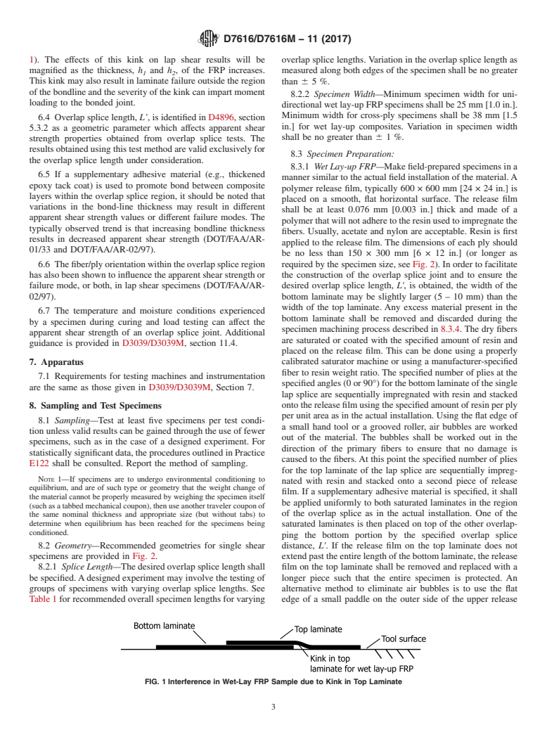
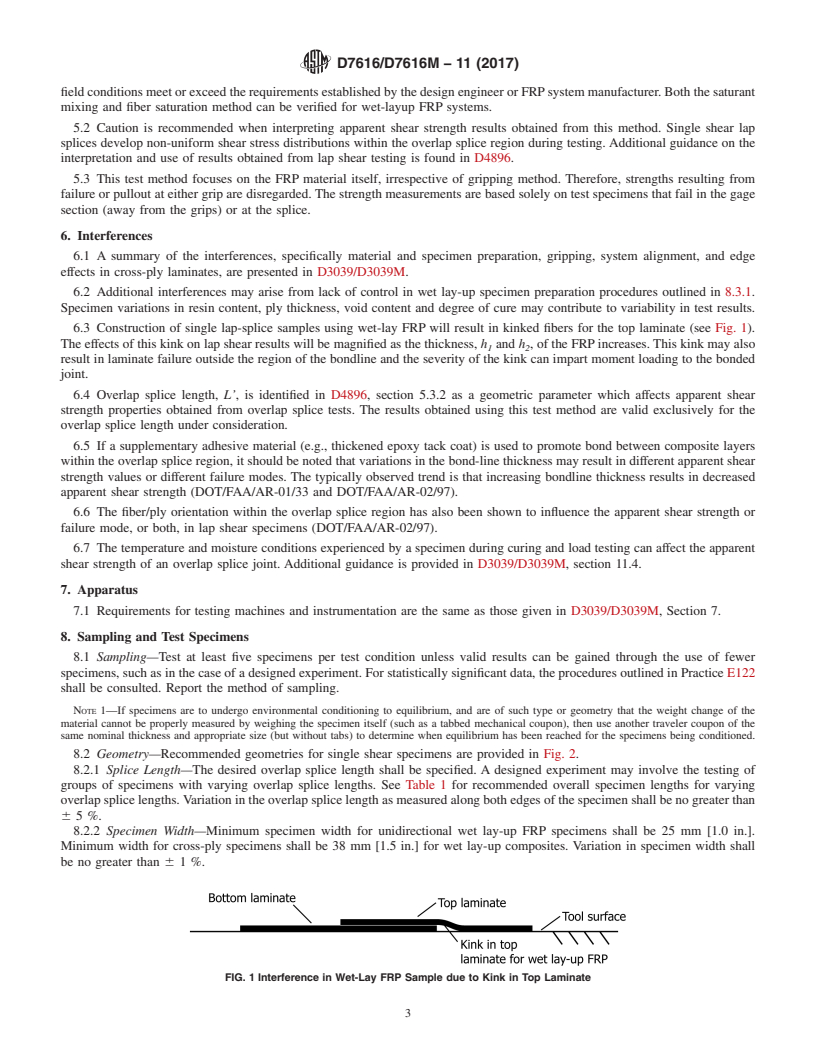
6.3 Construction of single lap-splice samples using wet-lay FRP will result in kinked fibers for the top laminate (see Fig. 1).
The effects of this kink on lap shear results will be magnified as the thickness, h and h , of the FRP increases. This kink may also
1 2
result in laminate failure outside the region of the bondline and the severity of the kink can impart moment loading to the bonded
joint.
6.4 Overlap splice length, L’, is identified in D4896, section 5.3.2 as a geometric parameter which affects apparent shear
strength properties obtained from overlap splice tests. The results obtained using this test method are valid exclusively for the
overlap splice length under consideration.
6.5 If a supplementary adhesive material (e.g., thickened epoxy tack coat) is used to promote bond between composite layers
within the overlap splice region, it should be noted that variations in the bond-line thickness may result in different apparent shear
strength values or different failure modes. The typically observed trend is that increasing bondline thickness results in decreased
apparent shear strength (DOT/FAA/AR-01/33 and DOT/FAA/AR-02/97).
6.6 The fiber/ply orientation within the overlap splice region has also been shown to influence the apparent shear strength or
failure mode, or both, in lap shear specimens (DOT/FAA/AR-02/97).
6.7 The temperature and moisture conditions experienced by a specimen during curing and load testing can affect the apparent
shear strength of an overlap splice joint. Additional guidance is provided in D3039/D3039M, section 11.4.
7. Apparatus
7.1 Requirements for testing machines and instrumentation are the same as those given in D3039/D3039M, Section 7.
8. Sampling and Test Specimens
8.1 Sampling—Test at least five specimens per test condition unless valid results can be gained through the use of fewer
specimens, such as in the case of a designed experiment. For statistically significant data, the procedures outlined in Practice E122
shall be consulted. Report the method of sampling.
NOTE 1—If specimens are to undergo environmental conditioning to equilibrium, and are of such type or geometry that the weight change of the
material cannot be properly measured by weighing the specimen itself (such as a tabbed mechanical coupon), then use another traveler coupon of the
same nominal thickness and appropriate size (but without tabs) to determine when equilibrium has been reached for the specimens being conditioned.
8.2 Geometry—Recommended geometries for single shear specimens are provided in Fig. 2.
8.2.1 Splice Length—The desired overlap splice length shall be specified. A designed experiment may involve the testing of
groups of specimens with varying overlap splice lengths. See Table 1 for recommended overall specimen lengths for varying
overlap splice lengths. Variation in the overlap splice length as measured along both edges of the specimen shall be no greater than
6 5 %.
8.2.2 Specimen Width—Minimum specimen width for unidirectional wet lay-up FRP specimens shall be 25 mm [1.0 in.].
Minimum width for cross-ply specimens shall be 38 mm [1.5 in.] for wet lay-up composites. Variation in specimen width shall
be no greater than 6 1 %.
FIG. 1 Interference in Wet-Lay FRP Sample due to Kink in Top Laminate
D7616/D7616M − 11 (2017)
FIG. 2 Dimensions for Single-Shear Wet Lay-Up FRP Specimens
TABLE 1 Overall Specimen Length, L, as a Function of Overlap
Splice Length, L'
Overlap length (L') Minimum
A
mm Specimen length (L)
B
A
(in)
mm
B
(in)
25.0 (1.00) 230.0 (9.00)
50.0 (2.00) 260.0 (10.00)
76.0 (3.00) 280.0 (11.00)
100.0 (4.00) 305.0 (12.00)
150.0 (6.00) 360.0 (14.00)
200.0 (8.00) 410.0 (16.00)
A
Tolerances for millimeter dimensions are +/- 1.0 mm.
B
Tolerances for inch dimensions are +/- 0.04 in.
8.3 Specimen Preparation:
8.3.1 Wet Lay-up FRP—Make field-prepared specimens in a manner similar to the actual field installation of the material. A
polymer release film, typically 600 × 600 mm [24 × 24 in.] is placed on a smooth, flat horizontal surface. The release film shall
be at least 0.076 mm [0.003 in.] thick and made of a polymer that will not adhere to the resin used to impregnate the fibers. Usually,
acetate and nylon are acceptable. Resin is first applied to the release film. The dimensions of each ply should be no less than 150
× 300 mm [6 × 12 in.] (or longer as required by the specimen s
...
Questions, Comments and Discussion
Ask us and Technical Secretary will try to provide an answer. You can facilitate discussion about the standard in here.