


ASTM D955-08(2014)
(Test Method)Standard Test Method of Measuring Shrinkage from Mold Dimensions of Thermoplastics
Standard Test Method of Measuring Shrinkage from Mold Dimensions of Thermoplastics
SIGNIFICANCE AND USE
5.1 Injection Molding—In injection molding, the difference between the dimensions of a mold cavity and of the molded specimen may vary according to the design of the mold and operation of the molding process. Factors such as mold and melt temperature, fill times, and packing conditions are known to affect shrinkage significantly. Adherence to the specified mold design (see 7.1) and specifications outlined in Practice D3641 or ISO 294-4 or the appropriate material specification will improve the reproducibility of the test.
5.2 Compression Molding—In compression molding, the difference between the dimensions of a mold cavity and of the molded specimen may vary according to the design of the mold and operation of the molding process. Factors, such as the amount of material in charge, cooling time, and pressure application are known to affect shrinkage significantly. Adherence to the specified mold design (see 7.2) and specifications outlined in Practice D4703 or ISO 293 or the appropriate material specifications will improve the reproducibility of the test.
SCOPE
1.1 This test method is intended to measure shrinkage from mold cavity to molded dimensions of thermoplastics when molded by compression or injection processes with specified process conditions.
1.2 This test method covers shrinkage measurements at 24 and 48 hours.
1.3 This method will give comparable data based on standard specimens and can not predict absolute values in actual molded parts with varying flow paths, wall thicknesses, pressure and temperature gradients and process conditions. Differences in mold shrinkage may also be observed among the three specimen geometries described in this test method.
1.4 The values stated in SI units are to be regarded as the standard. The values given in parentheses are given for information only.
1.5 This standard does not purport to address all of the safety concerns, if any, associated with its use. It is the responsibility of the user of this standard to establish appropriate safety and health practices and determine the applicability of regulatory limitations prior to use.
Note 1: This standard and ISO 294-3 are equivalent in the design of specimen D2. This test method is equivalent to ISO 294-4 where Type D2 specimens and the procedure in Appendix X2 are used.
General Information
Buy Standard
Standards Content (Sample)
NOTICE: This standard has either been superseded and replaced by a new version or withdrawn.
Contact ASTM International (www.astm.org) for the latest information
Designation: D955 − 08 (Reapproved 2014)
Standard Test Method of
Measuring Shrinkage from Mold Dimensions of
Thermoplastics
This standard is issued under the fixed designation D955; the number immediately following the designation indicates the year of
original adoption or, in the case of revision, the year of last revision.Anumber in parentheses indicates the year of last reapproval.A
superscript epsilon (´) indicates an editorial change since the last revision or reapproval.
This standard has been approved for use by agencies of the U.S. Department of Defense.
1. Scope D3641Practice for Injection Molding Test Specimens of
Thermoplastic Molding and Extrusion Materials
1.1 This test method is intended to measure shrinkage from
D4066Classification System for Nylon Injection and Extru-
mold cavity to molded dimensions of thermoplastics when
sion Materials (PA)
molded by compression or injection processes with specified
D4549Classification System and Basis for Specification for
process conditions.
Polystyrene and Rubber-Modified Polystyrene Molding
1.2 This test method covers shrinkage measurements at 24
and Extrusion Materials (PS)
and 48 hours.
D4703Practice for Compression Molding Thermoplastic
1.3 This method will give comparable data based on stan-
Materials into Test Specimens, Plaques, or Sheets
dard specimens and can not predict absolute values in actual D4976Specification for Polyethylene Plastics Molding and
molded parts with varying flow paths, wall thicknesses, pres-
Extrusion Materials
sure and temperature gradients and process conditions. Differ- D5947Test Methods for Physical Dimensions of Solid
encesinmoldshrinkagemayalsobeobservedamongthethree
Plastics Specimens
specimen geometries described in this test method. D6778Classification System and Basis for Specification for
Polyoxymethylene Molding and Extrusion Materials
1.4 The values stated in SI units are to be regarded as the
(POM)
standard. The values given in parentheses are given for
D6779Classification System for and Basis of Specification
information only.
for Polyamide Molding and Extrusion Materials (PA)
1.5 This standard does not purport to address all of the
E691Practice for Conducting an Interlaboratory Study to
safety concerns, if any, associated with its use. It is the
Determine the Precision of a Test Method
responsibility of the user of this standard to establish appro-
2.2 ISO Standards:
priate safety and health practices and determine the applica-
ISO 293Plastics—Compression Moulding Test Specimens
bility of regulatory limitations prior to use.
of Thermoplastic Materials
NOTE 1—This standard and ISO 294-3 are equivalent in the design of
ISO 294-1Plastics—Injection Moulding of Test Specimens
specimenD2.ThistestmethodisequivalenttoISO294-4whereTypeD2
of Thermoplastic Materials—Part 1: General Principles,
specimens and the procedure in Appendix X2 are used.
and Moulding of Multipurpose and Bar Test specimens
2. Referenced Documents
ISO 294-3Plastics—Injection Moulding of Test Specimens
of Thermoplastic Materials—Part 3: Small Plates
2.1 ASTM Standards:
ISO 294-4 Plastics—Injection Moulding of Test
D618Practice for Conditioning Plastics for Testing
Specimens—Part 4: Determination of Moulding Shrink-
D788Classification System for Poly(Methyl Methacrylate)
age
(PMMA) Molding and Extrusion Compounds
D883Terminology Relating to Plastics
3. Terminology
3.1 Definitions—General definitions of terms applying to
ThistestmethodisunderthejurisdictionofASTMCommitteeD20onPlastics
and is the direct responsibility of Subcommittee D20.09 on Specimen Preparation. this test method appear in Terminology D883.
Current edition approved Aug. 1, 2014. Published August 2014. Originally
3.2 Definitions of Terms Specific to This Standard:
approved in 1948. Last previous edition approved in 2008 as D955-08. DOI:
10.1520/D0955-08R14.
For referenced ASTM standards, visit the ASTM website, www.astm.org, or
contact ASTM Customer Service at service@astm.org. For Annual Book of ASTM
Standards volume information, refer to the standard’s Document Summary page on Available fromAmerican National Standards Institute (ANSI), 25 W. 43rd St.,
the ASTM website. 4th Floor, New York, NY 10036, http://www.ansi.org.
Copyright © ASTM International, 100 Barr Harbor Drive, PO Box C700, West Conshohocken, PA 19428-2959. United States
D955 − 08 (2014)
3.2.1 jetting, n—non-uniform multi-directional flow front 6. Sample Preparation
apparent on the surface of the mold due to rapid filling of the
6.1 Somematerialsrequirespecialtreatmentbeforetheyare
mold cavity.
molded. For example, thermoplastics, which absorb moisture
must be dried before molding. For required conditions for
4. Summary of Test Method
sample preparation, refer to the appropriate material specifica-
4.1 The principle of this test method is to compare mold
tionorthemanufacturer’srecommendationsifnospecification
cavity dimensions with specimen dimensions and report the
is available. The preparation given to the material prior to
differences in percent.
molding shall be recorded and reported.
5. Significance and Use 7. Apparatus
5.1 Injection Molding—In injection molding, the difference 7.1 Injection Mold—Specimens shall be molded in a two
between the dimensions of a mold cavity and of the molded cavity mold conforming with dimensions as shown in Figs. 1
specimen may vary according to the design of the mold and and 2 for the 60 × 60-mm plaque specimen (Type D2), Fig. 3
operation of the molding process. Factors such as mold and for the 12.7 by 127-mm bar specimen (TypeA) and Fig. 4 for
melt temperature, fill times, and packing conditions are known the 100 mm by 3.2-mm disk specimen (Type B). Pressure
to affect shrinkage significantly. Adherence to the specified transducers for monitoring the pressure in at least one cavity
mold design (see 7.1) and specifications outlined in Practice are mandatory for Type D2. Mold shrinkage measurements
D3641 or ISO 294-4 or the appropriate material specification shall be made on specimens that have been molded at one of
will improve the reproducibility of the test. the following cavity pressures 6 3% from the selected
pressure: 20 MPa, 40 MPa, 60 MPa, 80 MPa, 100 MPa, or as
5.2 Compression Molding—In compression molding, the
specified in the appropriate material specification. Pressure
difference between the dimensions of a mold cavity and of the
transducers are recommended, but not mandatory for speci-
moldedspecimenmayvaryaccordingtothedesignofthemold
mens Type A and Type B.
and operation of the molding process. Factors, such as the
amount of material in charge, cooling time, and pressure 7.2 Compression Mold—Asingle cavity positive mold hav-
application are known to affect shrinkage significantly.Adher- ing cavity dimensions conforming to the dimensions of Fig. 2
ence to the specified mold design (see 7.2) and specifications for the 60 × 60-mm plaque (Type D2) Fig. 3 for the 12.7 ×
outlined in Practice D4703 or ISO 293 or the appropriate 127-mm bar specimen (Type A) and Fig. 4 for the 100-mm ×
material specifications will improve the reproducibility of the 3.2-mm disk specimen (Type B), not including the sprue,
test. runner or gate.
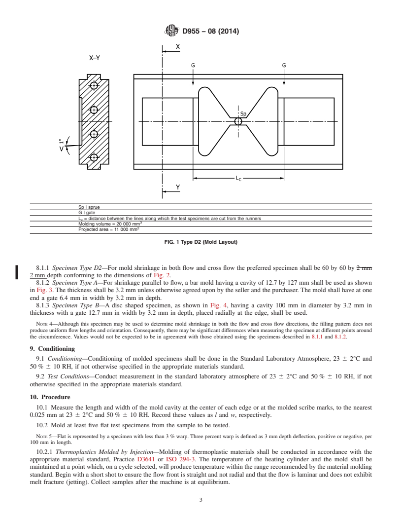
Sp | sprue
G | gate
L = distance between the lines along which the test specimens are cut from the runners
c
Molding volume = 20 000 mm
Projected area = 11 000 mm
FIG. 1 Type D2 (Mold Layout)
D955 − 08 (2014)
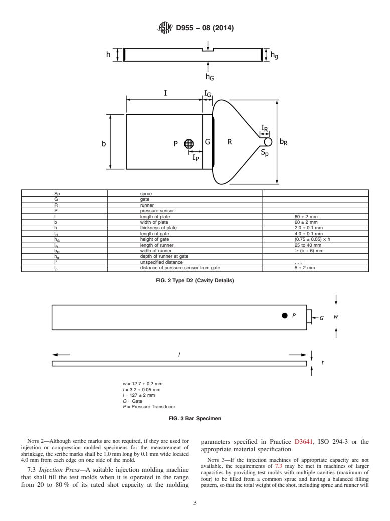
Sp sprue
G gate
R runner
P pressure sensor
l length of plate 60±2mm
b width of plate 60±2mm
h thickness of plate 2.0 ± 0.1 mm
l length of gate 4.0 ± 0.1 mm
G
h height of gate (0.75 ± 0.05) × h
G
l length of runner 25 to 40 mm
R
b width of runner $ (b+6)mm
R
h depth of runner at gate
g
l* unspecified distance . . .
l distance of pressure sensor from gate 5±2mm
p
FIG. 2 Type D2 (Cavity Details)
w = 12.7 ± 0.2 mm
t =3.2±0.05mm
l =127±2mm
G = Gate
P = Pressure Transducer
FIG. 3 Bar Specimen
NOTE 2—Although scribe marks are not required, if they are used for
parameters specified in Practice D3641, ISO 294-3 or the
injection or compression molded specimens for the measurement of
appropriate material specification.
shrinkage,thescribemarksshallbe1.0mmlongby0.1mmwidelocated
NOTE 3—If the injection machines of appropriate capacity are not
4.0 mm from each edge on one side of the mold.
available, the requirements of 7.3 may be met in machines of larger
7.3 Injection Press—A suitable injection molding machine
capacities by providing test molds with multiple cavities (maximum of
that shall fill the test molds when it is operated in the range
four) to be filled from a common sprue and having a balanced filling
from 20 to 80% of its rated shot capacity at the molding pattern,sothatthetotalweightoftheshot,includingsprueandrunnerwill
D955 − 08 (2014)
t =3.2±0.05mm
D =100±2mm
G = Gate
P = Pressure Transducer
FIG. 4 Disk Specimen
fall within the specified limits. there may be significant differences when measuring the specimen at
different points around the circumference. Values would not be expected
7.4 Compression Press—A suitable hydraulic press that
to be in agreement with those obtained using the specimens described in
shall deliver a pressure of 20 to 35 MPa (3000 to 5000 psi) to
8.1.1 and 8.1.2.
the material in the mold.
9. Conditioning
7.5 Measuring Tools—Measuring tools (micrometers, ver-
nier calipers, etc.) accurate to 0.025 mm (0.001 in.) for 9.1 Conditioning—Conditioning of molded specimens shall
bedoneintheStandardLaboratoryAtmosphere,23 62°Cand
measuring the molds and test specimens conforming to the
measuring tool requirements in Test Methods D5947. 50% 6 10 RH, if not otherwise specified in the appropriate
materials standard.
8. Test Specimen
9.2 Test Conditions—Conduct measurement in the standard
8.1 The following specimen dimensions are applicable for
laboratory atmosphere of 23 6 2°C and 50% 6 10 RH, if not
both compression and injection molding. Orientation effects
otherwise specified in the appropriate materials standard.
due to flow direction do not generally pertain to compression
molding. 10. Procedure
8.1.1 Specimen Type D2—For mold shrinkage in both flow
10.1 Measurethelengthandwidthofthemoldcavityatthe
and cross flow the preferred specimen shall be 60 by 60 by
center of each edge or at the molded scribe marks, to the
2mm depth conforming to the dimensions of Fig. 2.
nearest 0.025 mm at 23 6 2°C and 50% 6 10 RH. Record
8.1.2 Specimen TypeA—Forshrinkageparalleltoflow,abar
these values as l and w, respectively.
mold having a cavity of 12.7 by 127 mm shall be used as
10.2 Mold at least five flat test specimens from the sample
shown in Fig. 3. The thickness shall be 3.2 mm unless
to be tested.
otherwise agreed upon by the seller and the purchaser. The
mold shall have at one end a gate 6.4 mm in width by 3.2 mm
NOTE 5—Flat is represented by a specimen with less than 3% warp.
in depth. Three percent warp is defined as 3 mm depth deflection, positive or
negative, per 100 mm in length.
8.1.3 Specimen Type B—Adisc shaped specimen, as shown
in Fig. 4, having a cavity 100 mm in diameter by 3.2 mm in
10.2.1 Thermoplastics Molded by Injection—Molding of
thickness with a gate 12.7 mm in width by 3.2 mm in depth,
thermoplastic materials shall be conducted in accordance with
placed radially at the edge, shall be used.
the appropriate material standard, Practice D3641 or ISO
294-3. The temperature of the heating cylinder and the mold
NOTE 4—Although this specimen may be used to determine mold
shall be maintained at a point which, on a cycle selected, will
shrinkage in both the flow and cross flow directions, the filling pattern
does not produce uniform flow lengths and orientation. Consequently, produce temperature within the range recommended by the
D955 − 08 (2014)
material molding standard. Begin with a short shot to ensure 12.1.1 Tables 1-3 summarize data from a round robin
the flow front is straight and not radial and that the flow is conducted in 1988, using specimens Type A and Type B,
laminar and does not exhibit melt fracture (jetting). Collect involving five thermoplastics materials tested by eight labora-
samples after the machine is at equilibrium. tories. Each material was supplied in granular form to each of
10.2.2 Thermoplastics Molded by Compression—For the testing laboratories by a single supplier. The resins were
thermoplastics,moldingshallbeconductedinaccordancewith handledinaccordancewiththesupplier’sinstructionsandwere
the appropriate material standard or D4703. molded in accordance with Practice D3641. Each test result is
the average of five individual determinations from successive
10.3 Treatment of Specimens after Removal from the Mold:
injection molding cycles. Each laboratory obtained one test
10.3.1 In order to minimize warpage, separate the test
result for each material.
specimens from the runners in the gate area immediately after
removal from the mold. Do not modify or alter the edges used
NOTE 6—A repeatability study was conducted in Europe using speci-
men Type D2. The results, including suggested cavity hold pressure for
for the measurement of dimensions. It is recommended to cool
various materials, are shown in Appendix X1.
specimens in a horizontal position at room temperature by
placing them on a material of low thermal conductivity to 12.1.2 Repeatability estimates S and r were made by
r
minimize warpage. After the first hour, condition the speci- treating the five individual determinations from successive
mens at 23 6 2°C and 50% 6 5 RH, unless otherwise injectionmoldingcyclesastestresults.Poorerprecision(larger
specified in the material standard. valuesof S and r)wouldbeexpectedifthesameoperatorwere
r
10.3.2 Specification of Measurement Time: to shutdown and then restart the injection molding machine on
10.3.2.1 Twentyfourhourshrinkagemeasurementsshallbe the same day with the same mold, material and operating set
made24 60.5hafterthespecimenhasbeenremovedfromthe points. Repeatability under such circumstances was not evalu-
mold. ated.
10.3.2.2 Forty eight hour shrinkage measurements shall be 12.1.3 The following explanations of r and R only are
made48 60.5hafterthespecimenhasbeenremovedfromthe intended to present a meaningful way of considering the
mold. approximate precision of this test method. The data in Tables
1-3 should not be rigorously applied to acceptance or rejected
11. Calculation and Report
of material, as those data are specific to the round robin and
may not be representative of other lots, conditions, materials,
11.1
or laboratories. Users of this test method should apply the
S 5 W 2 W 3100/Wm (1)
~ !
w m s
principlesoutlinedinPracticeE691togeneratedataspe
...
This document is not an ASTM standard and is intended only to provide the user of an ASTM standard an indication of what changes have been made to the previous version. Because
it may not be technically possible to adequately depict all changes accurately, ASTM recommends that users consult prior editions as appropriate. In all cases only the current version
of the standard as published by ASTM is to be considered the official document.
Designation: D955 − 08 D955 − 08 (Reapproved 2014)
Standard Test Method of
Measuring Shrinkage from Mold Dimensions of
Thermoplastics
This standard is issued under the fixed designation D955; the number immediately following the designation indicates the year of
original adoption or, in the case of revision, the year of last revision. A number in parentheses indicates the year of last reapproval. A
superscript epsilon (´) indicates an editorial change since the last revision or reapproval.
This standard has been approved for use by agencies of the U.S. Department of Defense.
1. Scope*Scope
1.1 This test method is intended to measure shrinkage from mold cavity to molded dimensions of thermoplastics when molded
by compression or injection processes with specified process conditions.
1.2 This test method covers shrinkage measurements at 24 and 48 h.hours.
1.3 This method will give comparable data based on standard specimens and can not predict absolute values in actual molded
parts with varying flow paths, wall thicknesses, pressure and temperature gradients and process conditions. Differences in mold
shrinkage may also be observed among the three specimen geometries described in this test method.
1.4 The values stated in SI units are to be regarded as the standard. The values given in parentheses are given for information
only.
1.5 This standard does not purport to address all of the safety concerns, if any, associated with its use. It is the responsibility
of the user of this standard to establish appropriate safety and health practices and determine the applicability of regulatory
limitations prior to use.
NOTE 1—This standard and ISO 294-3 are equivalent in the design of specimen D2. This test method is equivalent to ISO 294-4 where Type D2
specimens and the procedure in Appendix X2 are used.
2. Referenced Documents
2.1 ASTM Standards:
D618 Practice for Conditioning Plastics for Testing
D788 Classification System for Poly(Methyl Methacrylate) (PMMA) Molding and Extrusion Compounds
D883 Terminology Relating to Plastics
D3641 Practice for Injection Molding Test Specimens of Thermoplastic Molding and Extrusion Materials
D4066 Classification System for Nylon Injection and Extrusion Materials (PA)
D4549 Classification System and Basis for Specification for Polystyrene and Rubber-Modified Polystyrene Molding and
Extrusion Materials (PS)
D4703 Practice for Compression Molding Thermoplastic Materials into Test Specimens, Plaques, or Sheets
D4976 Specification for Polyethylene Plastics Molding and Extrusion Materials
D5947 Test Methods for Physical Dimensions of Solid Plastics Specimens
D6778 Classification System and Basis for Specification for Polyoxymethylene Molding and Extrusion Materials (POM)
D6779 Classification System for and Basis of Specification for Polyamide Molding and Extrusion Materials (PA)
E691 Practice for Conducting an Interlaboratory Study to Determine the Precision of a Test Method
2.2 ISO Standards:
ISO 293 Plastics—Compression Moulding Test Specimens of Thermoplastic Materials
ISO 294-1 Plastics—Injection Moulding of Test Specimens of Thermoplastic Materials—Part 1: General Principles, and
Moulding of Multipurpose and Bar Test specimens
This test method is under the jurisdiction of ASTM Committee D20 on Plastics and is the direct responsibility of Subcommittee D20.09 on Specimen Preparation.
Current edition approved Nov. 1, 2008Aug. 1, 2014. Published December 2008August 2014. Originally approved in 1948. Last previous edition approved in 20002008
as D955 - 00.D955 - 08. DOI: 10.1520/D0955-08.10.1520/D0955-08R14.
For referenced ASTM standards, visit the ASTM website, www.astm.org, or contact ASTM Customer Service at service@astm.org. For Annual Book of ASTM Standards
volume information, refer to the standard’s Document Summary page on the ASTM website.
Available from American National Standards Institute (ANSI), 25 W. 43rd St., 4th Floor, New York, NY 10036, http://www.ansi.org.
*A Summary of Changes section appears at the end of this standard
Copyright © ASTM International, 100 Barr Harbor Drive, PO Box C700, West Conshohocken, PA 19428-2959. United States
D955 − 08 (2014)
ISO 294-3 Plastics—Injection Moulding of Test Specimens of Thermoplastic Materials—Part 3: Small Plates
ISO 294-4 Plastics—Injection Moulding of Test Specimens—Part 4: Determination of Moulding Shrinkage
3. Terminology
3.1 Definitions—General definitions of terms applying to this test method appear in Terminology D883.
3.2 Definitions of Terms Specific to This Standard:
3.2.1 jetting, n—non-uniform multi-directional flow front apparent on the surface of the mold due to rapid filling of the mold
cavity.
4. Summary of Test Method
4.1 The principle of this test method is to compare mold cavity dimensions with specimen dimensions and report the differences
in percent.
5. Significance and Use
5.1 Injection Molding—In injection molding, the difference between the dimensions of a mold cavity and of the molded
specimen may vary according to the design of the mold and operation of the molding process. Factors such as mold and melt
temperature, fill times, and packing conditions are known to affect shrinkage significantly. Adherence to the specified mold design
(see 7.1) and specifications outlined in Practice D3641 or ISO 294-4 or the appropriate material specification will improve the
reproducibility of the test.
5.2 Compression Molding—In compression molding, the difference between the dimensions of a mold cavity and of the molded
specimen may vary according to the design of the mold and operation of the molding process. Factors, such as the amount of
material in charge, cooling time, and pressure application are known to affect shrinkage significantly. Adherence to the specified
mold design (see 7.2) and specifications outlined in Practice D4703 or ISO 293 or the appropriate material specifications will
improve the reproducibility of the test.
6. Sample Preparation
6.1 Some materials require special treatment before they are molded. For example, thermoplastics, which absorb moisture must
be dried before molding. For required conditions for sample preparation, refer to the appropriate material specification or the
manufacturer’s recommendations if no specification is available. The preparation given to the material prior to molding shall be
recorded and reported.
7. Apparatus
7.1 Injection Mold—Specimens shall be molded in a two cavity mold conforming with dimensions as shown in Figs. 1 and 2
for the 60 × 60-mm plaque specimen (Type D2), Fig. 3 for the 12.7 by 127-mm bar specimen (Type A) and Fig. 4 for the 100 mm
by 3.2-mm disk specimen (Type B). Pressure transducers for monitoring the pressure in at least one cavity are mandatory for Type
D2. Mold shrinkage measurements shall be made on specimens that have been molded at one of the following cavity pressures
6 3 % from the selected pressure: 20 MPa, 40 MPa, 60 MPa, 80 MPa, 100 MPa, or as specified in the appropriate material
specification. Pressure transducers are recommended, but not mandatory for specimens Type A and Type B.
7.2 Compression Mold—A single cavity positive mold having cavity dimensions conforming to the dimensions of Fig. 2 for the
60 × 60-mm plaque (Type D2) Fig. 3 for the 12.7 × 127-mm bar specimen (Type A) and Fig. 4 for the 100-mm × 3.2-mm disk
specimen (Type B), not including the sprue, runner or gate.
NOTE 2—Although scribe marks are not required, if they are used for injection or compression molded specimens for the measurement of shrinkage,
the scribe marks shall be 1.0 mm long by 0.1 mm wide located 4.0 mm from each edge on one side of the mold.
7.3 Injection Press—A suitable injection molding machine that shall fill the test molds when it is operated in the range from
20 to 80 % of its rated shot capacity at the molding parameters specified in Practice D3641, ISO 294-3 or the appropriate material
specification.
NOTE 3—If the injection machines of appropriate capacity are not available, the requirements of 7.3 may be met in machines of larger capacities by
providing test molds with multiple cavities (maximum of four) to be filled from a common sprue and having a balanced filling pattern, so that the total
weight of the shot, including sprue and runner will fall within the specified limits.
7.4 Compression Press—A suitable hydraulic press that shall deliver a pressure of 20 to 35 MPa (3000 to 5000 psi) to the
material in the mold.
7.5 Measuring Tools—Measuring tools (micrometers, vernier calipers, etc.) accurate to 0.025 mm (0.001 in.) for measuring the
molds and test specimens conforming to the measuring tool requirements in Test Methods D5947.
8. Test Specimen
8.1 The following specimen dimensions are applicable for both compression and injection molding. Orientation effects due to
flow direction do not generally pertain to compression molding.
D955 − 08 (2014)
Sp | sprue
G | gate
L = distance between the lines along which the test specimens are cut from the runners
c
Molding volume = 20 000 mm
Projected area = 11 000 mm
FIG. 1 Type D2 (Mold Layout)
8.1.1 Specimen Type D2—For mold shrinkage in both flow and cross flow the preferred specimen shall be 60 by 60 by 2 mm
2 mm depth conforming to the dimensions of Fig. 2.
8.1.2 Specimen Type A—For shrinkage parallel to flow, a bar mold having a cavity of 12.7 by 127 mm shall be used as shown
in Fig. 3. The thickness shall be 3.2 mm unless otherwise agreed upon by the seller and the purchaser. The mold shall have at one
end a gate 6.4 mm in width by 3.2 mm in depth.
8.1.3 Specimen Type B—A disc shaped specimen, as shown in Fig. 4, having a cavity 100 mm in diameter by 3.2 mm in
thickness with a gate 12.7 mm in width by 3.2 mm in depth, placed radially at the edge, shall be used.
NOTE 4—Although this specimen may be used to determine mold shrinkage in both the flow and cross flow directions, the filling pattern does not
produce uniform flow lengths and orientation. Consequently, there may be significant differences when measuring the specimen at different points around
the circumference. Values would not be expected to be in agreement with those obtained using the specimens described in 8.1.1 and 8.1.2.
9. Conditioning
9.1 Conditioning—Conditioning of molded specimens shall be done in the Standard Laboratory Atmosphere, 23 6 2°C and
50 % 6 10 RH, if not otherwise specified in the appropriate materials standard.
9.2 Test Conditions—Conduct measurement in the standard laboratory atmosphere of 23 6 2°C and 50 % 6 10 RH, if not
otherwise specified in the appropriate materials standard.
10. Procedure
10.1 Measure the length and width of the mold cavity at the center of each edge or at the molded scribe marks, to the nearest
0.025 mm at 23 6 2°C and 50 % 6 10 RH. Record these values as l and w, respectively.
10.2 Mold at least five flat test specimens from the sample to be tested.
NOTE 5—Flat is represented by a specimen with less than 3 % warp. Three percent warp is defined as 3 mm depth deflection, positive or negative, per
100 mm in length.
10.2.1 Thermoplastics Molded by Injection—Molding of thermoplastic materials shall be conducted in accordance with the
appropriate material standard, Practice D3641 or ISO 294-3. The temperature of the heating cylinder and the mold shall be
maintained at a point which, on a cycle selected, will produce temperature within the range recommended by the material molding
standard. Begin with a short shot to ensure the flow front is straight and not radial and that the flow is laminar and does not exhibit
melt fracture (jetting). Collect samples after the machine is at equilibrium.
D955 − 08 (2014)
Sp sprue
G gate
R runner
P pressure sensor
l length of plate 60 ± 2 mm
b width of plate 60 ± 2 mm
h thickness of plate 2.0 ± 0.1 mm
l length of gate 4.0 ± 0.1 mm
G
h height of gate (0.75 ± 0.05) × h
G
l length of runner 25 to 40 mm
R
b width of runner $ (b + 6) mm
R
h depth of runner at gate
g
l* unspecified distance . . .
l distance of pressure sensor from gate 5 ± 2 mm
p
FIG. 2 Type D2 (Cavity Details)
w = 12.7 ± 0.2 mm
t = 3.2 ± 0.05 mm
l = 127 ± 2 mm
G = Gate
P = Pressure Transducer
FIG. 3 Bar Specimen
10.2.2 Thermoplastics Molded by Compression—For thermoplastics, molding shall be conducted in accordance with the
appropriate material standard or D4703.
10.3 Treatment of Specimens after Removal from the Mold:
10.3.1 In order to minimize warpage, separate the test specimens from the runners in the gate area immediately after removal
from the mold. Do not modify or alter the edges used for the measurement of dimensions. It is recommended to cool specimens
in a horizontal position at room temperature by placing them on a material of low thermal conductivity to minimize warpage. After
the first hour, condition the specimens at 23 6 2°C and 50 % 6 5 RH, unless otherwise specified in the material standard.
D955 − 08 (2014)
t = 3.2 ± 0.05 mm
D = 100 ± 2 mm
G = Gate
P = Pressure Transducer
FIG. 4 Disk Specimen
10.3.2 Specification of Measurement Time:
10.3.2.1 Twenty four hour shrinkage measurements shall be made 24 6 0.5 h after the specimen has been removed from the
mold.
10.3.2.2 Forty eight hour shrinkage measurements shall be made 48 6 0.5 h after the specimen has been removed from the
mold.
11. Calculation and Report
11.1
S 5 W 2 W 3100/Wm (1)
~ !
w m s
where:
S = the shrinkage perpendicular to flow, %,
w
W = the mold dimension perpendicular to flow,
m
W = the specimen dimension perpendicular to flow, and
s
S 5 L 2 L 3100/Lm (2)
~ !
1 m s
where:
S = the shrinkage parallel to flow, %,
L = the mold dimension parallel to flow, and,
m
L = the specimen dimension parallel to flow.
s
Report mold shrinkage in both flow and cross direction to two significant figures.
11.2 The report shall include the following:
11.2.1 Details of any special material preparation, such as drying, which the material received before molding;
11.2.2 The molding procedure used, following the report as outlined in Practice D3641 for injection molding and Practice
D4703 for compression molding.
11.2.3 The 24-hour shrinkage and the 48-hour shrinkage shall be expressed in percent (mm/mm) with each value representing
the mean of determinations obtained on five or more specimens.
12. Precision and Bias
12.1 Precision:
D955 − 08 (2014)
12.1.1 Tables
...
Questions, Comments and Discussion
Ask us and Technical Secretary will try to provide an answer. You can facilitate discussion about the standard in here.