


ASTM F821/F821M-01(2018)
(Specification)Standard Specification for Domestic Use Doors and Frames, Steel, Interior, Marine
Standard Specification for Domestic Use Doors and Frames, Steel, Interior, Marine
ABSTRACT
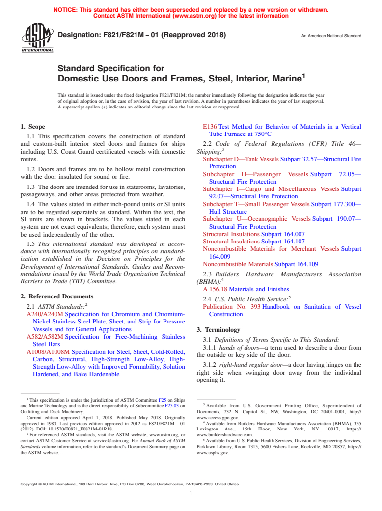
This specification covers the design and dimensional requirements for the construction of standard and custom-built interior steel doors and frames intended for use in staterooms, lavatories, passageways, and other weather-protected areas of ships, including U.S. Coast Guard certificated vessels, with domestic routes. The doors and frames are to be of hollow metal construction with the door insulated for sound or fire. The doors and frames shall conform to the specified dimensional and construction procedures established for each class and type, which shall be indicated in the ordering information.
SCOPE
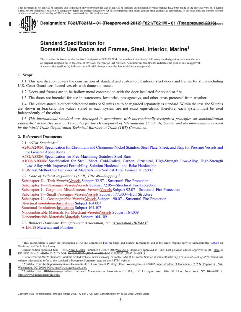
1.1 This specification covers the construction of standard and custom-built interior steel doors and frames for ships including U.S. Coast Guard certificated vessels with domestic routes.
1.2 Doors and frames are to be hollow metal construction with the door insulated for sound or fire.
1.3 The doors are intended for use in staterooms, lavatories, passageways, and other areas protected from weather.
1.4 The values stated in either inch-pound units or SI units are to be regarded separately as standard. Within the text, the SI units are shown in brackets. The values stated in each system are not exact equivalents; therefore, each system must be used independently of the other.
1.5 This international standard was developed in accordance with internationally recognized principles on standardization established in the Decision on Principles for the Development of International Standards, Guides and Recommendations issued by the World Trade Organization Technical Barriers to Trade (TBT) Committee.
General Information
Buy Standard
Standards Content (Sample)
NOTICE: This standard has either been superseded and replaced by a new version or withdrawn.
Contact ASTM International (www.astm.org) for the latest information
Designation: F821/F821M − 01 (Reapproved 2018) An American National Standard
Standard Specification for
Domestic Use Doors and Frames, Steel, Interior, Marine
This standard is issued under the fixed designation F821/F821M; the number immediately following the designation indicates the year
of original adoption or, in the case of revision, the year of last revision. A number in parentheses indicates the year of last reapproval.
A superscript epsilon (´) indicates an editorial change since the last revision or reapproval.
1. Scope E136 Test Method for Behavior of Materials in a Vertical
Tube Furnace at 750°C
1.1 This specification covers the construction of standard
and custom-built interior steel doors and frames for ships 2.2 Code of Federal Regulations (CFR) Title 46—
including U.S. Coast Guard certificated vessels with domestic Shipping:
routes. Subchapter D—Tank Vessels Subpart 32.57—Structural Fire
Protection
1.2 Doors and frames are to be hollow metal construction
Subchapter H—Passenger Vessels Subpart 72.05—
with the door insulated for sound or fire.
Structural Fire Protection
1.3 The doors are intended for use in staterooms, lavatories,
Subchapter I—Cargo and Miscellaneous Vessels Subpart
passageways, and other areas protected from weather.
92.07—Structural Fire Protection
Subchapter T—Small Passenger Vessels Subpart 177.300—
1.4 The values stated in either inch-pound units or SI units
are to be regarded separately as standard. Within the text, the Hull Structure
Subchapter U—Oceanographic Vessels Subpart 190.07—
SI units are shown in brackets. The values stated in each
system are not exact equivalents; therefore, each system must Structural Fire Protection
Structural Insulations Subpart 164.007
be used independently of the other.
Structural Insulations Subpart 164.107
1.5 This international standard was developed in accor-
Noncombustible Materials for Merchant Vessels Subpart
dance with internationally recognized principles on standard-
164.009
ization established in the Decision on Principles for the
Noncombustible Materials Subpart 164.109
Development of International Standards, Guides and Recom-
mendations issued by the World Trade Organization Technical 2.3 Builders Hardware Manufacturers Association
Barriers to Trade (TBT) Committee. (BHMA):
A 156.18 Materials and Finishes
2. Referenced Documents 5
2.4 U.S. Public Health Service:
2.1 ASTM Standards: Publication No. 393 Handbook on Sanitation of Vessel
A240/A240M Specification for Chromium and Chromium- Construction
Nickel Stainless Steel Plate, Sheet, and Strip for Pressure
Vessels and for General Applications 3. Terminology
A582/A582M Specification for Free-Machining Stainless
3.1 Definitions of Terms Specific to This Standard:
Steel Bars
3.1.1 hands of doors—a term used to describe a door from
A1008/A1008M Specification for Steel, Sheet, Cold-Rolled,
the outside or key side of the door.
Carbon, Structural, High-Strength Low-Alloy, High-
3.1.2 right-hand regular door—a door having hinges on the
Strength Low-Alloy with Improved Formability, Solution
right side when swinging door away from the individual
Hardened, and Bake Hardenable
opening it.
This specification is under the jurisdiction of ASTM Committee F25 on Ships
and Marine Technology and is the direct responsibility of Subcommittee F25.03 on Available from U.S. Government Printing Office, Superintendent of
Outfitting and Deck Machinery. Documents, 732 N. Capitol St., NW, Washington, DC 20401-0001, http://
Current edition approved April 1, 2018. Published May 2018. Originally www.access.gpo.gov.
approved in 1983. Last previous edition approved in 2012 as F821/F821M – 01 Available from Builders Hardware Manufacturers Association (BHMA), 355
(2012). DOI: 10.1520/F0821_F0821M-01R18. Lexington Ave., 15th Floor, New York, NY 10017, https://
For referenced ASTM standards, visit the ASTM website, www.astm.org, or www.buildershardware.com.
contact ASTM Customer Service at service@astm.org. For Annual Book of ASTM Available from U.S. Public Health Services, Division of Engineering Services,
Standards volume information, refer to the standard’s Document Summary page on Parklawn Library, Room 1315, 5600 Fishers Lane, Rockville, MD 20857, https://
the ASTM website. www.usphs.gov.
Copyright © ASTM International, 100 Barr Harbor Drive, PO Box C700, West Conshohocken, PA 19428-2959. United States
F821/F821M − 01 (2018)
3.1.3 left-hand regular door—a door having hinges on the 5. Ordering Information
left side when swinging door away from the individual opening
5.1 Orders for items under this specification shall include
it.
the following information by the purchaser:
3.1.4 right-hand reverse bevel door—a door having hinges
5.1.1 Class A-O, A, B, or C.
on right side when swinging door towards the individual
5.1.2 Type, hand, clear jamb width, and sill height.
opening it.
5.1.3 Options such as vent grills, louvers, vision lights, and
hose ports.
3.1.5 left-hand reverse bevel door—a door having hinges on
5.1.4 Hardware, sill caps, lock sets, latches, door closers,
left side when swinging door towards the individual opening it.
and hold backs if other than manufacturer’s standard. Master
3.1.6 face plates—the exterior metal skins that enclose the
keying of door locks will not be provided unless required and
internal supporting structure of the door.
defined by ordering documents. Instead, each door lock will be
3.1.7 latch—a device normally installed in the vertical edge
keyed differently.
of door, opposite hinge edge, that when latched retains door in
5.1.5 Color chip and desired painting specifications or other
closed position.
commercial designation for final finish. If not specified, doors
3.1.8 throw—the extension, or reach, of the latch bolt. This will have manufacturer’s prime coat applied.
throw is measured from latch face plate to extreme outer edge
5.1.6 For Type II and III doors, sizes and any other
of latch bolt with latch bolt in fully extended position. supplementary requirements.
5.1.7 Sill Heights—0 in. (0 mm), 1 ⁄2 in. (38 mm), or 6 in.
3.1.9 padlock eye—a means for securing door in closed
(152 mm). See Figs. 1-3.
position by the use of a padlock.
5.1.8 Cut out for light switch; if not requested in ordering
data, no provisions will be made.
4. Classification
4.1 Classes of doors and frames shall be as indicated in the
6. Materials and Manufacture
ordering information. (See Annex A1 for definition of various
6.1 For typical design, see Figs. 1-3.
class divisions.)
4.1.1 Class A-O for installation in Class A-O divisions.
6.2 Steel for doors and frames shall be cold-rolled sheet,
4.1.2 Class A for installation in Class A-15, A-30, and A-60
commercial quality in accordance with Specification A1008/
divisions.
A1008M. Other materials shall be as indicated.
4.1.3 Class B for installation in Class B divisions.
6.3 Class A-O Doors (See Fig. 1 and Table 1 and Table 2):
4.1.4 Class C for installation in Class C divisions.
6.3.1 Door shall be 1 ⁄4-in. (45-mm) thick hollow steel with
4.2 Doors and frames shall be of the following types as
0.055-in. (1.4-mm) minimum face plates or equivalent metal
indicated in ordering information.
construction.
4.2.1 Type I standard doors are of the following widths. 3
6.3.2 Doors shall have a latch with a minimum throw of ⁄4
Height and details shall conform to Tables 1-6 and Figs. 1-3.
in. (19 mm).
Size 1—22-in. (559-mm) clear jamb width
6.3.3 Door frames shall be of steel with a nominal thickness
Size 2—24-in. (610-mm) clear jamb width
of 0.055 in. (1.4 mm) and shall be installed so that any flame
Size 3—26-in. (660-mm) clear jamb width
penetration would be through at least two thicknesses of 0.055
Size 4—30-in. (762-mm) clear jamb width
in. (1.4 mm) or equivalent.
Size 5—36-in. (914-mm) clear jamb width 5
6.3.4 Door frames shall provide a stop of ⁄8 in. (16 mm)
4.2.2 Type II doors conforming generally to specifications
minimum at the sides and top.
but requiring special requirements as indicated in the ordering
6.3.5 For undercut at bottom of door, see Fig. 1 and Table 2.
information (see also 6.7.9).
6.3.6 Doors other than those that are normally locked shall
4.2.3 Type III double doors using two of Type I doors.
be self closing and capable of closing against a 3½° list.
4.2.4 Type IV double doors using two of Type II doors.
6.3.7 Doors shall be insulated with sufficient noncombus-
1 tible fibrous insulation to sound dampen the door adequately.
NOTE 1—Door widths are approximately 1 ⁄4 in. (approximately 32
mm) greater than clear jamb width. This insulation shall be selected from those listed under
TABLE 1 Class A-O and Class A Door Dimension
Table of Dimensions—Door
Designation in. mm
Thickness A 1 ⁄4 45
Clear height from structural deck B 78 ⁄2 1994
Clear height from finished deck C approximately 78 approximately 1981
Height from structural deck to center line of vision light D 64 1626
Height from structural deck to center line of cutout for switch E 48 1219
Height from structural deck to center line of knob F 38 965
Undercut G see Table 2 see Table 2
Sill height H see Table 2 see Table 2
F821/F821M − 01 (2018)
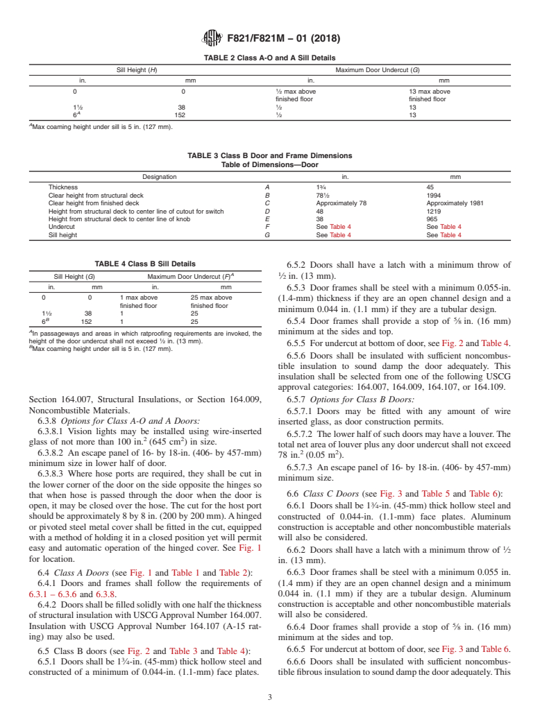
TABLE 2 Class A-O and A Sill Details
Sill Height (H) Maximum Door Undercut (G)
in. mm in. mm
0 0 ⁄2 max above 13 max above
finished floor finished floor
1 1
1 ⁄2 38 ⁄2 13
A
6 152 ⁄2 13
A
Max coaming height under sill is 5 in. (127 mm).
TABLE 3 Class B Door and Frame Dimensions
Table of Dimensions—Door
Designation in. mm
Thickness A 1 ⁄4 45
Clear height from structural deck B 78 ⁄2 1994
Clear height from finished deck C Approximately 78 Approximately 1981
Height from structural deck to center line of cutout for switch D 48 1219
Height from structural deck to center line of knob E 38 965
Undercut F See Table 4 See Table 4
Sill height G See Table 4 See Table 4
TABLE 4 Class B Sill Details
6.5.2 Doors shall have a latch with a minimum throw of
A 1
Sill Height (G) Maximum Door Undercut (F) ⁄2 in. (13 mm).
in. mm in. mm
6.5.3 Door frames shall be steel with a minimum 0.055-in.
0 0 1 max above 25 max above
(1.4-mm) thickness if they are an open channel design and a
finished floor finished floor
minimum 0.044 in. (1.1 mm) if they are a tubular design.
1 ⁄2 38 1 25
B 5
6 152 1 25
6.5.4 Door frames shall provide a stop of ⁄8 in. (16 mm)
A
minimum at the sides and top.
In passageways and areas in which ratproofing requirements are invoked, the
height of the door undercut shall not exceed ⁄2 in. (13 mm).
6.5.5 For undercut at bottom of door, see Fig. 2 and Table 4.
B
Max coaming height under sill is 5 in. (127 mm).
6.5.6 Doors shall be insulated with sufficient noncombus-
tible insulation to sound damp the door adequately. This
insulation shall be selected from one of the following USCG
approval categories: 164.007, 164.009, 164.107, or 164.109.
6.5.7 Options for Class B Doors:
Section 164.007, Structural Insulations, or Section 164.009,
Noncombustible Materials.
6.5.7.1 Doors may be fitted with any amount of wire
6.3.8 Options for Class A-O and A Doors:
inserted glass, as door construction permits.
6.3.8.1 Vision lights may be installed using wire-inserted
6.5.7.2 The lower half of such doors may have a louver. The
2 2
glass of not more than 100 in. (645 cm ) in size.
total net area of louver plus any door undercut shall not exceed
2 2
6.3.8.2 An escape panel of 16- by 18-in. (406- by 457-mm)
78 in. (0.05 m ).
minimum size in lower half of door.
6.5.7.3 An escape panel of 16- by 18-in. (406- by 457-mm)
6.3.8.3 Where hose ports are required, they shall be cut in
minimum size.
the lower corner of the door on the side opposite the hinges so
6.6 Class C Doors (see Fig. 3 and Table 5 and Table 6):
that when hose is passed through the door when the door is
open, it may be closed over the hose. The cut for the host port
6.6.1 Doors shall be 1 ⁄4-in. (45-mm) thick hollow steel and
should be approximately 8 by 8 in. (200 by 200 mm). A hinged constructed of 0.044-in. (1.1-mm) face plates. Aluminum
or pivoted steel metal cover shall be fitted in the cut, equipped construction is acceptable and other noncombustible materials
with a method of holding it in a closed position yet will permit will also be considered.
easy and automatic operation of the hinged cover. See Fig. 1
6.6.2 Doors shall have a latch with a minimum throw of ⁄2
for location.
in. (13 mm).
6.4 Class A Doors (see Fig. 1 and Table 1 and Table 2): 6.6.3 Door frames shall be steel with a minimum 0.055 in.
(1.4 mm) if they are an open channel design and a minimum
6.4.1 Doors and frames shall follow the requirements of
6.3.1 – 6.3.6 and 6.3.8. 0.044 in. (1.1 mm) if they are a tubular design. Aluminum
construction is acceptable and other noncombustible materials
6.4.2 Doors shall be filled solidly with one half the thickness
will also be considered.
of structural insulation with USCG Approval Number 164.007.
Insulation with USCG Approval Number 164.107 (A-15 rat-
6.6.4 Door frames shall provide a stop of ⁄8 in. (16 mm)
ing) may also be used.
minimum at the sides and top.
6.6.5 For undercut at bottom of door, see Fig. 3 and Table 6.
6.5 Class B doors (see Fig. 2 and Table 3 and Table 4):
6.5.1 Doors shall be 1 ⁄4-in. (45-mm) thick hollow steel and 6.6.6 Doors shall be insulated with sufficient noncombus-
constructed of a minimum of 0.044-in. (1.1-mm) face plates. tible fibrous insulation to sound damp the door adequately. This
F821/F821M − 01 (2018)
TABLE 5 Class C Door Dimensions
Designation in. mm
Thickness A 1 ⁄4 45
1 Clear height from structural deck B 78 ⁄2 1994
Clear height from finished deck C Approximately 78 Approximately 1981
Height from structural deck to center line of cutout for switch D 48 1219
Height from structural deck to center line of padlock eye E 46 1168
Height from structural deck to center line of knob F 38 965
Undercut G See Table 6 See Table 6
Sill height H See Table 6 See Table 6
TABLE 6 Class C Sill Details
A
Sill Height (H) Maximum Door Undercut (G)
in. mm in. mm
0 0 1 max above 25 max above
finished floor finished floor
1 ⁄2 38 1 25
B
6 152 1 25
A
In passageways and areas in which ratproofing requirements are invoked, the
height of the door undercut shall not exceed ⁄2 in. (13 mm).
B
Max coaming height under sill is 5 in. (127 mm).
NOTE 1—For Class B door requirements, see 6.5.
FIG. 2 Class “B” Door and Frame
NOTE 1—For Class A-O and Class A door requirements, see 6.3 and 6.4,
respectively.
FIG. 1 Class A-O and Class A Door and Frame
insulation shall be selected from those listed in the Section
164.007, Structural Insulations, or Section 164.009, Noncom-
bustible Materials.
6.6.7 Options for Class C Doors:
...
This document is not an ASTM standard and is intended only to provide the user of an ASTM standard an indication of what changes have been made to the previous version. Because
it may not be technically possible to adequately depict all changes accurately, ASTM recommends that users consult prior editions as appropriate. In all cases only the current version
of the standard as published by ASTM is to be considered the official document.
Designation: F821/F821M − 01 (Reapproved 2012) F821/F821M − 01 (ReapprovedAn American National2018)Standard
Standard Specification for
Domestic Use Doors and Frames, Steel, Interior, Marine
This standard is issued under the fixed designation F821/F821M; the number immediately following the designation indicates the year
of original adoption or, in the case of revision, the year of last revision. A number in parentheses indicates the year of last reapproval.
A superscript epsilon (´) indicates an editorial change since the last revision or reapproval.
1. Scope
1.1 This specification covers the construction of standard and custom-built interior steel doors and frames for ships including
U.S. Coast Guard certificated vessels with domestic routes.
1.2 Doors and frames are to be hollow metal construction with the door insulated for sound or fire.
1.3 The doors are intended for use in staterooms, lavatories, passageways, and other areas protected from weather.
1.4 The values stated in either inch-pound units or SI units are to be regarded separately as standard. Within the text, the SI units
are shown in brackets. The values stated in each system are not exact equivalents; therefore, each system must be used
independently of the other.
1.5 This international standard was developed in accordance with internationally recognized principles on standardization
established in the Decision on Principles for the Development of International Standards, Guides and Recommendations issued
by the World Trade Organization Technical Barriers to Trade (TBT) Committee.
2. Referenced Documents
2.1 ASTM Standards:
A240/A240M Specification for Chromium and Chromium-Nickel Stainless Steel Plate, Sheet, and Strip for Pressure Vessels and
for General Applications
A582/A582M Specification for Free-Machining Stainless Steel Bars
A1008/A1008M Specification for Steel, Sheet, Cold-Rolled, Carbon, Structural, High-Strength Low-Alloy, High-Strength
Low-Alloy with Improved Formability, Solution Hardened, and Bake Hardenable
E136 Test Method for Behavior of Materials in a Vertical Tube Furnace at 750°C
2.2 Code of Federal Regulations (CFR) Title 46—Shipping:
Subchapter D—Tank Vessels,Vessels Subpart 32.57—Structural Fire Protection
Subchapter H—Passenger Vessels,Vessels Subpart 72.05—Structural Fire Protection
Subchapter I—Cargo and Miscellaneous Vessels,Vessels Subpart 92.07—Structural Fire Protection
Subchapter T—Small Passenger Vessels,Vessels Subpart 177.300—Hull Structure
Subchapter U—Oceanographic Vessels,Vessels Subpart 190.07—Structural Fire Protection
Structural Insulations,Insulations Subpart 164.007
Structural Insulations,Insulations Subpart 164.107
Noncombustible Materials for Merchant Vessels,Vessels Subpart 164.009
Noncombustible Materials,Materials Subpart 164.109
2.3 Builders Hardware Manufacturers Association, Inc.:Association (BHMA):
A 156.18 Materials and Finishes
This specification is under the jurisdiction of ASTM Committee F25 on Ships and Marine Technology and is the direct responsibility of Subcommittee F25.03 on
Outfitting and Deck Machinery.
Current edition approved June 1, 2012April 1, 2018. Published October 2012May 2018. Originally approved in 1983. Last previous edition approved in 20012012 as
ε1
F821/F821M – 01 (2007)(2012). . DOI: 10.1520/F0821_F0821M-01R12.10.1520/F0821_F0821M-01R18.
For referenced ASTM standards, visit the ASTM website, www.astm.org, or contact ASTM Customer Service at service@astm.org. For Annual Book of ASTM Standards
volume information, refer to the standard’s Document Summary page on the ASTM website.
Available from the Superintendent of Documents, U.S. Government Printing Office, Washington, DC 20402.Superintendent of Documents, 732 N. Capitol St., NW,
Washington, DC 20401-0001, http://www.access.gpo.gov.
Available from BHMA, Inc., Builders Hardware Manufacturers Association (BHMA), 355 Lexington Ave., 17th15th Floor, New York, NY 10017.10017,
https://www.buildershardware.com.
Copyright © ASTM International, 100 Barr Harbor Drive, PO Box C700, West Conshohocken, PA 19428-2959. United States
F821/F821M − 01 (2018)
2.4 U.S. Public Health Service:
Publication No. 393,393 Handbook on Sanitation of Vessel Construction
3. Terminology
3.1 Definitions of Terms Specific to This Standard:
3.1.1 hands of doors—a term used to describe a door from the outside or key side of the door.
3.1.2 right-hand regular door—a door having hinges on the right side when swinging door away from the individual opening
it.
3.1.3 left-hand regular door—a door having hinges on the left side when swinging door away from the individual opening it.
3.1.4 right-hand reverse bevel door—a door having hinges on right side when swinging door towards the individual opening
it.
3.1.5 left-hand reverse bevel door—a door having hinges on left side when swinging door towards the individual opening it.
3.1.6 face plates—the exterior metal skins that enclose the internal supporting structure of the door.
3.1.7 latch—a device normally installed in the vertical edge of door, opposite hinge edge, that when latched retains door in
closed position.
3.1.8 throw—the extension, or reach, of the latch bolt. This throw is measured from latch face plate to extreme outer edge of
latch bolt with latch bolt in fully extended position.
3.1.9 padlock eye—a means for securing door in closed position by the use of a padlock.
4. Classification
4.1 Classes of doors and frames shall be as indicated in the ordering information. (See Annex A1 for definition of various class
divisions.)
4.1.1 Class A-O for installation in Class A-O divisions.
4.1.2 Class A for installation in Class A-15, A-30, and A-60 divisions.
4.1.3 Class B for installation in Class B divisions.
4.1.4 Class C for installation in Class C divisions.
4.2 Doors and frames shall be of the following types as indicated in ordering information.
4.2.1 Type I standard doors are of the following widths. Height and details shall conform to Tables 1-6 and Figs. 1-3.
Size 1—22-in. (559-mm) clear jamb width
Size 2—24-in. (610-mm) clear jamb width
Size 3—26-in. (660-mm) clear jamb width
Size 4—30-in. (762-mm) clear jamb width
Size 5—36-in. (914-mm) clear jamb width
4.2.2 Type II doors conforming generally to specifications but requiring special requirements as indicated in the ordering
information (see also 6.7.9).
4.2.3 Type III double doors using two of Type I doors.
4.2.4 Type IV double doors using two of Type II doors.
NOTE 1—Door widths are approximately 1 ⁄4 in. (approximately 32 mm) greater than clear jamb width.
TABLE 1 Class A-O and Class A Door Dimension
Table of Dimensions—Door
Designation in. mm
Thickness A 1 ⁄4 45
Clear height from structural deck B 78 ⁄2 1994
Clear height from finished deck C approximately 78 approximately 1981
Height from structural deck to center line of vision light D 64 1626
Height from structural deck to center line of cutout for switch E 48 1219
Height from structural deck to center line of knob F 38 965
Undercut G see Table 2 see Table 2
Sill height H see Table 2 see Table 2
Available from United States U.S. Public Health Services, Division of Engineering Services, Parklawn Library, Room 1315, 5600 Fishers Lane, Rockville, MD 20857,
Attention: Ms. Bonnie Scott.https://www.usphs.gov.
F821/F821M − 01 (2018)
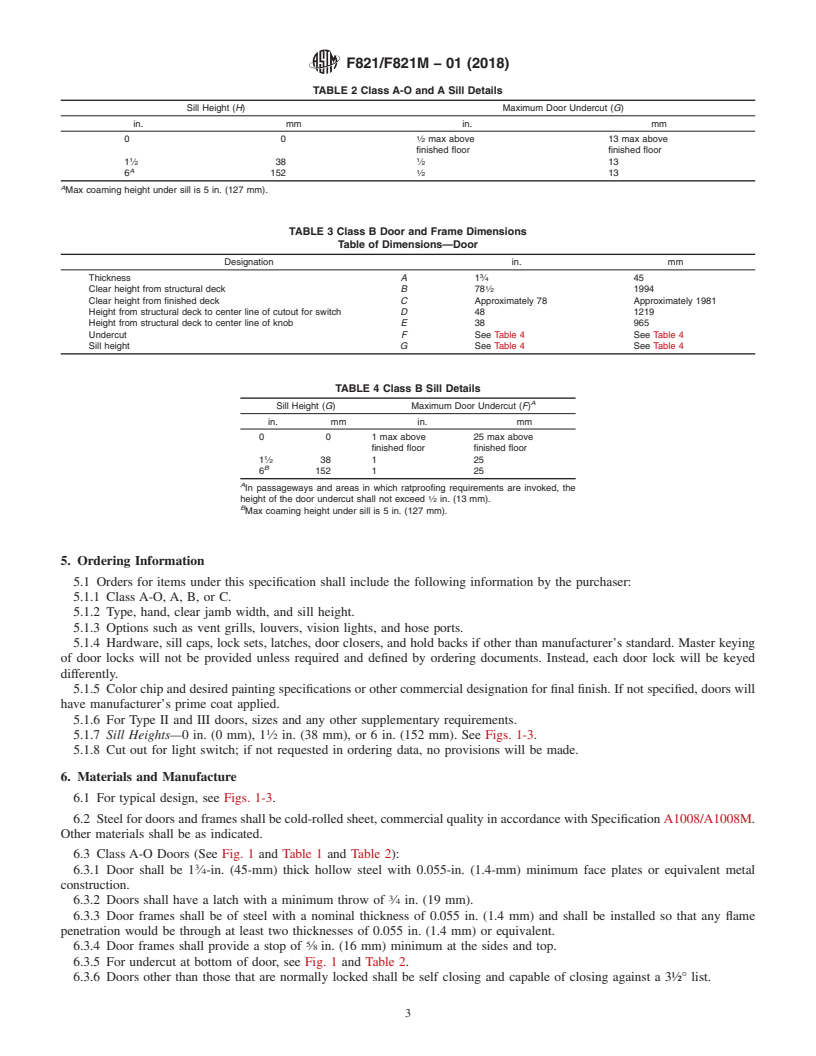
TABLE 2 Class A-O and A Sill Details
Sill Height (H) Maximum Door Undercut (G)
in. mm in. mm
0 0 ⁄2 max above 13 max above
finished floor finished floor
1 1
1 ⁄2 38 ⁄2 13
A
6 152 ⁄2 13
A
Max coaming height under sill is 5 in. (127 mm).
TABLE 3 Class B Door and Frame Dimensions
Table of Dimensions—Door
Designation in. mm
Thickness A 1 ⁄4 45
Clear height from structural deck B 78 ⁄2 1994
Clear height from finished deck C Approximately 78 Approximately 1981
Height from structural deck to center line of cutout for switch D 48 1219
Height from structural deck to center line of knob E 38 965
Undercut F See Table 4 See Table 4
Sill height G See Table 4 See Table 4
TABLE 4 Class B Sill Details
A
Sill Height (G) Maximum Door Undercut (F)
in. mm in. mm
0 0 1 max above 25 max above
finished floor finished floor
1 ⁄2 38 1 25
B
6 152 1 25
A
In passageways and areas in which ratproofing requirements are invoked, the
height of the door undercut shall not exceed ⁄2 in. (13 mm).
B
Max coaming height under sill is 5 in. (127 mm).
5. Ordering Information
5.1 Orders for items under this specification shall include the following information by the purchaser:
5.1.1 Class A-O, A, B, or C.
5.1.2 Type, hand, clear jamb width, and sill height.
5.1.3 Options such as vent grills, louvers, vision lights, and hose ports.
5.1.4 Hardware, sill caps, lock sets, latches, door closers, and hold backs if other than manufacturer’s standard. Master keying
of door locks will not be provided unless required and defined by ordering documents. Instead, each door lock will be keyed
differently.
5.1.5 Color chip and desired painting specifications or other commercial designation for final finish. If not specified, doors will
have manufacturer’s prime coat applied.
5.1.6 For Type II and III doors, sizes and any other supplementary requirements.
5.1.7 Sill Heights—0 in. (0 mm), 1 ⁄2 in. (38 mm), or 6 in. (152 mm). See Figs. 1-3.
5.1.8 Cut out for light switch; if not requested in ordering data, no provisions will be made.
6. Materials and Manufacture
6.1 For typical design, see Figs. 1-3.
6.2 Steel for doors and frames shall be cold-rolled sheet, commercial quality in accordance with Specification A1008/A1008M.
Other materials shall be as indicated.
6.3 Class A-O Doors (See Fig. 1 and Table 1 and Table 2):
6.3.1 Door shall be 1 ⁄4-in. (45-mm) thick hollow steel with 0.055-in. (1.4-mm) minimum face plates or equivalent metal
construction.
6.3.2 Doors shall have a latch with a minimum throw of ⁄4 in. (19 mm).
6.3.3 Door frames shall be of steel with a nominal thickness of 0.055 in. (1.4 mm) and shall be installed so that any flame
penetration would be through at least two thicknesses of 0.055 in. (1.4 mm) or equivalent.
6.3.4 Door frames shall provide a stop of ⁄8 in. (16 mm) minimum at the sides and top.
6.3.5 For undercut at bottom of door, see Fig. 1 and Table 2.
6.3.6 Doors other than those that are normally locked shall be self closing and capable of closing against a 3½° list.
F821/F821M − 01 (2018)
TABLE 5 Class C Door Dimensions
Designation in. mm
Thickness A 1 ⁄4 45
1 Clear height from structural deck B 78 ⁄2 1994
Clear height from finished deck C Approximately 78 Approximately 1981
Height from structural deck to center line of cutout for switch D 48 1219
Height from structural deck to center line of padlock eye E 46 1168
Height from structural deck to center line of knob F 38 965
Undercut G See Table 6 See Table 6
Sill height H See Table 6 See Table 6
TABLE 6 Class C Sill Details
A
Sill Height (H) Maximum Door Undercut (G)
in. mm in. mm
0 0 1 max above 25 max above
finished floor finished floor
1 ⁄2 38 1 25
B
6 152 1 25
A
In passageways and areas in which ratproofing requirements are invoked, the
height of the door undercut shall not exceed ⁄2 in. (13 mm).
B
Max coaming height under sill is 5 in. (127 mm).
NOTE 1—For Class A-O and Class A door requirements, see 6.3 and 6.4, respectively.
FIG. 1 Class A-O and Class A Door and Frame
6.3.7 Doors shall be insulated with sufficient noncombustible fibrous insulation to sound dampen the door adequately. This
insulation shall be selected from those listed under Section 164.007, Structural Insulations, or Section 164.009, Noncombustible
Materials.
6.3.8 Options for Class A-O and A Doors:
2 2
6.3.8.1 Vision lights may be installed using wire-inserted glass of not more than 100 in. (645 cm ) in size.
6.3.8.2 An escape panel of 16- by 18-in. (406- by 457-mm) minimum size in lower half of door.
6.3.8.3 Where hose ports are required, they shall be cut in the lower corner of the door on the side opposite the hinges so that
when hose is passed through the door when the door is open, it may be closed over the hose. The cut for the host port should be
approximately 8 by 8 in. (200 by 200 mm). A hinged or pivoted steel metal cover shall be fitted in the cut, equipped with a method
of holding it in a closed position yet will permit easy and automatic operation of the hinged cover. See Fig. 1 for location.
6.4 Class A Doors (see Fig. 1 and Table 1 and Table 2):
6.4.1 Doors and frames shall follow the requirements of 6.3.1 – 6.3.6 and 6.3.8.
6.4.2 Doors shall be filled solidly with one half the thickness of structural insulation with USCG Approval Number 164.007.
Insulation with USCG Approval Number 164.107 (A-15 rating) may also be used.
6.5 Class B doors (see Fig. 2 and Table 3 and Table 4):
F821/F821M − 01 (2018)
NOTE 1—For Class B door requirements, see 6.5.
FIG. 2 Class “B” Door and Frame
NOTE 1—For Class C door requirements, see 6.6.
FIG. 3 Class C Door and Frame
6.5.1 Doors shall be 1 ⁄4-in. (45-mm) thick hollow steel and constructed of a minimum of 0.044-in. (1.1-mm) face plates.
6.5.2 Doors shall have a latch with a minimum throw of ⁄2 in. (13 mm).
6.5.3 Door frames shall be steel with a minimum 0.055-in. (1.4-mm) thickness if they are an open channel design and a
minimum 0.044 in. (1.1 mm) if they are a tubular design.
6.5.4 Door frames shall provide a stop of ⁄8 in. (16 mm) minimum at the sides and top.
6.5.5 For undercut at bottom of door, see Fig. 2 and Table 4.
6.5.6 Doors shall be insulated with sufficient noncombustible insulation to sound damp the door adequately. This insulation shall
be selected from one of the following USCG approval categories: 164.007, 164.009, 164.107, or 164.109.
6.5.7 Options for Class B Doors:
6.5.7.1 Doors may be fitted with any amount of wire inserted glass, as door construction permits.
6.5.7.2 The lower half of such doors may have a louver. The total net area of louver plus any door undercut shall not exceed
2 2
78 in. (0.05 m ).
6.5.7.3 An escape panel of 16- by 18-in. (406- by 457-mm) minimum size.
6.6 Class C Doors (see Fig. 3 and Table 5 and Table 6):
F821/F821M − 01 (2018)
6.6.1 Doors shall be 1 ⁄4-in. (45-mm) thick hollow steel and constructed of 0.044-in. (1.1-mm) face plates. Aluminum
construction is acceptable and other noncombustible materials will also be considered.
6.6.2 Do
...
Questions, Comments and Discussion
Ask us and Technical Secretary will try to provide an answer. You can facilitate discussion about the standard in here.