


ASTM D785-08(2015)
(Test Method)Standard Test Method for Rockwell Hardness of Plastics and Electrical Insulating Materials
Standard Test Method for Rockwell Hardness of Plastics and Electrical Insulating Materials
SIGNIFICANCE AND USE
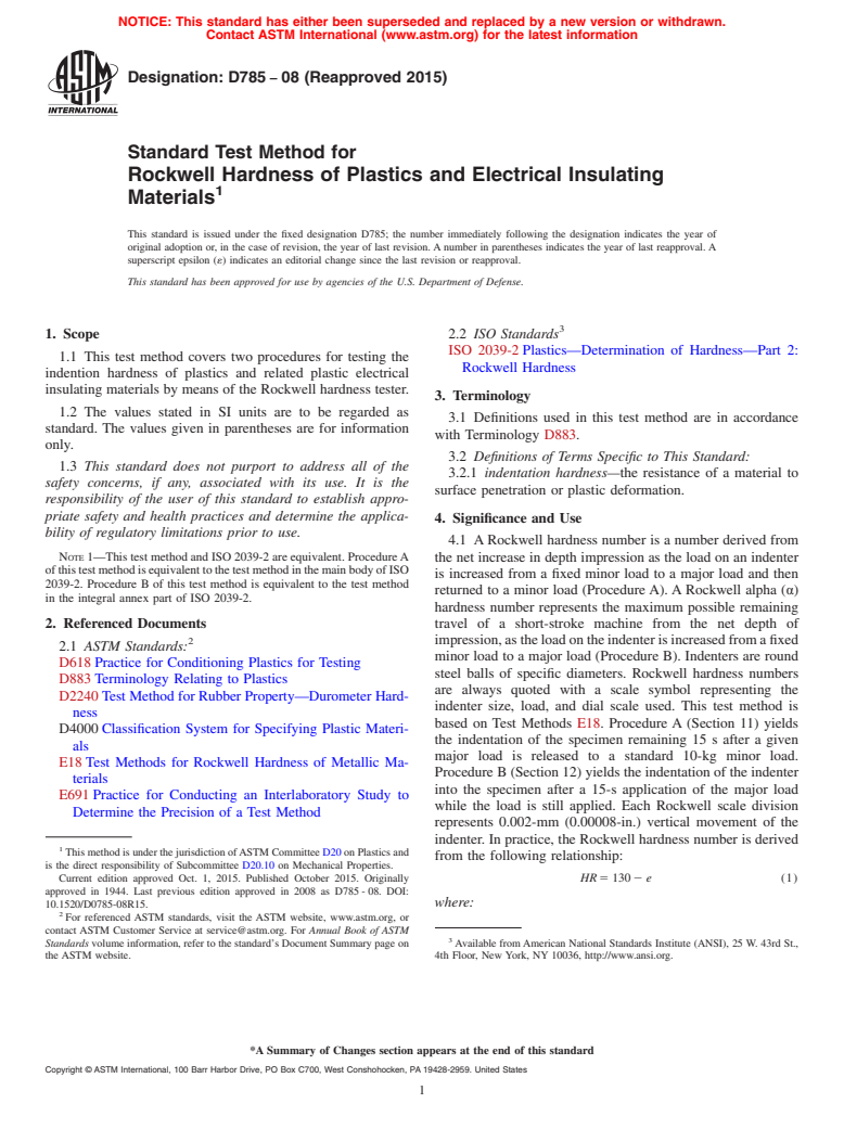
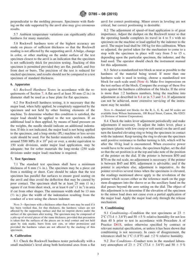
4.1 A Rockwell hardness number is a number derived from the net increase in depth impression as the load on an indenter is increased from a fixed minor load to a major load and then returned to a minor load (Procedure A). A Rockwell alpha (α) hardness number represents the maximum possible remaining travel of a short-stroke machine from the net depth of impression, as the load on the indenter is increased from a fixed minor load to a major load (Procedure B). Indenters are round steel balls of specific diameters. Rockwell hardness numbers are always quoted with a scale symbol representing the indenter size, load, and dial scale used. This test method is based on Test Methods E18. Procedure A (Section 11) yields the indentation of the specimen remaining 15 s after a given major load is released to a standard 10-kg minor load. Procedure B (Section 12) yields the indentation of the indenter into the specimen after a 15-s application of the major load while the load is still applied. Each Rockwell scale division represents 0.002-mm (0.00008-in.) vertical movement of the indenter. In practice, the Rockwell hardness number is derived from the following relationship:
where:
HR = the Rockwell hardness number, and e = the depth of impression after removal of the major load, in units of 0.002 mm. This relation only holds for the E, M, L, R, and K scales.
4.2 A Rockwell hardness number is directly related to the indentation hardness of a plastic material, with the higher the reading the harder the material. An α hardness number is equal to 150 minus the instrument reading. Due to a short overlap of Rockwell hardness scales by Procedure A, two different dial readings on different scales may be obtained on the same material, both of which may be technically correct.
4.3 For certain types of materials having creep and recovery, the time factors involved in applications of major and minor loads have a considerable effect on the results of the measureme...
SCOPE
1.1 This test method covers two procedures for testing the indention hardness of plastics and related plastic electrical insulating materials by means of the Rockwell hardness tester.
1.2 The values stated in SI units are to be regarded as standard. The values given in parentheses are for information only.
1.3 This standard does not purport to address all of the safety concerns, if any, associated with its use. It is the responsibility of the user of this standard to establish appropriate safety and health practices and determine the applicability of regulatory limitations prior to use.
Note 1: This test method and ISO 2039-2 are equivalent. Procedure A of this test method is equivalent to the test method in the main body of ISO 2039-2. Procedure B of this test method is equivalent to the test method in the integral annex part of ISO 2039-2.
General Information
Buy Standard
Standards Content (Sample)
NOTICE: This standard has either been superseded and replaced by a new version or withdrawn.
Contact ASTM International (www.astm.org) for the latest information
Designation: D785 − 08 (Reapproved 2015)
Standard Test Method for
Rockwell Hardness of Plastics and Electrical Insulating
Materials
This standard is issued under the fixed designation D785; the number immediately following the designation indicates the year of
original adoption or, in the case of revision, the year of last revision. A number in parentheses indicates the year of last reapproval. A
superscript epsilon (´) indicates an editorial change since the last revision or reapproval.
This standard has been approved for use by agencies of the U.S. Department of Defense.
1. Scope 2.2 ISO Standards
ISO 2039-2 Plastics—Determination of Hardness—Part 2:
1.1 This test method covers two procedures for testing the
Rockwell Hardness
indention hardness of plastics and related plastic electrical
insulating materials by means of the Rockwell hardness tester.
3. Terminology
1.2 The values stated in SI units are to be regarded as
3.1 Definitions used in this test method are in accordance
standard. The values given in parentheses are for information
with Terminology D883.
only.
3.2 Definitions of Terms Specific to This Standard:
1.3 This standard does not purport to address all of the
3.2.1 indentation hardness—the resistance of a material to
safety concerns, if any, associated with its use. It is the
surface penetration or plastic deformation.
responsibility of the user of this standard to establish appro-
priate safety and health practices and determine the applica-
4. Significance and Use
bility of regulatory limitations prior to use.
4.1 A Rockwell hardness number is a number derived from
NOTE 1—This test method and ISO 2039-2 are equivalent. Procedure A
the net increase in depth impression as the load on an indenter
of this test method is equivalent to the test method in the main body of ISO
is increased from a fixed minor load to a major load and then
2039-2. Procedure B of this test method is equivalent to the test method
returned to a minor load (Procedure A). A Rockwell alpha (α)
in the integral annex part of ISO 2039-2.
hardness number represents the maximum possible remaining
2. Referenced Documents travel of a short-stroke machine from the net depth of
2 impression, as the load on the indenter is increased from a fixed
2.1 ASTM Standards:
minor load to a major load (Procedure B). Indenters are round
D618 Practice for Conditioning Plastics for Testing
steel balls of specific diameters. Rockwell hardness numbers
D883 Terminology Relating to Plastics
are always quoted with a scale symbol representing the
D2240 Test Method for Rubber Property—Durometer Hard-
indenter size, load, and dial scale used. This test method is
ness
based on Test Methods E18. Procedure A (Section 11) yields
D4000 Classification System for Specifying Plastic Materi-
the indentation of the specimen remaining 15 s after a given
als
major load is released to a standard 10-kg minor load.
E18 Test Methods for Rockwell Hardness of Metallic Ma-
Procedure B (Section 12) yields the indentation of the indenter
terials
into the specimen after a 15-s application of the major load
E691 Practice for Conducting an Interlaboratory Study to
while the load is still applied. Each Rockwell scale division
Determine the Precision of a Test Method
represents 0.002-mm (0.00008-in.) vertical movement of the
indenter. In practice, the Rockwell hardness number is derived
This method is under the jurisdiction of ASTM Committee D20 on Plastics and
from the following relationship:
is the direct responsibility of Subcommittee D20.10 on Mechanical Properties.
Current edition approved Oct. 1, 2015. Published October 2015. Originally
HR5 1302 e (1)
approved in 1944. Last previous edition approved in 2008 as D785 - 08. DOI:
10.1520/D0785-08R15. where:
For referenced ASTM standards, visit the ASTM website, www.astm.org, or
contact ASTM Customer Service at service@astm.org. For Annual Book of ASTM
Standards volume information, refer to the standard’s Document Summary page on Available from American National Standards Institute (ANSI), 25 W. 43rd St.,
the ASTM website. 4th Floor, New York, NY 10036, http://www.ansi.org.
*A Summary of Changes section appears at the end of this standard
Copyright © ASTM International, 100 Barr Harbor Drive, PO Box C700, West Conshohocken, PA 19428-2959. United States
D785 − 08 (2015)
Young’s modulus in compression over 3400 MPa (5 × 10 psi).
HR = the Rockwell hardness number, and
Softer plastics and coarse-filled materials will have a wider
e = the depth of impression after removal of the major
range of variation. A large ball indenter will distribute the load
load, in units of 0.002 mm. This relation only holds for
the E, M, L, R, and K scales. more evenly and decrease the range of test results (Note 2). The
sensitivity of the instrument decreases with an increase in the
4.2 A Rockwell hardness number is directly related to the
dial reading and becomes very poor for readings of 100 and
indentation hardness of a plastic material, with the higher the
over due to the shallow indentation of the steel ball. It is
reading the harder the material. An α hardness number is equal
desirable to use the smallest ball and highest load that is
to 150 minus the instrument reading. Due to a short overlap of
practical because of this loss of sensitivity. Rockwell hardness
Rockwell hardness scales by Procedure A, two different dial
readings over 115 are not satisfactory and shall not be reported.
readings on different scales may be obtained on the same
Readings between zero and 100 are recommended, but read-
material, both of which may be technically correct.
ings to 115 are permissible. For comparison purposes, it may
4.3 For certain types of materials having creep and recovery,
be desirable to take readings higher than 115 or lower than zero
the time factors involved in applications of major and minor
on any single scale. In such cases, Rockwell hardness readings
loads have a considerable effect on the results of the measure-
may be reported, but the corresponding correct readings shall
ments.
follow in parentheses, if possible. Such alternate readings are
4.4 The results obtained by this test method are not gener- not always feasible when the specimen is subjected to con-
ally considered a measure of the abrasion or wear resistance of stantly changing conditions or irreversible reactions.
the plastic materials in question.
NOTE 2—Molded specimens containing coarse fiber fillers, such as
4.5 Indentation hardness is used as an indication of cure of
woven glass fabric, will influence the penetration obtained. These varia-
tions in hardness may be reduced by testing with the largest ball indenter
some thermosetting materials at room temperature. Generally,
consistent with the overall hardness of the material.
an uncured specimen has a hardness reading below normal.
5.2 If the bench or table on which a Rockwell hardness
4.6 Each Rockwell hardness scale in Table 1 is an extension
tester is mounted is subject to vibration, such as is experienced
of the proceeding less severe scale, and while there is some
in the vicinity of other machines, the tester should be mounted
overlap between adjacent scales, a correlation table is not
on a metal plate with sponge rubber at least 25 mm (1 in.)
desirable. Readings on one material may be satisfactory for
thick, or on any other type of mounting that will effectually
such a table, but there is no guarantee that other plastic
eliminate vibration from the machine. Otherwise the indenter
materials will give corresponding readings because of differ-
will indent further into the material than when such vibrations
ences in elasticity, creep, and shear characteristics.
are absent.
4.7 Before proceeding with this test method, reference
should be made to the specification of the material being tested.
5.3 Dust, dirt, grease, and scale or rust should not be
Any test specimen preparation, conditioning, dimensions, allowed to accumulate on the indenter, as this will affect the
and/or testing parameters covered in the materials specification
results. Steel ball indenters that have nicks, burrs, or are out of
shall take precedence over those mentioned in this test method.
round shall not be used.
If there are no material specifications, then the default condi-
5.4 The condition of the test equipment is an important
tions apply.
factor in the accuracy of the test results. Dust, dirt or heavy oil
act as a cushion to the load supporting members of the test
5. Factors Affecting Reproducibility and Accuracy
equipment and cause erroneous readings of the instrument dial.
5.1 Rockwell hardness readings have been found reproduc-
The shoulders of the instrument housing, indenter chuck, ball
ible to 62 divisions for certain homogeneous materials with a
seat in the instrument housing, capstan, capstan screw, and
anvil shoulder seat should be kept clean and true. The capstan
and screw should be lightly oiled. Pitted anvil surfaces may be
TABLE 1 Rockwell Hardness Scales
refinished with 600 grit paper.
Rockwell Indenter Diameter
Hardness Minor Major
5.5 Surface conditions of the specimen have a marked effect
Scale Load, Load,
A
(Red Dial kg kg on the readings obtained in a test. Generally, a molded finish
in. mm
Numbers)
will give a higher Rockwell reading than a machined face due
R 10 60 0.5000 ± 12.700 ±
to the high resin content or filled materials or better orientation
0.0001 0.0025
L 10 60 0.2500 ± 6.350 ± and lower plasticizer content of unfilled plastic materials.
0.0001 0.0025
Injection mold specimens in such a way that sink marks and
M 10 100 0.2500 ± 6.350 ±
warpage are minimized. Tubular or unsupported curved speci-
0.0001 0.0025
E 10 100 0.1250 ± 3.175 ± mens are not recommended for plastic hardness testing. Such
0.0001 0.0025
curved surfaces have a tendency to yield with the load and
K 10 150 0.1250 ± 3.175 ±
produce an unsymmetrical indentation pattern.
0.0001 0.0025
A
This major load is not the sum of the actual weights at the back of the frame but
5.6 Many plastic materials have anisotropic characteristics
is a ratio of this load, depending on the leverage arm of machine. One make and
which cause indentation hardness to vary with the direction of
model has a 25 to 1 leverage arm.
testing. In such cases, the hardest face is generally that one
D785 − 08 (2015)
perpendicular to the molding pressure. Specimens with flash- anvil for correct positioning. Minor errors in leveling are not
ing on the side supported by the anvil also may give erroneous critical, but correct positioning is desirable.
results.
8.2 The adjustment of speed-of-load application is of great
5.7 Ambient temperature variations can significantly affect importance. Adjust the dashpot on the Rockwell tester so that
the operating handle completes its travel in 4 to 5 s with no
hardness for many materials.
specimen on the machine or load applied by the indenter to the
5.8 Rockwell hardness tests of the highest accuracy are
anvil. The major load shall be 100 kg for this calibration. When
made on pieces of sufficient thickness so that the Rockwell
so adjusted, the period taken for the mechanism to come to a
reading is not affected by the supporting anvil. A bulge, change
stop with the specimen in place will vary from 5 to 15 s,
in color, or other marking on the under surface of the test
depending upon the particular specimen, the indenter, and the
specimen closest to the anvil is an indication that the specimen
load used. The operator should check the instrument manual
is not sufficiently thick for precision testing. Stacking of thin
for this adjustment.
specimen is permitted provided they are flat, parallel, and free
8.3 Select a standardized test block as near as possible to the
from dust or burrs. The precision of the test is reduced for
hardness of the material being tested. If more than one
stacked specimens, and results should not be compared to a test
hardness scale is used in testing, choose a standardized test
specimen of standard thickness.
block for each scale used (Note 4). Make five impressions on
6. Apparatus
the test surface of the block. Compare the average of these five
tests against the hardness calibration of the blocks. If the error
6.1 Rockwell Hardness Tester, in accordance with the re-
is more than 62 hardness numbers, bring the machine into
quirements of Section 7. A flat anvil at least 50 mm (2 in.) in
adjustment as described in 8.4 or in 5.3 and 5.4. If adjustment
diameter shall be used as a base plate for flat specimens.
can not be achieved, more extensive servicing of the instru-
6.2 For Rockwell hardness testing, it is necessary that the
ment may be needed.
major load, when fully applied, be completely supported by the
NOTE 4—Standard test blocks for the R, L, E, K, and M scales are
specimen and not held by other limiting elements of the
available from Wilson Instruments, 100 Royal Street, Canton, Ma 02021
machine. To determine whether this condition is satisfied, the
(A Division of Instron Corporation).
major load should be applied to the test specimen. If an
8.4 Check the index lever adjustment periodically and make
additional load is then applied, by means of hand pressure on
adjustments if necessary. To adjust the index lever, place a
the weights, the needle should indicate an additional indenta-
specimen (plastic with low creep or soft metal) on the anvil and
tion. If this is not indicated, the major load is not being applied
turn the knurled elevating ring to bring the specimen in contact
to the specimen, and a long-stroke (PL) machine or less severe
with the indenter. Keep turning the ring to elevate the specimen
scale should be used. For the harder materials with a modulus
until positive resistance to further turning is felt, which will be
around 5500 MPa (8 × 10 psi) or over, a stroke equivalent to
after the 10-kg load is encountered. When excessive power
150 scale divisions, under major load application, may be
would have to be used to raise, the specimen higher, set the dial
adequate; but for softer materials the long-stroke (250 scale
so that the set position is at the top and take note of the position
divisions under major load) machine is required.
of the pointer on the dial. If the pointer is between B50 and
7. Test Specimen
B70 on the red scale, no adjustment is necessary; if the pointer
is between B45 and B50, adjustment is advisable; and if the
7.1 The standard test specimen shall have a minimum
1 pointer is anywhere else, adjustment is imperative. As the
thickness of 6 mm ( ⁄4 in.). The specimen may be a piece cut
pointer revolves several times when the specimens is elevated,
from a molding or sheet. Care should be taken that the test
the readi
...
This document is not an ASTM standard and is intended only to provide the user of an ASTM standard an indication of what changes have been made to the previous version. Because
it may not be technically possible to adequately depict all changes accurately, ASTM recommends that users consult prior editions as appropriate. In all cases only the current version
of the standard as published by ASTM is to be considered the official document.
Designation: D785 − 08 D785 − 08 (Reapproved 2015)
Standard Test Method for
Rockwell Hardness of Plastics and Electrical Insulating
Materials
This standard is issued under the fixed designation D785; the number immediately following the designation indicates the year of
original adoption or, in the case of revision, the year of last revision. A number in parentheses indicates the year of last reapproval. A
superscript epsilon (´) indicates an editorial change since the last revision or reapproval.
This standard has been approved for use by agencies of the U.S. Department of Defense.
1. Scope*Scope
1.1 This test method covers two procedures for testing the indention hardness of plastics and related plastic electrical insulating
materials by means of the Rockwell hardness tester.
1.2 The values stated in SI units are to be regarded as standard. The values given in bracketsparentheses are for information
only.
1.3 This standard does not purport to address all of the safety concerns, if any, associated with its use. It is the responsibility
of the user of this standard to establish appropriate safety and health practices and determine the applicability of regulatory
limitations prior to use.
NOTE 1—This test method and ISO 2039-2 are equivalent. Procedure A of this test method is equivalent to the test method in the main body of ISO
2039-2. Procedure B of this test method is equivalent to the test method in the integral annex part of ISO 2039-2.
2. Referenced Documents
2.1 ASTM Standards:
D618 Practice for Conditioning Plastics for Testing
D883 Terminology Relating to Plastics
D2240 Test Method for Rubber Property—Durometer Hardness
D4000 Classification System for Specifying Plastic Materials
E18 Test Methods for Rockwell Hardness of Metallic Materials
E691 Practice for Conducting an Interlaboratory Study to Determine the Precision of a Test Method
2.2 ISO Standards
ISO 2039-2 Plastics—Determination of Hardness—Part 2: Rockwell Hardness
3. Terminology
3.1 Definitions used in this test method are in accordance with Terminology D883.
3.2 Definitions of Terms Specific to This Standard:
3.2.1 indentation hardness—the resistance of a material to surface penetration or plastic deformation.
4. Significance and Use
4.1 A Rockwell hardness number is a number derived from the net increase in depth impression as the load on an indenter is
increased from a fixed minor load to a major load and then returned to a minor load (Procedure A). A Rockwell alpha (α) hardness
number represents the maximum possible remaining travel of a short-stroke machine from the net depth of impression, as the load
on the indenter is increased from a fixed minor load to a major load (Procedure B). Indenters are round steel balls of specific
diameters. Rockwell hardness numbers are always quoted with a scale symbol representing the indenter size, load, and dial scale
used. This test method is based on Test Methods E18. Procedure A (Section 11) yields the indentation of the specimen remaining
This method is under the jurisdiction of ASTM Committee D20 on Plastics and is the direct responsibility of Subcommittee D20.10 on Mechanical Properties.
Current edition approved March 1, 2008Oct. 1, 2015. Published March 2008October 2015. Originally approved in 1944. Last previous edition approved in 20032008 as
D785 - 03.D785 - 08. DOI: 10.1520/D0785-08.10.1520/D0785-08R15.
For referenced ASTM standards, visit the ASTM website, www.astm.org, or contact ASTM Customer Service at service@astm.org. For Annual Book of ASTM Standards
volume information, refer to the standard’s Document Summary page on the ASTM website.
Available from American National Standards Institute (ANSI), 25 W. 43rd St., 4th Floor, New York, NY 10036, http://www.ansi.org.
*A Summary of Changes section appears at the end of this standard
Copyright © ASTM International, 100 Barr Harbor Drive, PO Box C700, West Conshohocken, PA 19428-2959. United States
D785 − 08 (2015)
15 s after a given major load is released to a standard 10-kg minor load. Procedure B (Section 12) yields the indentation of the
indenter into the specimen after a 15-s application of the major load while the load is still applied. Each Rockwell scale division
represents 0.002-mm [0.00008-in.](0.00008-in.) vertical movement of the indenter. In practice, the Rockwell hardness number is
derived from the following relationship:
HR 5 130 2 e (1)
where:
HR = the Rockwell hardness number, and
e = the depth of impression after removal of the major load, in units of 0.002 mm. This relation only holds for the E, M, L,
R, and K scales.
4.2 A Rockwell hardness number is directly related to the indentation hardness of a plastic material, with the higher the reading
the harder the material. An α hardness number is equal to 150 minus the instrument reading. Due to a short overlap of Rockwell
hardness scales by Procedure A, two different dial readings on different scales may be obtained on the same material, both of which
may be technically correct.
4.3 For certain types of materials having creep and recovery, the time factors involved in applications of major and minor loads
have a considerable effect on the results of the measurements.
4.4 The results obtained by this test method are not generally considered a measure of the abrasion or wear resistance of the
plastic materials in question.
4.5 Indentation hardness is used as an indication of cure of some thermosetting materials at room temperature. Generally, an
uncured specimen has a hardness reading below normal.
4.6 Each Rockwell hardness scale in Table 1 is an extension of the proceeding less severe scale, and while there is some overlap
between adjacent scales, a correlation table is not desirable. Readings on one material may be satisfactory for such a table, but there
is no guarantee that other plastic materials will give corresponding readings because of differences in elasticity, creep, and shear
characteristics.
4.7 Before proceeding with this test method, reference should be made to the specification of the material being tested. Any test
specimen preparation, conditioning, dimensions, and/or testing parameters covered in the materials specification shall take
precedence over those mentioned in this test method. If there are no material specifications, then the default conditions apply.
5. Factors Affecting Reproducibility and Accuracy
5.1 Rockwell hardness readings have been found reproducible to 62 divisions for certain homogeneous materials with a
Young’s modulus in compression over 3400 MPa [5(5 × 10 psi].psi). Softer plastics and coarse-filled materials will have a wider
range of variation. A large ball indenter will distribute the load more evenly and decrease the range of test results (Note 2). The
sensitivity of the instrument decreases with an increase in the dial reading and becomes very poor for readings of 100 and over
due to the shallow indentation of the steel ball. It is desirable to use the smallest ball and highest load that is practical because of
this loss of sensitivity. Rockwell hardness readings over 115 are not satisfactory and shall not be reported. Readings between zero
and 100 are recommended, but readings to 115 are permissible. For comparison purposes, it may be desirable to take readings
higher than 115 or lower than zero on any single scale. In such cases, Rockwell hardness readings may be reported, but the
corresponding correct readings shall follow in parentheses, if possible. Such alternate readings are not always feasible when the
specimen is subjected to constantly changing conditions or irreversible reactions.
TABLE 1 Rockwell Hardness Scales
Rockwell Indenter Diameter
Hardness Minor Major
Scale Load, Load,
A
(Red Dial kg kg
in. mm
Numbers)
R 10 60 0.5000 ± 12.700 ±
0.0001 0.0025
L 10 60 0.2500 ± 6.350 ±
0.0001 0.0025
M 10 100 0.2500 ± 6.350 ±
0.0001 0.0025
E 10 100 0.1250 ± 3.175 ±
0.0001 0.0025
K 10 150 0.1250 ± 3.175 ±
0.0001 0.0025
A
This major load is not the sum of the actual weights at the back of the frame but
is a ratio of this load, depending on the leverage arm of machine. One make and
model has a 25 to 1 leverage arm.
D785 − 08 (2015)
NOTE 2—Molded specimens containing coarse fiber fillers, such as woven glass fabric, will influence the penetration obtained. These variations in
hardness may be reduced by testing with the largest ball indenter consistent with the overall hardness of the material.
5.2 If the bench or table on which a Rockwell hardness tester is mounted is subject to vibration, such as is experienced in the
vicinity of other machines, the tester should be mounted on a metal plate with sponge rubber at least 25 mm [1 in.](1 in.) thick,
or on any other type of mounting that will effectually eliminate vibration from the machine. Otherwise the indenter will indent
further into the material than when such vibrations are absent.
5.3 Dust, dirt, grease, and scale or rust should not be allowed to accumulate on the indenter, as this will affect the results. Steel
ball indenters that have nicks, burrs, or are out of round shall not be used.
5.4 The condition of the test equipment is an important factor in the accuracy of the test results. Dust, dirt or heavy oil act as
a cushion to the load supporting members of the test equipment and cause erroneous readings of the instrument dial. The shoulders
of the instrument housing, indenter chuck, ball seat in the instrument housing, capstan, capstan screw, and anvil shoulder seat
should be kept clean and true. The capstan and screw should be lightly oiled. Pitted anvil surfaces may be refinished with 600 grit
paper.
5.5 Surface conditions of the specimen have a marked effect on the readings obtained in a test. Generally, a molded finish will
give a higher Rockwell reading than a machined face due to the high resin content or filled materials or better orientation and lower
plasticizer content of unfilled plastic materials. Injection mold specimens in such a way that sink marks and warpage are
minimized. Tubular or unsupported curved specimens are not recommended for plastic hardness testing. Such curved surfaces have
a tendency to yield with the load and produce an unsymmetrical indentation pattern.
5.6 Many plastic materials have anisotropic characteristics which cause indentation hardness to vary with the direction of
testing. In such cases, the hardest face is generally that one perpendicular to the molding pressure. Specimens with flashing on the
side supported by the anvil also may give erroneous results.
5.7 Ambient temperature variations can significantly affect hardness for many materials.
5.8 Rockwell hardness tests of the highest accuracy are made on pieces of sufficient thickness so that the Rockwell reading is
not affected by the supporting anvil. A bulge, change in color, or other marking on the under surface of the test specimen closest
to the anvil is an indication that the specimen is not sufficiently thick for precision testing. Stacking of thin specimen is permitted
provided they are flat, parallel, and free from dust or burrs. The precision of the test is reduced for stacked specimens, and results
should not be compared to a test specimen of standard thickness.
6. Apparatus
6.1 Rockwell Hardness Tester, in accordance with the requirements of Section 7. A flat anvil at least 50 mm [2 in.](2 in.) in
diameter shall be used as a base plate for flat specimens.
6.2 For Rockwell hardness testing, it is necessary that the major load, when fully applied, be completely supported by the
specimen and not held by other limiting elements of the machine. To determine whether this condition is satisfied, the major load
should be applied to the test specimen. If an additional load is then applied, by means of hand pressure on the weights, the needle
should indicate an additional indentation. If this is not indicated, the major load is not being applied to the specimen, and a
long-stroke (PL) machine or less severe scale should be used. For the harder materials with a modulus around 5500 MPa [8(8 ×
10 psi]psi) or over, a stroke equivalent to 150 scale divisions, under major load application, may be adequate; but for softer
materials the long-stroke (250 scale divisions under major load) machine is required.
7. Test Specimen
7.1 The standard test specimen shall have a minimum thickness of 6 mm [( ⁄4 in.].in.). The specimen may be a piece cut from
a molding or sheet. Care should be taken that the test specimen has parallel flat surfaces to ensure good seating on the anvil and
thus avoid the deflection that may be caused by poor contact. The specimen shall be at least 25 mm [1 in.](1 in.) square if cut from
2 2
sheet stock, or at least 6 cm [1(1 in. ]) in area if cut from other shapes. The minimum width shall be 13 mm [( ⁄2 in.]in.) plus the
width of the indentation resulting from the conduct of a test using the chosen indenter.
NOTE 3—Specimen with a thickness other than 6 mm may be used if it has been verified that, for that thickness, the hardness values are not affected
by the supporting surface and that no imprint shows under the surface of the specimen after testing. The specimen may be composed of a pile-up of several
pieces of the same thickness, provided that precaution is taken that the surfaces of the pieces are in total contact and not held apart by sink marks, burrs
from saw cuts, or other protrusions and provided the hardness values are not affected by the stacking of thin specimens.
8. Calibration
8.1 Check the Rockwell hardness tester periodically with a small machinist’s level along both horizontal axes from a flat anvil
for correct positioning. Minor errors in leveling are not critical, but correct positioning is desirable.
8.2 The adjustment of speed-of-load application is of great importance. Adjust the dashpot on the Rockwell tester so that the
operating handle completes its travel in 4 to 5 s with no specimen on the machine or load applied by the indenter to the anvil. The
major load shall be 100 kg for this calibration. When so adjusted, the period taken for the mechanism to come to a stop with the
D785 − 08 (2015)
specimen in place will vary from 5 to 15 s, depending upon the particular specimen, the indenter, and the load used. The operator
should check the instrument manual for this adjustment.
8.3 Select a standardized test block as near as possible to the hardness
...
Questions, Comments and Discussion
Ask us and Technical Secretary will try to provide an answer. You can facilitate discussion about the standard in here.