


ASTM F15-04(2017)
(Specification)Standard Specification for Iron-Nickel-Cobalt Sealing Alloy
Standard Specification for Iron-Nickel-Cobalt Sealing Alloy
ABSTRACT
This specification covers an iron-nickel-cobalt alloy for use in sealing to glass in electronic applications. The alloy shall conform to the chemical composition specified and shall be manufactured in the form of wire, rod, bar, strip, sheet, and tube, with each form available in the specified temper condition. For example, tubes shall be bright annealed and supplied in the annealed temper condition. Strip and sheet shall be of temper A, B, C, D, or E or in deep-drawing temper condition, while wire and rod shall be bright annealed and supplied in temper A condition unless specified otherwise. The material shall be smooth, uniform in cross section, composition, and temper, and free of scale, corrosion, cracks, seams, scratches, slivers, and other defects. Tests for hardness, tensile strength, thermal expansion, and transformation shall be performed and shall conform to the requirements specified.
SCOPE
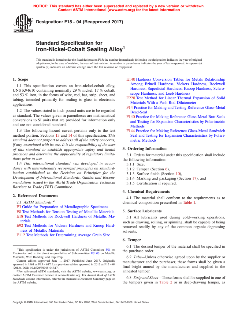
1.1 This specification covers an iron-nickel-cobalt alloy, UNS K94610 containing nominally 29 % nickel, 17 % cobalt, and 53 % iron, in the forms of wire, rod, bar, strip, sheet, and tubing, intended primarily for sealing to glass in electronic applications.
1.2 The values stated in inch-pound units are to be regarded as standard. The values given in parentheses are mathematical conversions to SI units that are provided for information only and are not considered standard.
1.3 The following hazard caveat pertains only to the test method portion, Sections 13 and 14 of this specification. This standard does not purport to address all of the safety concerns, if any, associated with its use. It is the responsibility of the user of this standard to establish appropriate safety and health practices and determine the applicability of regulatory limitations prior to use.
1.4 This international standard was developed in accordance with internationally recognized principles on standardization established in the Decision on Principles for the Development of International Standards, Guides and Recommendations issued by the World Trade Organization Technical Barriers to Trade (TBT) Committee.
General Information
Buy Standard
Standards Content (Sample)
NOTICE: This standard has either been superseded and replaced by a new version or withdrawn.
Contact ASTM International (www.astm.org) for the latest information
Designation:F15 −04 (Reapproved 2017)
Standard Specification for
Iron-Nickel-Cobalt Sealing Alloy
ThisstandardisissuedunderthefixeddesignationF15;thenumberimmediatelyfollowingthedesignationindicatestheyearoforiginal
adoptionor,inthecaseofrevision,theyearoflastrevision.Anumberinparenthesesindicatestheyearoflastreapproval.Asuperscript
epsilon (´) indicates an editorial change since the last revision or reapproval.
1. Scope E140Hardness Conversion Tables for Metals Relationship
Among Brinell Hardness, Vickers Hardness, Rockwell
1.1 This specification covers an iron-nickel-cobalt alloy,
Hardness, Superficial Hardness, Knoop Hardness, Sclero-
UNS K94610 containing nominally 29% nickel, 17% cobalt,
scope Hardness, and Leeb Hardness
and 53% iron, in the forms of wire, rod, bar, strip, sheet, and
E228Test Method for Linear Thermal Expansion of Solid
tubing, intended primarily for sealing to glass in electronic
Materials With a Push-Rod Dilatometer
applications.
F14Practice for Making andTesting Reference Glass-Metal
1.2 Thevaluesstatedininch-poundunitsaretoberegarded
Bead-Seal
as standard. The values given in parentheses are mathematical
F140Practice for Making Reference Glass-Metal Butt Seals
conversions to SI units that are provided for information only
and Testing for Expansion Characteristics by Polarimetric
and are not considered standard.
Methods
1.3 The following hazard caveat pertains only to the test F144Practice for Making Reference Glass-Metal Sandwich
method portion, Sections 13 and 14 of this specification. This
Seal and Testing for Expansion Characteristics by Polari-
standard does not purport to address all of the safety concerns, metric Methods
if any, associated with its use. It is the responsibility of the user
3. Ordering Information
of this standard to establish appropriate safety and health
practices and determine the applicability of regulatory limita-
3.1 Ordersformaterialunderthisspecificationshallinclude
tions prior to use.
the following information:
1.4 This international standard was developed in accor-
3.1.1 Size,
dance with internationally recognized principles on standard-
3.1.2 Temper (Section 6),
ization established in the Decision on Principles for the
3.1.3 Surface finish (Section 10),
Development of International Standards, Guides and Recom-
3.1.4 Marking and packaging (Section 17), and
mendations issued by the World Trade Organization Technical
3.1.5 Certification if required.
Barriers to Trade (TBT) Committee.
4. Chemical Requirements
2. Referenced Documents
4.1 The material shall conform to the requirements as to
2.1 ASTM Standards:
chemical composition prescribed in Table 1.
E3Guide for Preparation of Metallographic Specimens
5. Surface Lubricants
E8Test Methods for Tension Testing of Metallic Materials
E18Test Methods for Rockwell Hardness of Metallic Ma-
5.1 All lubricants used during cold-working operations,
terials
such as drawing, rolling, or spinning, shall be capable of being
E92Test Methods for Vickers Hardness and Knoop Hard-
removed readily by any of the common organic degreasing
ness of Metallic Materials
solvents.
E112Test Methods for Determining Average Grain Size
6. Temper
6.1 The desired temper of the material shall be specified in
This specification is under the jurisdiction of ASTM Committee F01 on
the purchase order.
Electronics and is the direct responsibility of Subcommittee F01.03 on Metallic
Materials, Wire Bonding, and Flip Chip.
6.2 Tube—Unless otherwise agreed upon by the supplier or
Current edition approved June 1, 2017. Published June 2017. Originally
manufacturer and the purchaser, these forms shall be given a
approvedin1961asF15–61T.Lastpreviouseditionapprovedin2013asF15–04
final bright anneal by the manufacturer and supplied in the
(2013). DOI: 10.1520/F0015-04R17.
For referenced ASTM standards, visit the ASTM website, www.astm.org, or annealed temper.
contact ASTM Customer Service at service@astm.org. For Annual Book of ASTM
6.3 Strip and Sheet—Theseformsshallbesuppliedinoneof
Standards volume information, refer to the standard’s Document Summary page on
the ASTM website. the tempers given in Table 2 or in deep-drawing temper, as
Copyright © ASTM International, 100 Barr Harbor Drive, PO Box C700, West Conshohocken, PA 19428-2959. United States
F15−04 (Reapproved 2017)
specified.
F15−04 (2017)
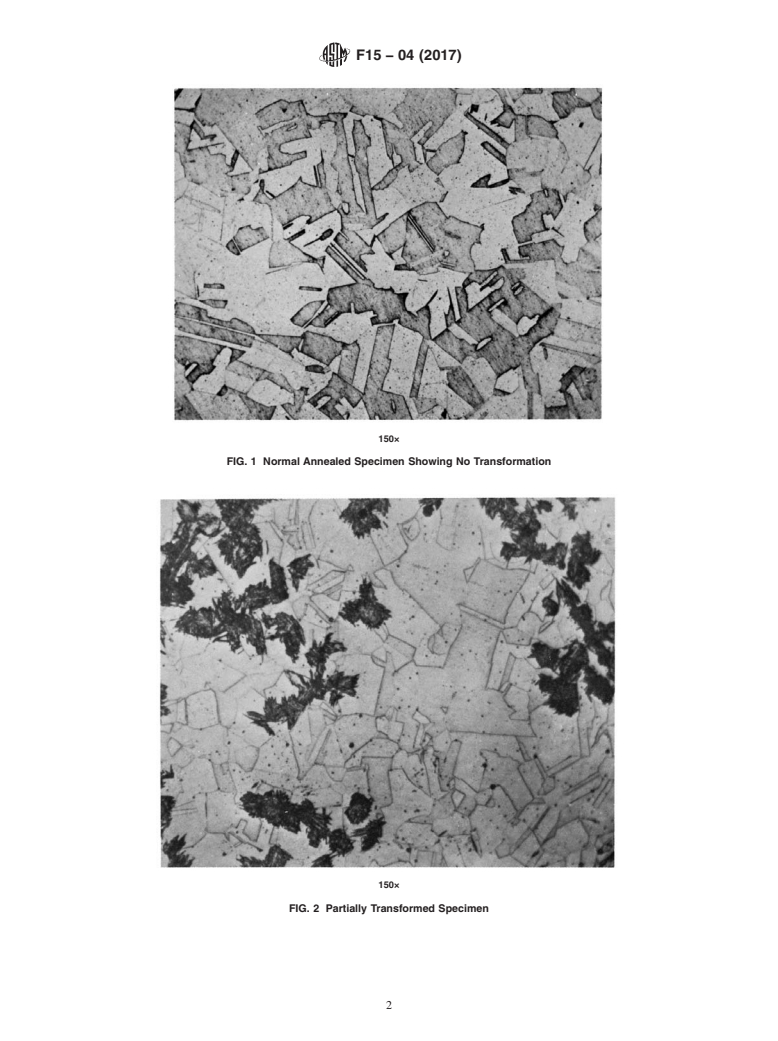
150×
FIG. 1 Normal Annealed Specimen Showing No Transformation
150×
FIG. 2 Partially Transformed Specimen
F15−04 (2017)
TABLE 1 Chemical Requirements
8.2 Rolled and Annealed Tempers—Hardness tests when
Element Composition, % properlyappliedcanbeindicativeoftensilestrength.Hardness
A
Iron, nominal 53 scales and ranges for these tempers, if desirable, shall be
A
Nickel, nominal 29
negotiated between supplier and purchaser.
A
Cobalt, nominal 17
Manganese, max 0.50
9. Tensile Strength
Silicon, max 0.20
Carbon, max 0.04
9.1 Sheet and Strip:
B
Aluminum, max 0.10
B
9.1.1 Tensile strength shall be the basis for acceptance or
Magnesium, max 0.10
B
Zirconium, max 0.10
rejection for the tempers given in Table 2 and shall conform
B
Titanium, max 0.10
with the requirements prescribed.
Copper, max 0.20
9.1.2 Tension test specimens shall be taken so the longitu-
Chromium, max 0.20
Molybdenum, max 0.20
dinalaxisisparalleltothedirectionofrollingandthetestshall
A
The iron, nickel, and cobalt requirements listed are nominal. They shall be be performed in accordance with Test Methods E8.
adjusted by the manufacturer so that the alloy meets the requirements for
9.2 Wire and Rod:
coefficient of thermal expansion given in Table 4.
B
The total of aluminum, magnesium, zirconium, and titanium shall not exceed
9.2.1 Tensile strength shall be the basis for acceptance or
0.20 %.
rejectionforthetempersgiveninTable3.andshallconformto
the requirements prescribed.
9.2.2 The test shall be performed in accordance with Test
TABLE 2 Tensile Strength Requirements for Sheet and Strip
Method E8.
Temper
Temper Name Tensile Strength, ksi(MPa)
Designation
10. Surface Finish
A annealed 82 max (570 max)
B ⁄4 hard 75 to 90 (520 to 630)
10.1 The standard surface finishes available shall be those
C half hard 85 to 100 (590 to 700)
resulting from the following operations:
D ⁄4 hard 95 to 110 (660 to 770)
10.1.1 Hot rolling,
E hard 100 min (700 min)
10.1.2 Forging,
10.1.3 Centerless grinding (rod),
10.1.4 Belt polishing,
10.1.5 Cold rolling, and
6.4 Wire and Rod—These forms shall be supplied in one of
10.1.6 Wire drawing.
the tempers given in Table 3 as specified. Unless otherwise
specified, the material shall be bright annealed and supplied in
11. Thermal Expansion Characteristics
temper A (annealed).
11.1 The average linear coefficients of thermal expansion
shall be within the limits specified in Table 4.
7. Grain Size
7.1 Strip and sheet for deep drawing shall have an average
12. Test for Thermal Expansion
grain size not larger thanASTM No. 5 (Note 1), and no more
12.1 Heat the specimen in a hydrogen atmosphere for1hat
than 10% of the grains shall be larger than No. 5 when
900°C, followed by 15 min at 1100°C. Between the 900 and
measured in accordance with Test Methods E112.
1100°C heat-treatment periods, the specimen may be cooled to
NOTE1—Thiscorrespondstoagrainsizeof0.065mm,or16grains/in.
room temperature if desired. Cool the specimen from 1100 to
of image at 100×.
200°C in the hydrogen atmosphere at a rate not to exceed
5°C/min.
8. Hardness
12.2 Determine the thermal expansion characteristics in
8.1 Deep-Drawing Temper—Fordeepdrawing,thehardness
accordance with Test Method E228.
shall not exceed 82 HRB for material 0.100 in. (2.54 mm) and
NOTE 2—For critical glass sealing applications, it is recommended that
less in thickness and 85 HRB for material over 0.100 in. in
theuserconductfunctionaltestinginaccordancewithPracticesF14,F140
thickness when determined in accordance with Test Methods
or F144. Such tests circumvent possible problems with thermal expansion
E18.SeealsoTestMethodE92forVickersHardnessandTable
measurements and glass setting point estimates.
3, E140 for the appropriate conversion between various hard-
NOTE3—Thethermaltreatmentdescribedinthissectionisforpurposes
ness scales.
of the thermal expansion test only. Consult the non-mandatory appendix
TABLE 4 Coefficients of Thermal Expansion
TABLE 3 Tensile Strength Requirements for Wire and Rod
Average Linear Coefficient
A
Temperature Range, °C of Thermal Expansion,
Temper Designation Tensile Strength, ksi (MPa)
µm/m·°C
A 85 (585) max
30 to 400 4.60 to 5.20
B 85 to 105 (585 to 725)
30 to 450 5.10 to 5.50
C 95 to 115 (655 to 795)
A
D 105 to 125 (725 to 860) Typical thermal expansion data for the alloy covered by these specifications are
E 125 (860) min
provided in Appendix X1.
F15−04 (2017)
ofthisdocumentforguidanceonannealingconditionsforvariousproduct
15. Dimensions and Permissible Variations
forms.
15.1 Cold-Rolled Strip—Cold-rolled strip shall conform to
13. Transformation the permissible variations in dimensions prescribed in Table 5,
Table 6, and Table 7.
13.1 Thetemperatureofthegamma-to-alphatransformation
shall be below−78.5°C when the material is tested in accor- 15.2 Round Wire and Rod—Wire and rod shall conform to
dance with Section 14. However, for material whose smallest the permissible variations in dimensions prescribed in Table 8.
dimension is over ⁄8 in. (22.2 mm), some localized
15.3 Cold-Drawn Tubing—Cold-drawntubing,availableei-
transformation, acceptable to the purchaser, may be tolerated.
ther as seamless or welded, shall conform to the permissible
NOTE 4—Lower transformation temperatures, ranging to as low as
variations prescribed in Table 9.
−196°C, may be negotiated between supplier and purchaser. The −196°C
transformation temperature corresponds to immersing a sample (prepared
16. General Requirements
according to 14.1) in liquid nitrogen for a minimum of 1 h.
16.1 Thematerialshallbecommerciallysmooth,uniformin
14. Test for Transformation
cross section, in composition, and in temper; it shall be free of
14.1 Cut the specimen from any part of the material, but
scale, corrosion, cracks, seams, scratches, slivers, and other
preferably including the entire cross section, degrease it, then
defects as best commercial practice will permit.
heat treat it as described in 12.1. When cool, polish the cross
17. Packaging and Marking
sectionofthespecimenandetch(Note5)itinaccordancewith
Method E3. Then subject the specimen to the temperature
17.1 Packaging shall be subject to agreement between the
produced by an excess of dry ice in acetone (−78.5°C) for at
purchaser and the seller.
least 4 h. After the low-temperature treatment, examine the
17.2 The material as furnished under this specification shall
specimen at a mangification of 150× for the presence of the
beidentifiedbythenameorsymbolofthemanufacturerandby
acicular crystals characteristic of the alpha phase. Because
melt number.The lot size for determining compliance with the
thesecrystalsmayoccuronlyinsmalllocalizedareas,examine
requirements of this specification shall be one heat.
carefully the entire polished cross section.
18. Investigation of Claims
14.2 Specimens that show no transformation and that show
partial transformation are illustrated in Fig. 1 and Fig. 2,
18.1 Where any material fails to meet the requirements of
respectively.
thisspecification,thematerialsodesignatedshallbehandledin
accordance with a mutual agreement between the purchaser
NOTE 5—Asuggested etchant is a solution of three parts by volume of
and the seller.
concentrated hydrochloric acid and one part of concentrated nitric acid
saturated with cupric chloride (CuCl ·2H O). This etchant is more
2 2
19. Keywords
effective when allowed to stand for 20 min after mixing. After several
hours it loses its strength and should be discarded at the end of the day.
19.1 controlled expansion alloy; glass to metal sealing;
Etching is best accomplished by swabbing the specimen with cotton
iron-nickel-cobalt alloy; UNS #K94610; vacuum electronic
soaked with the etchant. Etching is usually complete when the surface of
the metal appears to have turned dull. applications
TABLE 5 Permissible Variations in Thickness of Cold-Rolled Strip
NOTE 1— Measurement shall be made at least ⁄8 in. (9.5 mm) from the edge of strip over 1 in. (25.4 mm) wide.
Permissible Variations in Thickness for Width Given, ± in. (mm)
Specified Thickness, in. (mm)
Under 3 (76) Over 3 to 6 (76 to 152) Over 6 to 12 (152 to 305) Over 12 to 16 (305 to 406)
0.160 to 0.100 (4.06 to 2.54), incl 0.002 (0.051) 0.003 (0.076) 0.004 (0.102) 0.004 (0.102)
0.099 to 0.069 (2.51 to 1.75), incl 0.002 (0.051) 0.003 (0.076) 0.003 (0.076) 0.004 (0.102)
0.068 to 0.050 (1.73 to 1.27), incl 0.002 (0.051) 0.003 (0.076) 0.003 (0.076) 0.003 (0.076)
0.049 to 0.035 (1.24 to 0.89), incl 0.002 (0.051) 0.0025 (0.064) 0.003 (0.076) 0.003 (0.076)
0.034 to 0.029 (0.86 to 0.74), incl 0.0015 (0.038) 0.002 (0.051) 0.0025 (0.064) 0.0025 (0.064)
0.028 to 0.026 (0.71 to 0.66), incl 0.0015 (0.038) 0.0015 (0.038) 0.002 (0.051) 0.002 (0.051)
0.025 to 0.020 (0.64 to 0.51), incl 0.001 (0.025) 0.0015 (0.038) 0.002 (0.051) 0.002 (0.051)
0.019 to 0.017 (0.48 to 0.43), incl 0.001 (0.025) 0.001 (0.025) 0.0015 (0.038) 0.002 (0.051)
0.016 to 0.012 (0.41 to 0.31), incl 0.001 (0.025) 0.001 (0.025) 0.0015 (0.038) 0.0015 (0.038)
0.011 to 0.0101 (0.28 to 0.26), incl 0.001 (0.025) 0.001 (0.025) 0.001 (0.025) 0.0015 (0.038)
0.010 to 0.0091 (0.25 to 0.23), incl 0.001 (0.025) 0.001 (0.025) 0.001 (0.025) 0.001 (0.025)
0.009 to 0.006 (0.23 to 0.15), incl 0.00075 (0.019) 0.00075 (0.019) . .
Under 0.006 (0.15) 0.0005 (0.013) 0.0005 (0.013) . .
F15−04 (2017)
TABLE 6 Permissible Variations in Thickness Across Width of Strip
Maximum Variation in Thickness Across Width of Strip, Within Those Provided for in
Specified Thickness
Table 4 for Edge Measurements for Widths and Thicknesses Given, in. (mm)
Over 12 to 24 (300 to
5 (127) and Under Over 5 to 12 (127 to 300)
in. mm 600), incl
in. mm in. mm in. mm
0.005 to 0.010, incl 0.17 to 0.03, incl 0.00075 0.0191 0.001 0.025 0.0015 0.038
Over 0.010 to 0.025, incl 0.03 to 0.06, incl 0.001 0.025 0.0015 0.038 0.002 0.051
Over 0.025 to 0.065, incl 0.06 to 0.16, incl 0.0015 0.038 0.002 0.051 0.0025 0.064
Over 0.065 to ⁄16 , excl 0.16 to 0.48, excl 0.002 0.051 0.0025 0.064 0.003 0.076
TABLE 7 Permissible Variations in Width of Cold-Rolled Strip Supplied in Coils
Permissible Variations in Width for Widths Given, ± in. (mm)
Specified Thickness, in. (mm) 1 3 1 15
Under ⁄2 to ⁄16 ⁄2to6(12.7to Over 6 to 9 (152 Over 9 to 12 (229 Ov
...
This document is not an ASTM standard and is intended only to provide the user of an ASTM standard an indication of what changes have been made to the previous version. Because
it may not be technically possible to adequately depict all changes accurately, ASTM recommends that users consult prior editions as appropriate. In all cases only the current version
of the standard as published by ASTM is to be considered the official document.
Designation: F15 − 04 (Reapproved 2013) F15 − 04 (Reapproved 2017)
Standard Specification for
Iron-Nickel-Cobalt Sealing Alloy
This standard is issued under the fixed designation F15; the number immediately following the designation indicates the year of original
adoption or, in the case of revision, the year of last revision. A number in parentheses indicates the year of last reapproval. A superscript
epsilon (´) indicates an editorial change since the last revision or reapproval.
1. Scope
1.1 This specification covers an iron-nickel-cobalt alloy, UNS K94610 containing nominally 29 % nickel, 17 % cobalt, and
53 % iron, in the forms of wire, rod, bar, strip, sheet, and tubing, intended primarily for sealing to glass in electronic applications.
1.2 The values stated in inch-pound units are to be regarded as standard. The values given in parentheses are mathematical
conversions to SI units that are provided for information only and are not considered standard.
1.3 The following hazard caveat pertains only to the test method portion, Sections 13 and 14 of this specification.This standard
does not purport to address all of the safety concerns, if any, associated with its use. It is the responsibility of the user of this
standard to establish appropriate safety and health practices and determine the applicability of regulatory limitations prior to use.
1.4 This international standard was developed in accordance with internationally recognized principles on standardization
established in the Decision on Principles for the Development of International Standards, Guides and Recommendations issued
by the World Trade Organization Technical Barriers to Trade (TBT) Committee.
2. Referenced Documents
2.1 ASTM Standards:
E3 Guide for Preparation of Metallographic Specimens
E8 Test Methods for Tension Testing of Metallic Materials
E18 Test Methods for Rockwell Hardness of Metallic Materials
E92 Test Methods for Vickers Hardness and Knoop Hardness of Metallic Materials
E112 Test Methods for Determining Average Grain Size
E140 Hardness Conversion Tables for Metals Relationship Among Brinell Hardness, Vickers Hardness, Rockwell Hardness,
Superficial Hardness, Knoop Hardness, Scleroscope Hardness, and Leeb Hardness
E228 Test Method for Linear Thermal Expansion of Solid Materials With a Push-Rod Dilatometer
F14 Practice for Making and Testing Reference Glass-Metal Bead-Seal
F140 Practice for Making Reference Glass-Metal Butt Seals and Testing for Expansion Characteristics by Polarimetric Methods
F144 Practice for Making Reference Glass-Metal Sandwich Seal and Testing for Expansion Characteristics by Polarimetric
Methods
3. Ordering Information
3.1 Orders for material under this specification shall include the following information:
3.1.1 Size,
3.1.2 Temper (Section 6),
3.1.3 Surface finish (Section 10),
3.1.4 Marking and packaging (Section 17), and
3.1.5 Certification if required.
4. Chemical Requirements
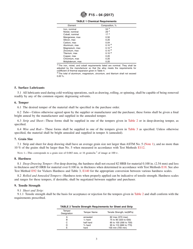
4.1 The material shall conform to the requirements as to chemical composition prescribed in Table 1.
This specification is under the jurisdiction of ASTM Committee F01 on Electronics and is the direct responsibility of Subcommittee F01.03 on Metallic
MaterialsMaterials, Wire Bonding, and Flip Chip.
Current edition approved May 1, 2013June 1, 2017. Published May 2013June 2017. Originally approved in 1961 as F15 – 61T. Last previous edition approved in 20092013
as F15 – 04 (2009).(2013). DOI: 10.1520/F0015-04R13.10.1520/F0015-04R17.
For referenced ASTM standards, visit the ASTM website, www.astm.org, or contact ASTM Customer Service at service@astm.org. For Annual Book of ASTM Standards
volume information, refer to the standard’s Document Summary page on the ASTM website.
Copyright © ASTM International, 100 Barr Harbor Drive, PO Box C700, West Conshohocken, PA 19428-2959. United States
F15 − 04 (2017)
150×
FIG. 1 Normal Annealed Specimen Showing No Transformation
150×
FIG. 2 Partially Transformed Specimen
F15 − 04 (2017)
TABLE 1 Chemical Requirements
Element Composition, %
A
Iron, nominal 53
A
Nickel, nominal 29
A
Cobalt, nominal 17
Manganese, max 0.50
Silicon, max 0.20
Carbon, max 0.04
B
Aluminum, max 0.10
B
Magnesium, max 0.10
B
Zirconium, max 0.10
B
Titanium, max 0.10
Copper, max 0.20
Chromium, max 0.20
Molybdenum, max 0.20
A
The iron, nickel, and cobalt requirements listed are nominal. They shall be
adjusted by the manufacturer so that the alloy meets the requirements for
coefficient of thermal expansion given in Table 4.
B
The total of aluminum, magnesium, zirconium, and titanium shall not exceed
0.20 %.
5. Surface Lubricants
5.1 All lubricants used during cold-working operations, such as drawing, rolling, or spinning, shall be capable of being removed
readily by any of the common organic degreasing solvents.
6. Temper
6.1 The desired temper of the material shall be specified in the purchase order.
6.2 Tube—Unless otherwise agreed upon by the supplier or manufacturer and the purchaser, these forms shall be given a final
bright anneal by the manufacturer and supplied in the annealed temper.
6.3 Strip and Sheet—These forms shall be supplied in one of the tempers given in Table 2 or in deep-drawing temper, as
specified.
6.4 Wire and Rod— These forms shall be supplied in one of the tempers given in Table 3 as specified. Unless otherwise
specified, the material shall be bright annealed and supplied in temper A (annealed).
7. Grain Size
7.1 Strip and sheet for deep drawing shall have an average grain size not larger than ASTM No. 5 (Note 1), and no more than
10 % of the grains shall be larger than No. 5 when measured in accordance with Test Methods E112.
NOTE 1—This corresponds to a grain size of 0.065 mm, or 16 grains/in. of image at 100 × .
8. Hardness
8.1 Deep-Drawing Temper—For deep drawing, the hardness shall not exceed 82 HRB for material 0.100 in. (2.54 mm) and less
in thickness and 85 HRB for material over 0.100 in. in thickness when determined in accordance with Test Methods E18. See also
Test Method E92 for Vickers Hardness and Table 3, E140 for the appropriate conversion between various hardness scales.
8.2 Rolled and Annealed Tempers—Hardness tests when properly applied can be indicative of tensile strength. Hardness scales
and ranges for these tempers, if desirable, shall be negotiated between supplier and purchaser.
9. Tensile Strength
9.1 Sheet and Strip:
9.1.1 Tensile strength shall be the basis for acceptance or rejection for the tempers given in Table 2 and shall conform with the
requirements prescribed.
TABLE 2 Tensile Strength Requirements for Sheet and Strip
Temper
Temper Name Tensile Strength, ksi(MPa)
Designation
A annealed 82 max (570 max)
B ⁄4 hard 75 to 90 (520 to 630)
C half hard 85 to 100 (590 to 700)
D ⁄4 hard 95 to 110 (660 to 770)
E hard 100 min (700 min)
F15 − 04 (2017)
TABLE 3 Tensile Strength Requirements for Wire and Rod
Temper Designation Tensile Strength, ksi (MPa)
A 85 (585) max
B 85 to 105 (585 to 725)
C 95 to 115 (655 to 795)
D 105 to 125 (725 to 860)
E 125 (860) min
9.1.2 Tension test specimens shall be taken so the longitudinal axis is parallel to the direction of rolling and the test shall be
performed in accordance with Test Methods E8.
9.2 Wire and Rod:
9.2.1 Tensile strength shall be the basis for acceptance or rejection for the tempers given in Table 3. and shall conform to the
requirements prescribed.
9.2.2 The test shall be performed in accordance with Test Method E8.
10. Surface Finish
10.1 The standard surface finishes available shall be those resulting from the following operations:
10.1.1 Hot rolling,
10.1.2 Forging,
10.1.3 Centerless grinding (rod),
10.1.4 Belt polishing,
10.1.5 Cold rolling, and
10.1.6 Wire drawing.
11. Thermal Expansion Characteristics
11.1 The average linear coefficients of thermal expansion shall be within the limits specified in Table 4.
12. Test for Thermal Expansion
12.1 Heat the specimen in a hydrogen atmosphere for 1 h at 900°C, followed by 15 min at 1100°C. Between the 900 and 1100°C
heat-treatment periods, the specimen may be cooled to room temperature if desired. Cool the specimen from 1100 to 200°C in the
hydrogen atmosphere at a rate not to exceed 5°C/min.
12.2 Determine the thermal expansion characteristics in accordance with Test Method E228.
NOTE 2—For critical glass sealing applications, it is recommended that the user conduct functional testing in accordance with Practices F14, F140 or
F144. Such tests circumvent possible problems with thermal expansion measurements and glass setting point estimates.
NOTE 3—The thermal treatment described in this section is for purposes of the thermal expansion test only. Consult the non-mandatory appendix of
this document for guidance on annealing conditions for various product forms.
13. Transformation
13.1 The temperature of the gamma-to-alpha transformation shall be below −78.5°C when the material is tested in accordance
with Section 14. However, for material whose smallest dimension is over ⁄8 in. (22.2 mm), some localized transformation,
acceptable to the purchaser, may be tolerated.
NOTE 4—Lower transformation temperatures, ranging to as low as −196°C, may be negotiated between supplier and purchaser. The −196°C
transformation temperature corresponds to immersing a sample (prepared according to 14.1) in liquid nitrogen for a minimum of 1 h.
14. Test for Transformation
14.1 Cut the specimen from any part of the material, but preferably including the entire cross section, degrease it, then heat treat
it as described in 12.1. When cool, polish the cross section of the specimen and etch (Note 5) it in accordance with Method E3.
Then subject the specimen to the temperature produced by an excess of dry ice in acetone (−78.5°C) for at least 4 h. After the
TABLE 4 Coefficients of Thermal Expansion
Average Linear Coefficient
A
Temperature Range, °C
of Thermal Expansion,
μm/m·°C
30 to 400 4.60 to 5.20
30 to 450 5.10 to 5.50
A
Typical thermal expansion data for the alloy covered by these specifications are
provided in Appendix X1.
F15 − 04 (2017)
low-temperature treatment, examine the specimen at a mangification of 150× for the presence of the acicular crystals characteristic
of the alpha phase. Because these crystals may occur only in small localized areas, examine carefully the entire polished cross
section.
14.2 Specimens that show no transformation and that show partial transformation are illustrated in Fig. 1 and Fig. 2,
respectively.
NOTE 5—A suggested etchant is a solution of three parts by volume of concentrated hydrochloric acid and one part of concentrated nitric acid saturated
with cupric chloride (CuCl ·2H O). This etchant is more effective when allowed to stand for 20 min after mixing. After several hours it loses its strength
2 2
and should be discarded at the end of the day. Etching is best accomplished by swabbing the specimen with cotton soaked with the etchant. Etching is
usually complete when the surface of the metal appears to have turned dull.
15. Dimensions and Permissible Variations
15.1 Cold-Rolled Strip—Cold-rolled strip shall conform to the permissible variations in dimensions prescribed in Table 5, Table
6, and Table 7.
15.2 Round Wire and Rod—Wire and rod shall conform to the permissible variations in dimensions prescribed in Table 8.
15.3 Cold-Drawn Tubing—Cold-drawn tubing, available either as seamless or welded, shall conform to the permissible
variations prescribed in Table 9.
16. General Requirements
16.1 The material shall be commercially smooth, uniform in cross section, in composition, and in temper; it shall be free of
scale, corrosion, cracks, seams, scratches, slivers, and other defects as best commercial practice will permit.
17. Packaging and Marking
17.1 Packaging shall be subject to agreement between the purchaser and the seller.
17.2 The material as furnished under this specification shall be identified by the name or symbol of the manufacturer and by
melt number. The lot size for determining compliance with the requirements of this specification shall be one heat.
18. Investigation of Claims
18.1 Where any material fails to meet the requirements of this specification, the material so designated shall be handled in
accordance with a mutual agreement between the purchaser and the seller.
19. Keywords
19.1 controlledcontrolled expansion alloy; glass to metal sealing; iron-nickel-cobalt alloy; UNS #K94610; vacuum electronic
applications
TABLE 5 Permissible Variations in Thickness of Cold-Rolled Strip
NOTE 1— Measurement shall be made at least ⁄8 in. (9.5 mm) from the edge of strip over 1 in. (25.4 mm) wide.
Permissible Variations in Thickness for Width Given, ± in. (mm)
Specified Thickness, in. (mm)
Under 3 (76) Over 3 to 6 (76 to 152) Over 6 to 12 (152 to 305) Over 12 to 16 (305 to 406)
0.160 to 0.100 (4.06 to 2.54), incl 0.002 (0.051) 0.003 (0.076) 0.004 (0.102) 0.004 (0.102)
0.099 to 0.069 (2.51 to 1.75), incl 0.002 (0.051) 0.003 (0.076) 0.003 (0.076) 0.004 (0.102)
0.068 to 0.050 (1.73 to 1.27), incl 0.002 (0.051) 0.003 (0.076) 0.003 (0.076) 0.003 (0.076)
0.049 to 0.035 (1.24 to 0.89), incl 0.002 (0.051) 0.0025 (0.064) 0.003 (0.076) 0.003 (0.076)
0.034 to 0.029 (0.86 to 0.74), incl 0.0015 (0.038) 0.002 (0.051) 0.0025 (0.064) 0.0025 (0.064)
0.028 to 0.026 (0.71 to 0.66), incl 0.0015 (0.038) 0.0015 (0.038) 0.002 (0.051) 0.002 (0.051)
0.025 to 0.020 (0.64 to 0.51), incl 0.001 (0.025) 0.0015 (0.038) 0.002 (0.051) 0.002 (0.051)
0.019 to 0.017 (0.48 to 0.43), incl 0.001 (0.025) 0.001 (0.025) 0.0015 (0.038) 0.002 (0.051)
0.016 to 0.012 (0.41 to 0.31), incl 0.001 (0.025) 0.001 (0.025) 0.0015 (0.038) 0.0015 (0.038)
0.011 to 0.0101 (0.28 to 0.26), incl 0.001 (0.025) 0.001 (0.025) 0.001 (0.025) 0.0015 (0.038)
0.010 to 0.0091 (0.25 to 0.23), incl 0.001 (0.025) 0.001 (0.025) 0.001 (0.025) 0.001 (0.025)
0.009 to 0.006 (0.23 to 0.15), incl 0.00075 (0.019) 0.00075 (0.019) . .
Under 0.006 (0.15) 0.0005 (0.013) 0.0005 (0.013) . .
F15 − 04 (2017)
TABLE 6 Permissible Variations in Thickness Across Width of Strip
Maximum Variation in Thickness Across Width of Strip, Within Those Provided for in
Specified Thickness
Table 4 for Edge Measurements for Widths and Thicknesses Given, in. (mm)
Over 12 to 24 (300 to
5 (127) and Under Over 5 to 12 (127 to 300)
600), incl
i
...
Questions, Comments and Discussion
Ask us and Technical Secretary will try to provide an answer. You can facilitate discussion about the standard in here.