


ASTM C417-05(2015)
(Test Method)Standard Test Method for Thermal Conductivity of Unfired Monolithic Refractories
Standard Test Method for Thermal Conductivity of Unfired Monolithic Refractories
SIGNIFICANCE AND USE
3.1 The thermal conductivity of monolithic refractories is a property required for selecting their thermal transmission characteristics. Users select monolithic refractories to provide specified conditions of heat loss and cold face temperature, without exceeding the temperature limitation of the monolithic refractory. This test method establishes placement of thermocouples and positioning of test specimens in the calorimeter.
3.2 This procedure must be used with Test Method C201 and requires a large thermal gradient and steady state conditions. The results are based upon a mean temperature.
3.3 The data from this test method are suitable for specification acceptance, estimating heat loss and surface temperature, and the design of multi-layer refractory construction.
3.4 The use of these data requires consideration of the actual application environment and conditions.
SCOPE
1.1 This test method supplements Test Method C201, and shall be used in conjunction with that test method for determining the thermal conductivity of unfired monolithic refractories.
1.2 The values stated in inch-pound units are to be regarded as standard. The values given in parentheses are mathematical conversions to SI units that are provided for information only and are not considered standard.
1.3 This standard does not purport to address all of the safety concerns, if any, associated with its use. It is the responsibility of the user of this standard to establish appropriate safety and health practices and determine the applicability of regulatory limitations prior to use.
General Information
Buy Standard
Standards Content (Sample)
NOTICE: This standard has either been superseded and replaced by a new version or withdrawn.
Contact ASTM International (www.astm.org) for the latest information
Designation:C417 −05 (Reapproved 2015)
Standard Test Method for
Thermal Conductivity of Unfired Monolithic Refractories
This standard is issued under the fixed designation C417; the number immediately following the designation indicates the year of
original adoption or, in the case of revision, the year of last revision. A number in parentheses indicates the year of last reapproval. A
superscript epsilon (´) indicates an editorial change since the last revision or reapproval.
1. Scope refractory. This test method establishes placement of thermo-
couples and positioning of test specimens in the calorimeter.
1.1 This test method supplements Test Method C201, and
shall be used in conjunction with that test method for deter- 3.2 This procedure must be used with Test Method C201
mining the thermal conductivity of unfired monolithic refrac- and requires a large thermal gradient and steady state condi-
tories. tions. The results are based upon a mean temperature.
1.2 The values stated in inch-pound units are to be regarded 3.3 The data from this test method are suitable for specifi-
as standard. The values given in parentheses are mathematical cation acceptance, estimating heat loss and surface
conversions to SI units that are provided for information only temperature, and the design of multi-layer refractory construc-
and are not considered standard. tion.
1.3 This standard does not purport to address all of the
3.4 Theuseofthesedatarequiresconsiderationoftheactual
safety concerns, if any, associated with its use. It is the
application environment and conditions.
responsibility of the user of this standard to establish appro-
priate safety and health practices and determine the applica- 4. Apparatus
bility of regulatory limitations prior to use.
4.1 The apparatus shall be in accordance with Test Method
C201, modified as in 4.2 of this test method, with the addition
2. Referenced Documents
of thermocouples and refractory fiber paper, as described in
2.1 ASTM Standards:
Sections 6 and 7.
C182 Test Method for Thermal Conductivity of Insulating
4.2 The furnace shall be modified by drilling a nominal
Firebrick
⁄8-in. (10-mm) diameter hole (Fig. 1) through the insulating
C201 Test Method for Thermal Conductivity of Refractories
firebrick in the furnace wall at each end of the center line of the
C862 Practice for Preparing Refractory Concrete Specimens
18-in. (456-mm) dimension of the furnace cavity. These holes
by Casting
shall be positioned so that the length of the hole will be parallel
C1054 Practice for Pressing and Drying Refractory Plastic
to the calorimeter surface and the bottom of the hole will
and Ramming Mix Specimens
coincide with the surface of the calorimeter. Copper tubing
E220 Test Method for Calibration of Thermocouples By
shall be placed within each hole so that a compressed-air
Comparison Techniques
source can be attached to one side and flexible leads to a
flowmeter can be attached to the other.
3. Significance and Use
4.3 A compressed-air supply and flowmeter for air.
3.1 The thermal conductivity of monolithic refractories is a
property required for selecting their thermal transmission
5. Test Specimens
characteristics. Users select monolithic refractories to provide
5.1 Castable Refractories—The test specimens may consist
specified conditions of heat loss and cold face temperature,
1 1
of either a panel 18 by 13 ⁄2 by 2 ⁄2 in. (456 by 342 by 64 mm),
without exceeding the temperature limitation of the monolithic
1 1
or an assembly of three straights 9 by 4 ⁄2 by 2 ⁄2 in. (228 by
1 1
114 by 64 mm) and six soaps 9 by 2 ⁄4 by 2 ⁄2 in. (228 by 57
This test method is under the jurisdiction of ASTM Committee C08 on
by 64 mm). These specimens shall be prepared as in one of the
Refractoriesand is the direct responsibility of Subcommittee C08.02 on Thermal
following methods and in general accordance with the manu-
Properties.
facturer’s recommendation for water content and Practice
Current edition approved Oct. 1, 2015. Published October 2015. Originally
ϵ1
C862.
approved in 1958. Last previous edition approved in 2010 as C417 – 05(2010) .
DOI: 10.1520/C0417-05R15.
5.1.1 Panel Specimens—This test specimen shall be a
For referenced ASTM standards, visit the ASTM website, www.astm.org, or
1 1
monolithic panel 18 by 13 ⁄2 by 2 ⁄2 in. (456 by 342 by 64 mm)
contact ASTM Customer Service at service@astm.org. For Annual Book of ASTM
in size, and shall be prepared in general accordance with
Standards volume information, refer to the standard’s Document Summary page on
the ASTM website. Practice C862, as outlined in 5.1. The panel shall be cast in a
Copyright © ASTM International, 100 Barr Harbor Drive, PO Box C700, West Conshohocken, PA 19428-2959. United States
C417−05 (2015)
5.2 Plastic Refractories—The test specimens shall be of the
size and number described in 4.1 of Test Method C201, and
shall be prepared in accordance with Practice C1054 and 3.2 of
Test Method C201. The soap specimens shall be prepared by
cutting dry 9-in. (228-mm) straight specimens with a suitable
abrasive cut-off saw. The soap brick adjacent to the 9-in.
(228-mm) face of the guard brick shall be slotted with a
suitable abrasive cut-off saw at the center line of the 9-in.
(228-mm) length to fit over the tubing used for the entrance,
and exhaust of the air and moisture.
5.3 Specimen Curing and Drying—After the specified
curing, the specimens shall be placed in a dryer at 250°F
(120°C)foraminimumof24h,oruntilconstantmasshasbeen
achieved.
6. Installation of Thermocouples in Test Specimen
6.1 Thermocouples—Embed calibrated thermocouples in
the test specimen at two points for measurement of tempera-
ture. Use platinum-10 % rhodium/platinum, Awg Gauge 28
(0.320-mm) wire in making the thermocouples.
6.2 Installation of Thermocouples:
6.2.1 For castable specimens prepared in accordance with
5.1.1, use the following thermocouple installation procedure.
Place the hot junction of the thermocouples in the center of
each 18 by 13 ⁄2-in. (456 by 342-mm) face and just below the
surface of the test specimen. Cut grooves to receive the wire in
A—Inlet air
1 1
each 18 by 13 ⁄2-in. (456 by 342-mm) face to a depth of ⁄32 in.
B—Exhaust air
(0.8 mm) by means of an abrasive wheel 0.02 in. (0.5 mm) in
C—Transite board
thickness. The layout for the grooves allows all of the
D—Group 16 IFB
cold-junction ends of the wires to extend from one end of the
E—Group 28 IFB
F—Group 28 grindings
specimen. Cut a groove in the center of each 18 by 13 ⁄2-in.
G—Calorimeter assembly
(456 by 342-mm) face along the 18-in. (456-mm) dimension
H—Copper tubing, nominal ⁄8-in. (10-mm) diameter
and ending 1 ⁄2 in. (38 mm) from the center point of the
I—Center calorimeter
specimen. Extend the path of each groove at an angle of 90° to
FIG. 1 Furnace Modification
one end of the specimen by cutting grooves parallel to the
1 1
13 ⁄2-in. (342-mm) edges and 1 ⁄2 in. (3.8 mm) from the center
point of the specimen. Before cementing the thermocouple
steel mold with two steel rods (Note 1) taped in place at the
wires in place, take measurements to obtain, within 0.01 in.
center line of the 18-in. (456-mm) length of the mold cavity.
(0.3 mm), the eventual distance between the center lines of the
These steel rods form the slot required so that the panel will fit
thermocouple junctions. Do this by measuring the 2 ⁄2-in.
over the tubing used for the entrance and exhaust of air and
(64-mm) dimension of the specimens at the location for the hot
moisture from the furnace (see Fig. 1).
junctions and deducting the distance between the center line of
NOTE 1—Two ⁄2-in. (13-mm) diameter steel rods 2 in. (51 mm) long
each junction in its embedded position and the surface of the
should have approximately ⁄32 in. (0.8 mm) removed longitudinally to
specimen.
provide a flat base.
6.2.2 For castable specimens prepared in accordance with
5.1.2 Straight Specimens—This test specimen shall be three
5.1.2 and plastic refractory specimens prepared in accordance
1 1
9by4 ⁄2 by 2 ⁄2-in. (228 by 114 by 64-mm) straight brick and
with 5.2, use the following thermocouple installation proce-
1 1
six9by2 ⁄4 by 2 ⁄2-in. (228 by 57 by 64-mm) soap brick and
dure. Place the hot junction of the thermocouples in the center
shallbepreparedinaccordancewithPracticeC862,asoutlined
of each 9 by 4 ⁄2-in. (228 by 114-mm) face, and just below the
in 5.1 and 5.1.1, and by cutting as required. The 9 by 4 ⁄2-in.
surface of the test specimen. Cut grooves to receive the wire in
(228 by 114-mm) face of the three straight brick and the 9 by
each9by4 ⁄2-in. (228 by 114-mm) face of the brick to a depth
2 ⁄4-in. face of the soap brick shall be flat and parallel, and the
of ⁄32 in. (0.8 mm) by means of an abrasive wheel 0.02 in. (0.5
thickness shall not vary more than 60.01 in. (60.3 mm). No
mm) in thickness. The layout for the grooves allows all of the
grinding of the finish face is required if care is taken when
cold-junction ends of the wires to extend from one end of the
removing the excess mix with the strikeoff bar and slicking the
exposed surface with a minimum amount of troweling. Steel
rods (described in Note 1) shall be used in two cavities to
Test Method E220 specifies thermocouple calibration procedures for thermo-
provide the required slots for air entry and exit. couples.
C417−05 (2015)
brick. Cut a groove in the center of each 9 by 4 ⁄2-in. (228 by Push in a copper tube installed at each end of the furnace and
114-mm) face along the 4 ⁄2-in. (114-mm) dimension, and position where their open ends are flush with the inside edge of
ending 1 in. (25 mm) from the edge of the specimen. Before the outer guard assembly. Pack the openings in the furnace
cementin
...
This document is not an ASTM standard and is intended only to provide the user of an ASTM standard an indication of what changes have been made to the previous version. Because
it may not be technically possible to adequately depict all changes accurately, ASTM recommends that users consult prior editions as appropriate. In all cases only the current version
of the standard as published by ASTM is to be considered the official document.
´1
Designation: C417 − 05 (Reapproved 2010) C417 − 05 (Reapproved 2015)
Standard Test Method for
Thermal Conductivity of Unfired Monolithic Refractories
This standard is issued under the fixed designation C417; the number immediately following the designation indicates the year of
original adoption or, in the case of revision, the year of last revision. A number in parentheses indicates the year of last reapproval. A
superscript epsilon (´) indicates an editorial change since the last revision or reapproval.
ε NOTE—Units of measure were editorially corrected in September 2010 in accordance with 1.2.
1. Scope
1.1 This test method supplements Test Method C201, and shall be used in conjunction with that test method for determining
the thermal conductivity of unfired monolithic refractories.
1.2 The values stated in inch-pound units are to be regarded as standard. The values given in parentheses are mathematical
conversions to SI units that are provided for information only and are not considered standard.
1.3 This standard does not purport to address all of the safety concerns, if any, associated with its use. It is the responsibility
of the user of this standard to establish appropriate safety and health practices and determine the applicability of regulatory
limitations prior to use.
2. Referenced Documents
2.1 ASTM Standards:
C182 Test Method for Thermal Conductivity of Insulating Firebrick
C201 Test Method for Thermal Conductivity of Refractories
C862 Practice for Preparing Refractory Concrete Specimens by Casting
C1054 Practice for Pressing and Drying Refractory Plastic and Ramming Mix Specimens
E220 Test Method for Calibration of Thermocouples By Comparison Techniques
3. Significance and Use
3.1 The thermal conductivity of monolithic refractories is a property required for selecting their thermal transmission
characteristics. Users select monolithic refractories to provide specified conditions of heat loss and cold face temperature, without
exceeding the temperature limitation of the monolithic refractory. This test method establishes placement of thermocouples and
positioning of test specimens in the calorimeter.
3.2 This procedure must be used with Test Method C201 and requires a large thermal gradient and steady state conditions. The
results are based upon a mean temperature.
3.3 The data from this test method are suitable for specification acceptance, estimating heat loss and surface temperature, and
the design of multi-layer refractory construction.
3.4 The use of these data requires consideration of the actual application environment and conditions.
4. Apparatus
4.1 The apparatus shall be in accordance with Test Method C201, modified as in 4.2 of this test method, with the addition of
thermocouples and refractory fiber paper, as described in Sections 6 and 7.
4.2 The furnace shall be modified by drilling a nominal ⁄8-in. (10-mm) diameter hole (Fig. 1) through the insulating firebrick
in the furnace wall at each end of the center line of the 18-in. (456-mm) dimension of the furnace cavity. These holes shall be
positioned so that the length of the hole will be parallel to the calorimeter surface and the bottom of the hole will coincide with
This test method is under the jurisdiction of ASTM Committee C08 on Refractoriesand is the direct responsibility of Subcommittee C08.02 on Thermal Properties.
Current edition approved April 1, 2010Oct. 1, 2015. Published September 2010October 2015. Originally approved in 1958. Last previous edition approved in 20052010
ϵ1
as C417 – 05.C417 – 05(2010) . DOI: 10.1520/C0417-05R10E01.10.1520/C0417-05R15.
For referenced ASTM standards, visit the ASTM website, www.astm.org, or contact ASTM Customer Service at service@astm.org. For Annual Book of ASTM Standards
volume information, refer to the standard’s Document Summary page on the ASTM website.
Copyright © ASTM International, 100 Barr Harbor Drive, PO Box C700, West Conshohocken, PA 19428-2959. United States
C417 − 05 (2015)
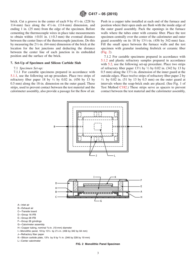
A—Inlet air
B—Exhaust air
C—Transite board
D—Group 16 IFB
E—Group 28 IFB
F—Group 28 grindings
G—Calorimeter assembly
H—Copper tubing, nominal ⁄8-in. (10-mm) diameter
I—Center calorimeter
FIG. 1 Furnace Modification
the surface of the calorimeter. Copper tubing shall be placed within each hole so that a compressed-air source can be attached to
one side and flexible leads to a flowmeter can be attached to the other.
4.3 A compressed-air supply and flowmeter for air.
5. Test Specimens
1 1
5.1 Castable Refractories—The test specimens may consist of either a panel 18 by 13 ⁄2 by 2 ⁄2 in. (456 by 342 by 64 mm), or
1 1 1 1
an assembly of three straights 9 by 4 ⁄2 by 2 ⁄2 in. (228 by 114 by 64 mm) and six soaps 9 by 2 ⁄4 by 2 ⁄2 in. (228 by 57 by 64
mm). These specimens shall be prepared as in one of the following methods and in general accordance with the manufacturer’s
recommendation for water content and Practice C862.
1 1
5.1.1 Panel Specimens—This test specimen shall be a monolithic panel 18 by 13 ⁄2 by 2 ⁄2 in. (456 by 342 by 64 mm) in size,
and shall be prepared in general accordance with Practice C862, as outlined in 5.1. The panel shall be cast in a steel mold with
two steel rods (Note 1) taped in place at the center line of the 18-in. (456-mm) length of the mold cavity. These steel rods form
the slot required so that the panel will fit over the tubing used for the entrance and exhaust of air and moisture from the furnace
(see Fig. 1).
1 1
NOTE 1—Two ⁄2-in. (13-mm) diameter steel rods 2 in. (51 mm) long should have approximately ⁄32 in. (0.8 mm) removed longitudinally to provide
a flat base.
1 1
5.1.2 Straight Specimens—This test specimen shall be three 9 by 4 ⁄2 by 2 ⁄2-in. (228 by 114 by 64-mm) straight brick and six
1 1
9 by 2 ⁄4 by 2 ⁄2-in. (228 by 57 by 64-mm) soap brick and shall be prepared in accordance with Practice C862, as outlined in 5.1
1 1
and 5.1.1, and by cutting as required. The 9 by 4 ⁄2-in. (228 by 114-mm) face of the three straight brick and the 9 by 2 ⁄4-in. face
of the soap brick shall be flat and parallel, and the thickness shall not vary more than 60.01 in. (60.3 mm). No grinding of the
C417 − 05 (2015)
finish face is required if care is taken when removing the excess mix with the strikeoff bar and slicking the exposed surface with
a minimum amount of troweling. Steel rods (described in Note 1) shall be used in two cavities to provide the required slots for
air entry and exit.
5.2 Plastic Refractories—The test specimens shall be of the size and number described in 4.1 of Test Method C201, and shall
be prepared in accordance with Practice C1054 and 3.2 of Test Method C201. The soap specimens shall be prepared by cutting
dry 9-in. (228-mm) straight specimens with a suitable abrasive cut-off saw. The soap brick adjacent to the 9-in. (228-mm) face of
the guard brick shall be slotted with a suitable abrasive cut-off saw at the center line of the 9-in. (228-mm) length to fit over the
tubing used for the entrance, and exhaust of the air and moisture.
5.3 Specimen Curing and Drying—After the specified curing, the specimens shall be placed in a dryer at 250°F (120°C) for a
minimum of 24 h, or until constant mass has been achieved.
6. Installation of Thermocouples in Test Specimen
6.1 Thermocouples—Embed calibrated thermocouples in the test specimen at two points for measurement of temperature. Use
platinum-10 % rhodium/platinum, Awg Gauge 28 (0.320-mm) wire in making the thermocouples.
6.2 Installation of Thermocouples:
6.2.1 For castable specimens prepared in accordance with 5.1.1, use the following thermocouple installation procedure. Place
the hot junction of the thermocouples in the center of each 18 by 13 ⁄2-in. (456 by 342-mm) face and just below the surface of
1 1
the test specimen. Cut grooves to receive the wire in each 18 by 13 ⁄2-in. (456 by 342-mm) face to a depth of ⁄32 in. (0.8 mm)
by means of an abrasive wheel 0.02 in. (0.5 mm) in thickness. The layout for the grooves allows all of the cold-junction ends of
the wires to extend from one end of the specimen. Cut a groove in the center of each 18 by 13 ⁄2-in. (456 by 342-mm) face along
the 18-in. (456-mm) dimension and ending 1 ⁄2 in. (38 mm) from the center point of the specimen. Extend the path of each groove
1 1
at an angle of 90° to one end of the specimen by cutting grooves parallel to the 13 ⁄2-in. (342-mm) edges and 1 ⁄2 in. (3.8 mm)
from the center point of the specimen. Before cementing the thermocouple wires in place, take measurements to obtain, within 0.01
in. (0.3 mm), the eventual distance between the center lines of the thermocouple junctions. Do this by measuring the 2 ⁄2-in.
(64-mm) dimension of the specimens at the location for the hot junctions and deducting the distance between the center line of
each junction in its embedded position and the surface of the specimen.
6.2.2 For castable specimens prepared in accordance with 5.1.2 and plastic refractory specimens prepared in accordance with
5.2, use the following thermocouple installation procedure. Place the hot junction of the thermocouples in the center of each 9 by
1 1
4 ⁄2-in. (228 by 114-mm) face, and just below the surface of the test specimen. Cut grooves to receive the wire in each 9 by 4 ⁄2-in.
(228 by 114-mm) face of the brick to a depth of ⁄32 in. (0.8 mm) by means of an abrasive wheel 0.02 in. (0.5 mm) in thickness.
The layout for the grooves allows all of the cold-junction ends of the wires to extend from one end of the brick. Cut a groove in
1 1
the center of each 9 by 4 ⁄2-in. (228 by 114-mm) face along the 4 ⁄2-in. (114-mm) dimension, and ending 1 in. (25 mm) from the
edge of the specimen. Before cementing the thermocouple wires in place take measurements to obtain within 60.01 in. (60.3 mm)
th
...
Questions, Comments and Discussion
Ask us and Technical Secretary will try to provide an answer. You can facilitate discussion about the standard in here.