


ASTM E1222-90(2016)
(Test Method)Standard Test Method for Laboratory Measurement of the Insertion Loss of Pipe Lagging Systems
Standard Test Method for Laboratory Measurement of the Insertion Loss of Pipe Lagging Systems
SIGNIFICANCE AND USE
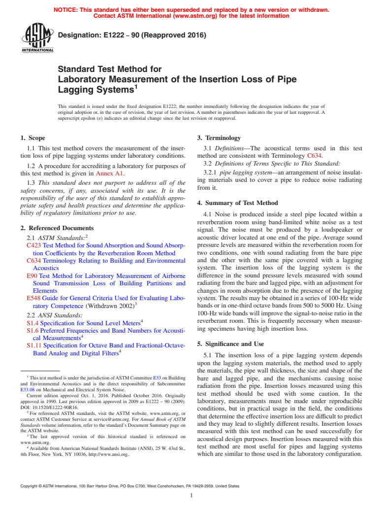
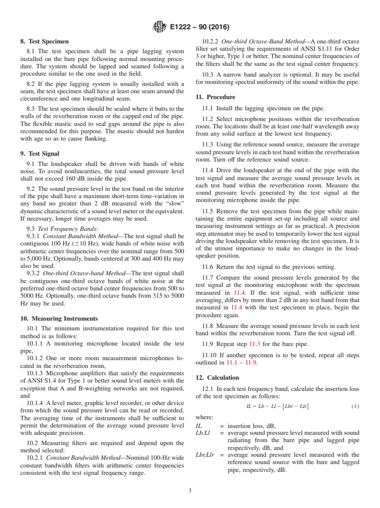
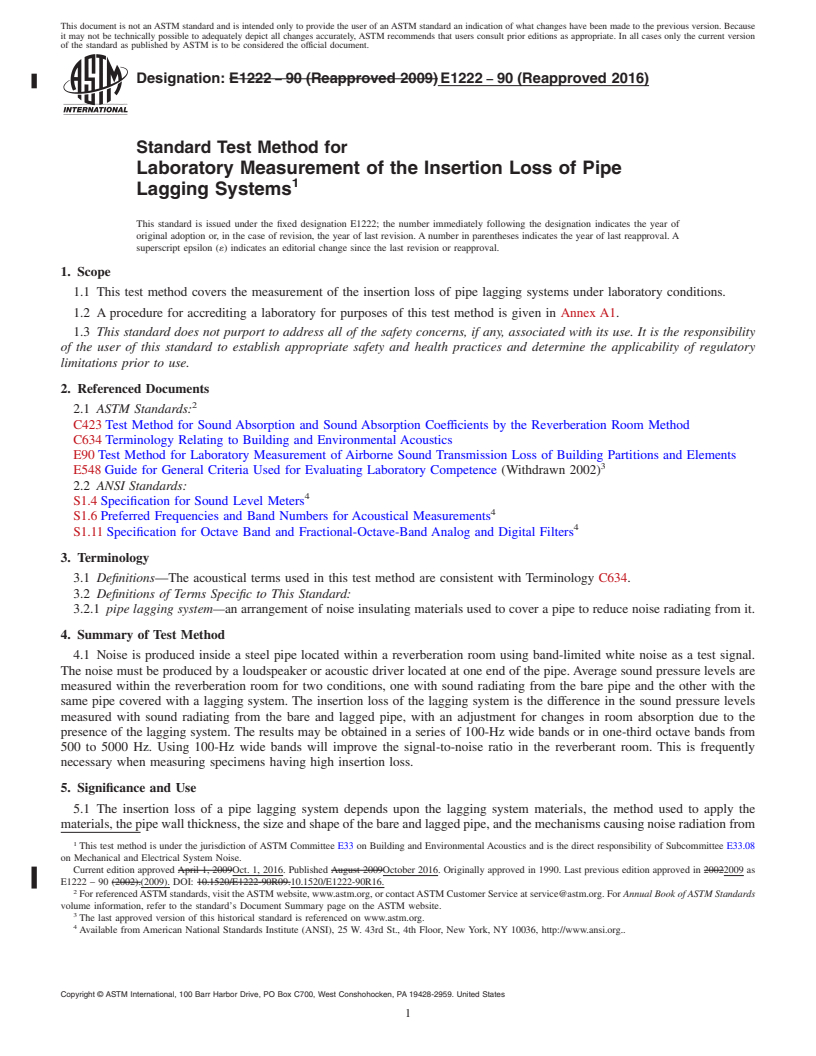
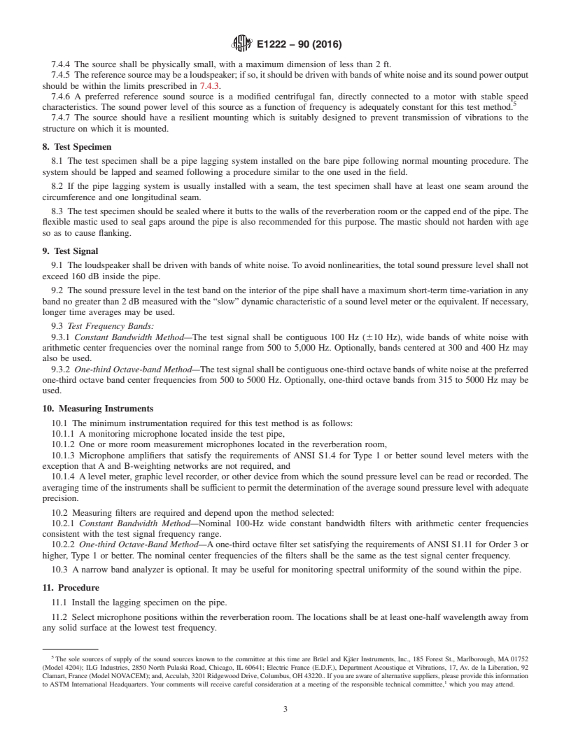
5.1 The insertion loss of a pipe lagging system depends upon the lagging system materials, the method used to apply the materials, the pipe wall thickness, the size and shape of the bare and lagged pipe, and the mechanisms causing noise radiation from the pipe. Insertion losses measured using this test method should be used with some caution. In the laboratory, measurements must be made under reproducible conditions, but in practical usage in the field, the conditions that determine the effective insertion loss are difficult to predict and they may lead to slightly different results. Insertion losses measured with this test method can be used successfully for acoustical design purposes. Insertion losses measured with this test method are most useful for pipes and lagging systems which are similar to those used in the laboratory configuration.
5.2 This test method may be used to rank-order pipe lagging systems according to insertion loss or to estimate the field insertion loss of pipe lagging systems installed in the field.
5.3 This test method assumes that pipe wall stresses resulting from different methods of supporting the test pipe in the laboratory do not have a significant effect upon the measured insertion loss.
5.4 Pipe lagging systems typically have small insertion loss, and sometimes negative insertion loss, at frequencies below 500 Hz. The results obtained at frequencies below 500 Hz may be somewhat erratic. Sound sources used with this test method normally have a low frequency limit in the range from 300 to 500 Hz. For these reasons, the lowest band of frequencies for which results are required is centered at 500 Hz.
SCOPE
1.1 This test method covers the measurement of the insertion loss of pipe lagging systems under laboratory conditions.
1.2 A procedure for accrediting a laboratory for purposes of this test method is given in Annex A1.
1.3 This standard does not purport to address all of the safety concerns, if any, associated with its use. It is the responsibility of the user of this standard to establish appropriate safety and health practices and determine the applicability of regulatory limitations prior to use.
General Information
Buy Standard
Standards Content (Sample)
NOTICE: This standard has either been superseded and replaced by a new version or withdrawn.
Contact ASTM International (www.astm.org) for the latest information
Designation: E1222 − 90 (Reapproved 2016)
Standard Test Method for
Laboratory Measurement of the Insertion Loss of Pipe
Lagging Systems
This standard is issued under the fixed designation E1222; the number immediately following the designation indicates the year of
original adoption or, in the case of revision, the year of last revision.Anumber in parentheses indicates the year of last reapproval.A
superscript epsilon (´) indicates an editorial change since the last revision or reapproval.
1. Scope 3. Terminology
1.1 This test method covers the measurement of the inser-
3.1 Definitions—The acoustical terms used in this test
tion loss of pipe lagging systems under laboratory conditions. method are consistent with Terminology C634.
3.2 Definitions of Terms Specific to This Standard:
1.2 Aprocedure for accrediting a laboratory for purposes of
3.2.1 pipe lagging system—anarrangementofnoiseinsulat-
this test method is given in Annex A1.
ing materials used to cover a pipe to reduce noise radiating
1.3 This standard does not purport to address all of the
from it.
safety concerns, if any, associated with its use. It is the
responsibility of the user of this standard to establish appro-
4. Summary of Test Method
priate safety and health practices and determine the applica-
bility of regulatory limitations prior to use.
4.1 Noise is produced inside a steel pipe located within a
reverberation room using band-limited white noise as a test
2. Referenced Documents
signal. The noise must be produced by a loudspeaker or
acoustic driver located at one end of the pipe. Average sound
2.1 ASTM Standards:
pressure levels are measured within the reverberation room for
C423TestMethodforSoundAbsorptionandSoundAbsorp-
two conditions, one with sound radiating from the bare pipe
tion Coefficients by the Reverberation Room Method
and the other with the same pipe covered with a lagging
C634Terminology Relating to Building and Environmental
Acoustics system. The insertion loss of the lagging system is the
difference in the sound pressure levels measured with sound
E90Test Method for Laboratory Measurement of Airborne
Sound Transmission Loss of Building Partitions and radiatingfromthebareandlaggedpipe,withanadjustmentfor
changes in room absorption due to the presence of the lagging
Elements
E548Guide for General Criteria Used for Evaluating Labo- system.Theresultsmaybeobtainedinaseriesof100-Hzwide
bandsorinone-thirdoctavebandsfrom500to5000Hz.Using
ratory Competence (Withdrawn 2002)
100-Hzwidebandswillimprovethesignal-to-noiseratiointhe
2.2 ANSI Standards:
reverberant room. This is frequently necessary when measur-
S1.4Specification for Sound Level Meters
ing specimens having high insertion loss.
S1.6Preferred Frequencies and Band Numbers forAcousti-
cal Measurements
5. Significance and Use
S1.11Specification for Octave Band and Fractional-Octave-
Band Analog and Digital Filters
5.1 The insertion loss of a pipe lagging system depends
upon the lagging system materials, the method used to apply
the materials, the pipe wall thickness, the size and shape of the
ThistestmethodisunderthejurisdictionofASTMCommitteeE33onBuilding
bare and lagged pipe, and the mechanisms causing noise
and Environmental Acoustics and is the direct responsibility of Subcommittee
radiation from the pipe. Insertion losses measured using this
E33.08 on Mechanical and Electrical System Noise.
test method should be used with some caution. In the
Current edition approved Oct. 1, 2016. Published October 2016. Originally
approved in 1990. Last previous edition approved in 2009 as E1222 – 90 (2009).
laboratory, measurements must be made under reproducible
DOI: 10.1520/E1222-90R16.
conditions, but in practical usage in the field, the conditions
For referenced ASTM standards, visit the ASTM website, www.astm.org, or
thatdeterminetheeffectiveinsertionlossaredifficulttopredict
contact ASTM Customer Service at service@astm.org. For Annual Book of ASTM
and they may lead to slightly different results. Insertion losses
Standards volume information, refer to the standard’s Document Summary page on
the ASTM website.
measured with this test method can be used successfully for
The last approved version of this historical standard is referenced on
acousticaldesignpurposes.Insertionlossesmeasuredwiththis
www.astm.org.
test method are most useful for pipes and lagging systems
Available fromAmerican National Standards Institute (ANSI), 25 W. 43rd St.,
4th Floor, New York, NY 10036, http://www.ansi.org. whicharesimilartothoseusedinthelaboratory configuration.
Copyright © ASTM International, 100 Barr Harbor Drive, PO Box C700, West Conshohocken, PA 19428-2959. United States
E1222 − 90 (2016)
5.2 Thistestmethodmaybeusedtorank-orderpipelagging sion. Any method of terminating the pipe may be used
systems according to insertion loss or to estimate the field provided that adequately low levels of flanking transmission
insertion loss of pipe lagging systems installed in the field. are achieved. It is usually necessary to cap the end of the pipe
within the reverberation room with heavy structure and to
5.3 This test method assumes that pipe wall stresses result-
vibration-isolatethepipeendfromthereverberationroomfloor
ing from different methods of supporting the test pipe in the
orceiling.Thecapmaybeablindflange,atleasttwiceasthick
laboratory do not have a significant effect upon the measured
as the pipe wall, welded to the end of the pipe.
insertion loss.
7.2.4 No solid connections may exist between the surfaces
5.4 Pipelaggingsystemstypicallyhavesmallinsertionloss,
of the reverberation room and the pipe or test specimen. A
and sometimes negative insertion loss, at frequencies below
flexible, nonhardening, knife grade mastic, such as available
500Hz.Theresultsobtainedatfrequenciesbelow500Hzmay
forsealinghigh-pressureducts,shouldbeusedtosealthegaps
be somewhat erratic. Sound sources used with this test method
where the pipe passes through walls.
normally have a low frequency limit in the range from 300 to
7.3 Loudspeaker:
500 Hz. For these reasons, the lowest band of frequencies for
which results are required is centered at 500 Hz.
7.3.1 Type—The loudspeaker may be a horn-driver combi-
nation or a direct radiator (cone type) loudspeaker. Normally,
6. Interferences
only acoustic drivers with horns will have sufficient output for
the tests when high insertion losses are being measured.
6.1 Flankingtransmissionmaylimitthemaximuminsertion
7.3.2 Installation—The loudspeaker shall be placed on the
losses which can be reliably measured using this test method.
open end of the pipe outside the reverberation room. The horn
The test pipe and reverberation room shall be constructed and
of the loudspeaker must be structurally isolated from any
arranged so as to minimize the possibility of transmission by
contact with the pipe wall.
paths other than through the test specimen. Flanking transmis-
sion should be at least 10 dB lower than the power transmitted
7.4 Reference Sound Source:
through the test specimen into the reverberation room. Appen-
7.4.1 A reference sound source is needed to permit adjust-
dix X1 presents one procedure for assessing flanking transmis-
mentsforthechangeinsoundabsorptionwithinthereverbera-
sion.
tion room due to the lagging system.
6.2 The background noise in each test band must be at least
7.4.2 The sound from the reference source shall be broad-
10 dB below measured sound pressure levels for that band.
band noise without significant single-frequency components.
The maximum sound power level of any single frequency
7. Apparatus
component within a band should be at least 5 dB below the
7.1 Reverberation Room—The sound field in the reverbera-
sound power level for that band.
tion room shall approximate a diffuse field when the test
7.4.3 The source level in any band shall have a maximum
specimen is in place. The requirements for the reverberation
short-term time-variation of no greater than 2 dB measured
room are in Test Method C423. The volume of the test room
with the slow dynamic characteristic of a sound level meter or
shall be 2000 ft or greater.
the equivalent.
7.1.1 The average sound absorption coefficients of the
7.4.4 Thesourceshallbephysicallysmall,withamaximum
room,excludingsoundabsorptionbyairandthetestspecimen,
dimension of less than 2 ft.
measured in accordance with Test Method C423, shall be less
7.4.5 The reference source may be a loudspeaker; if so, it
than0.06overthetestfrequencyrangewhenthetestspecimen
shouldbedrivenwithbandsofwhitenoiseanditssoundpower
is in place.
output should be within the limits prescribed in 7.4.3.
7.1.2 Diffusing devices such as rotating and stationary
7.4.6 A preferred reference sound source is a modified
diffusing surfaces are useful for creating an adequate diffuse
centrifugalfan,directlyconnectedtoamotorwithstablespeed
sound field.
characteristics. The sound power level of this source as a
7.2 Pipe:
function of frequency is adequately constant for this test
7.2.1 Construction—The standard test pipe shall be at least
method.
13 ft long and mounted horizontally within the reverberation
7.4.7 The source should have a resilient mounting which is
room. It shall be a nominal 12-in. diameter carbon steel pipe
suitably designed to prevent transmission of vibrations to the
with a nominal wall thickness of ⁄4 in.
structure on which it is mounted.
7.2.2 Other pipes may be used but they shall have a wall
thickness of at least ⁄4 in., a nominal diameter of at least 6 in.,
and shall be at least 13 diameters long.
Thesolesourcesofsupplyofthesoundsourcesknowntothecommitteeatthis
7.2.3 Installation—Potential flanking transmission can be
timeareBrüelandKjäerInstruments,Inc.,185ForestSt.,Marlborough,MA01752
minimized if both ends of the pipe are outside of the rever-
(Model 4204); ILG Industries, 2850 North Pulaski Road, Chicago, IL60641;
beration room. For this reason, this is the preferred method of
Electric France (E.D.F.), Department Acoustique et Vibrations, 17, Av. de la
Liberation, 92 Clamart, France (Model NOVACEM); and, Acculab, 3201 Ridge-
installing the pipe.Alternately, the loudspeaker end of the pipe
woodDrive,Columbus,OH43220.Ifyouareawareofalternativesuppliers,please
may be located outside of the reverberation room. In this case,
provide this information toASTM International Headquarters.Your comments will
theotherendofthepipewithinthereverberationroommustbe
receive careful consideration at a meeting of the responsible technical committee,
carefully constructed and mounted to avoid flanking transmis- which you may attend.
E1222 − 90 (2016)
8. Test Specimen 10.2.2 One-third Octave-Band Method—Aone-third octave
filter set satisfying the requirements of ANSI S1.11 for Order
8.1 The test specimen shall be a pipe lagging system
3orhigher,Type1orbetter.Thenominalcenterfrequenciesof
installed on the bare pipe following normal mounting proce-
the filters shall be the same as the test signal center frequency.
dure. The system should be lapped and seamed following a
procedure similar to the one used in the field.
10.3 A narrow band analyzer is optional. It may be useful
formonitoringspectraluniformityofthesoundwithinthepipe.
8.2 If the pipe lagging system is usually installed with a
seam,thetestspecimenshallhaveatleastoneseamaroundthe
11. Procedure
circumference and one longitudinal seam.
11.1 Install the lagging specimen on the pipe.
8.3 The test specimen should be sealed where it butts to the
walls of the reverberation room or the capped end of the pipe.
11.2 Select microphone positions within the reverberation
The flexible mastic used to seal gaps around the pipe is also
room.Thelocationsshallbeatleastone-halfwavelengthaway
recommended for this purpose. The mastic should not harden
from any solid surface at the lowest test frequency.
with age so as to cause flanking.
11.3 Usingthereferencesoundsource,measuretheaverage
soundpressurelevelsineachtestbandwithinthereverberation
9. Test Signal
room. Turn off the reference sound source.
9.1 The loudspeaker shall be driven with bands of white
11.4 Drive the loudspeaker at the end of the pipe with the
noise. To avoid nonlinearities, the total sound pressure level
test signal and measure the average sound pressure levels in
shall not exceed 160 dB inside the pipe.
each test band within the reverberation room. Measure the
9.2 The sound pressure level in the test band on the interior
sound pressure levels generated by the test signal at the
of the pipe shall have a maximum short-term time-variation in
monitoring microphone inside the pipe.
any band no greater than 2 dB measured with the “slow”
11.5 Remove the test specimen from the pipe while main-
dynamiccharacteristicofasoundlevelmeterortheequivalent.
If necessary, longer time averages may be used. taining the entire equipment set-up including all source and
measuring instrument settings as far as practical. A precision
9.3 Test Frequency Bands:
stepattenuatormaybeusedtotemporarilylowerthetestsignal
9.3.1 Constant Bandwidth Method—The test signal shall be
drivingtheloudspeakerwhileremovingthetestspecimen.Itis
contiguous 100 Hz (610 Hz), wide bands of white noise with
of the utmost importance to make no changes in the loud-
arithmetic center frequencies over the nominal range from 500
speaker position.
to5,000Hz.Optionally,bandscenteredat300and400Hzmay
also be used.
11.6 Return the test signal to the previous setting.
9.3.2 One-third Octave-band Method—The test signal shall
11.7 Compare the sound pressure levels generated by the
be contiguous one-third octave bands of white noise at the
test signal at the monitoring microphone with the spectrum
preferredone-thirdoctavebandcenterfrequenciesfrom500to
measured in 11.4. If the test signal, with sufficient time
5000 Hz. Optionally, one-third octave bands from 315 to 5000
averaging,differsbymorethan2dBinanytestbandfromthat
Hz may be used.
measured in 11.4 with the test specimen in place, begin the
procedure again.
10. Measuring Instruments
11.8 Measure the average sound pressure levels in each test
10.1 The minimum instrumentation required for this test
band within the reverberation room. Turn the test signal off.
method is as follows:
10.1.1 A monitoring microphone located inside the test
11.9 Repeat step 11.3 for the bare pipe.
pipe,
11.10 If another specimen is to be tested, repeat all steps
10.1.2 One or more room measurement microphones lo-
outlined in 11.1 – 11.9.
cated in the reverberation room,
10.1.3 Microphone amplifiers that satisfy the requirements
12. Calculation
ofANSI S1.4 for Type 1 or better sound level meters with the
exception that A and B-weighting networks are not required,
12.1 Ineachtestfrequencyband,calculatetheinsert
...
This document is not an ASTM standard and is intended only to provide the user of an ASTM standard an indication of what changes have been made to the previous version. Because
it may not be technically possible to adequately depict all changes accurately, ASTM recommends that users consult prior editions as appropriate. In all cases only the current version
of the standard as published by ASTM is to be considered the official document.
Designation: E1222 − 90 (Reapproved 2009) E1222 − 90 (Reapproved 2016)
Standard Test Method for
Laboratory Measurement of the Insertion Loss of Pipe
Lagging Systems
This standard is issued under the fixed designation E1222; the number immediately following the designation indicates the year of
original adoption or, in the case of revision, the year of last revision. A number in parentheses indicates the year of last reapproval. A
superscript epsilon (´) indicates an editorial change since the last revision or reapproval.
1. Scope
1.1 This test method covers the measurement of the insertion loss of pipe lagging systems under laboratory conditions.
1.2 A procedure for accrediting a laboratory for purposes of this test method is given in Annex A1.
1.3 This standard does not purport to address all of the safety concerns, if any, associated with its use. It is the responsibility
of the user of this standard to establish appropriate safety and health practices and determine the applicability of regulatory
limitations prior to use.
2. Referenced Documents
2.1 ASTM Standards:
C423 Test Method for Sound Absorption and Sound Absorption Coefficients by the Reverberation Room Method
C634 Terminology Relating to Building and Environmental Acoustics
E90 Test Method for Laboratory Measurement of Airborne Sound Transmission Loss of Building Partitions and Elements
E548 Guide for General Criteria Used for Evaluating Laboratory Competence (Withdrawn 2002)
2.2 ANSI Standards:
S1.4 Specification for Sound Level Meters
S1.6 Preferred Frequencies and Band Numbers for Acoustical Measurements
S1.11 Specification for Octave Band and Fractional-Octave-Band Analog and Digital Filters
3. Terminology
3.1 Definitions—The acoustical terms used in this test method are consistent with Terminology C634.
3.2 Definitions of Terms Specific to This Standard:
3.2.1 pipe lagging system—an arrangement of noise insulating materials used to cover a pipe to reduce noise radiating from it.
4. Summary of Test Method
4.1 Noise is produced inside a steel pipe located within a reverberation room using band-limited white noise as a test signal.
The noise must be produced by a loudspeaker or acoustic driver located at one end of the pipe. Average sound pressure levels are
measured within the reverberation room for two conditions, one with sound radiating from the bare pipe and the other with the
same pipe covered with a lagging system. The insertion loss of the lagging system is the difference in the sound pressure levels
measured with sound radiating from the bare and lagged pipe, with an adjustment for changes in room absorption due to the
presence of the lagging system. The results may be obtained in a series of 100-Hz wide bands or in one-third octave bands from
500 to 5000 Hz. Using 100-Hz wide bands will improve the signal-to-noise ratio in the reverberant room. This is frequently
necessary when measuring specimens having high insertion loss.
5. Significance and Use
5.1 The insertion loss of a pipe lagging system depends upon the lagging system materials, the method used to apply the
materials, the pipe wall thickness, the size and shape of the bare and lagged pipe, and the mechanisms causing noise radiation from
This test method is under the jurisdiction of ASTM Committee E33 on Building and Environmental Acoustics and is the direct responsibility of Subcommittee E33.08
on Mechanical and Electrical System Noise.
Current edition approved April 1, 2009Oct. 1, 2016. Published August 2009October 2016. Originally approved in 1990. Last previous edition approved in 20022009 as
E1222 – 90 (2002).(2009). DOI: 10.1520/E1222-90R09.10.1520/E1222-90R16.
For referenced ASTM standards, visit the ASTM website, www.astm.org, or contact ASTM Customer Service at service@astm.org. For Annual Book of ASTM Standards
volume information, refer to the standard’s Document Summary page on the ASTM website.
The last approved version of this historical standard is referenced on www.astm.org.
Available from American National Standards Institute (ANSI), 25 W. 43rd St., 4th Floor, New York, NY 10036, http://www.ansi.org.
Copyright © ASTM International, 100 Barr Harbor Drive, PO Box C700, West Conshohocken, PA 19428-2959. United States
E1222 − 90 (2016)
the pipe. Insertion losses measured using this test method should be used with some caution. In the laboratory, measurements must
be made under reproducible conditions, but in practical usage in the field, the conditions that determine the effective insertion loss
are difficult to predict and they may lead to slightly different results. Insertion losses measured with this test method can be used
successfully for acoustical design purposes. Insertion losses measured with this test method are most useful for pipes and lagging
systems which are similar to those used in the laboratory configuration.
5.2 This test method may be used to rank-order pipe lagging systems according to insertion loss or to estimate the field insertion
loss of pipe lagging systems installed in the field.
5.3 This test method assumes that pipe wall stresses resulting from different methods of supporting the test pipe in the laboratory
do not have a significant effect upon the measured insertion loss.
5.4 Pipe lagging systems typically have small insertion loss, and sometimes negative insertion loss, at frequencies below 500
Hz. The results obtained at frequencies below 500 Hz may be somewhat erratic. Sound sources used with this test method normally
have a low frequency limit in the range from 300 to 500 Hz. For these reasons, the lowest band of frequencies for which results
are required is centered at 500 Hz.
6. Interferences
6.1 Flanking transmission may limit the maximum insertion losses which can be reliably measured using this test method. The
test pipe and reverberation room shall be constructed and arranged so as to minimize the possibility of transmission by paths other
than through the test specimen. Flanking transmission should be at least 10 dB lower than the power transmitted through the test
specimen into the reverberation room. Appendix X1 presents one procedure for assessing flanking transmission.
6.2 The background noise in each test band must be at least 10 dB below measured sound pressure levels for that band.
7. Apparatus
7.1 Reverberation Room—The sound field in the reverberation room shall approximate a diffuse field when the test specimen
is in place. The requirements for the reverberation room are in Test Method C423. The volume of the test room shall be 2000 ft
or greater.
7.1.1 The average sound absorption coefficients of the room, excluding sound absorption by air and the test specimen, measured
in accordance with Test Method C423, shall be less than 0.06 over the test frequency range when the test specimen is in place.
7.1.2 Diffusing devices such as rotating and stationary diffusing surfaces are useful for creating an adequate diffuse sound field.
7.2 Pipe:
7.2.1 Construction—The standard test pipe shall be at least 13 ft long and mounted horizontally within the reverberation room.
It shall be a nominal 12-in. diameter carbon steel pipe with a nominal wall thickness of ⁄4 in.
7.2.2 Other pipes may be used but they shall have a wall thickness of at least ⁄4 in., a nominal diameter of at least 6 in., and
shall be at least 13 diameters long.
7.2.3 Installation—Potential flanking transmission can be minimized if both ends of the pipe are outside of the reverberation
room. For this reason, this is the preferred method of installing the pipe. Alternately, the loudspeaker end of the pipe may be located
outside of the reverberation room. In this case, the other end of the pipe within the reverberation room must be carefully
constructed and mounted to avoid flanking transmission. Any method of terminating the pipe may be used provided that adequately
low levels of flanking transmission are achieved. It is usually necessary to cap the end of the pipe within the reverberation room
with heavy structure and to vibration-isolate the pipe end from the reverberation room floor or ceiling. The cap may be a blind
flange, at least twice as thick as the pipe wall, welded to the end of the pipe.
7.2.4 No solid connections may exist between the surfaces of the reverberation room and the pipe or test specimen. A flexible,
nonhardening, knife grade mastic, such as available for sealing high-pressure ducts, should be used to seal the gaps where the pipe
passes through walls.
7.3 Loudspeaker:
7.3.1 Type—The loudspeaker may be a horn-driver combination or a direct radiator (cone type) loudspeaker. Normally, only
acoustic drivers with horns will have sufficient output for the tests when high insertion losses are being measured.
7.3.2 Installation—The loudspeaker shall be placed on the open end of the pipe outside the reverberation room. The horn of the
loudspeaker must be structurally isolated from any contact with the pipe wall.
7.4 Reference Sound Source:
7.4.1 A reference sound source is needed to permit adjustments for the change in sound absorption within the reverberation
room due to the lagging system.
7.4.2 The sound from the reference source shall be broadband noise without significant single-frequency components. The
maximum sound power level of any single frequency component within a band should be at least 5 dB below the sound power
level for that band.
7.4.3 The source level in any band shall have a maximum short-term time-variation of no greater than 2 dB measured with the
slow dynamic characteristic of a sound level meter or the equivalent.
E1222 − 90 (2016)
7.4.4 The source shall be physically small, with a maximum dimension of less than 2 ft.
7.4.5 The reference source may be a loudspeaker; if so, it should be driven with bands of white noise and its sound power output
should be within the limits prescribed in 7.4.3.
7.4.6 A preferred reference sound source is a modified centrifugal fan, directly connected to a motor with stable speed
characteristics. The sound power level of this source as a function of frequency is adequately constant for this test method.
7.4.7 The source should have a resilient mounting which is suitably designed to prevent transmission of vibrations to the
structure on which it is mounted.
8. Test Specimen
8.1 The test specimen shall be a pipe lagging system installed on the bare pipe following normal mounting procedure. The
system should be lapped and seamed following a procedure similar to the one used in the field.
8.2 If the pipe lagging system is usually installed with a seam, the test specimen shall have at least one seam around the
circumference and one longitudinal seam.
8.3 The test specimen should be sealed where it butts to the walls of the reverberation room or the capped end of the pipe. The
flexible mastic used to seal gaps around the pipe is also recommended for this purpose. The mastic should not harden with age
so as to cause flanking.
9. Test Signal
9.1 The loudspeaker shall be driven with bands of white noise. To avoid nonlinearities, the total sound pressure level shall not
exceed 160 dB inside the pipe.
9.2 The sound pressure level in the test band on the interior of the pipe shall have a maximum short-term time-variation in any
band no greater than 2 dB measured with the “slow” dynamic characteristic of a sound level meter or the equivalent. If necessary,
longer time averages may be used.
9.3 Test Frequency Bands:
9.3.1 Constant Bandwidth Method—The test signal shall be contiguous 100 Hz (610 Hz), wide bands of white noise with
arithmetic center frequencies over the nominal range from 500 to 5,000 Hz. Optionally, bands centered at 300 and 400 Hz may
also be used.
9.3.2 One-third Octave-band Method—The test signal shall be contiguous one-third octave bands of white noise at the preferred
one-third octave band center frequencies from 500 to 5000 Hz. Optionally, one-third octave bands from 315 to 5000 Hz may be
used.
10. Measuring Instruments
10.1 The minimum instrumentation required for this test method is as follows:
10.1.1 A monitoring microphone located inside the test pipe,
10.1.2 One or more room measurement microphones located in the reverberation room,
10.1.3 Microphone amplifiers that satisfy the requirements of ANSI S1.4 for Type 1 or better sound level meters with the
exception that A and B-weighting networks are not required, and
10.1.4 A level meter, graphic level recorder, or other device from which the sound pressure level can be read or recorded. The
averaging time of the instruments shall be sufficient to permit the determination of the average sound pressure level with adequate
precision.
10.2 Measuring filters are required and depend upon the method selected:
10.2.1 Constant Bandwidth Method—Nominal 100-Hz wide constant bandwidth filters with arithmetic center frequencies
consistent with the test signal frequency range.
10.2.2 One-third Octave-Band Method—A one-third octave filter set satisfying the requirements of ANSI S1.11 for Order 3 or
higher, Type 1 or better. The nominal center frequencies of the filters shall be the same as the test signal center frequency.
10.3 A narrow band analyzer is optional. It may be useful for monitoring spectral uniformity of the sound within the pipe.
11. Procedure
11.1 Install the lagging specimen on the pipe.
11.2 Select microphone positions within the reverberation room. The locations shall be at least one-half wavelength away from
any solid surface at the lowest test frequency.
The sole sources of supply of the sound sources known to the committee at this time are Brüel and Kjäer Instruments, Inc., 185 Forest St., Marlborough, MA 01752
(Model 4204); ILG Industries, 2850 North Pulaski Road, Chicago, IL 60641; Electric France (E.D.F.), Department Acoustique et Vibrations, 17, Av. de la Liberation, 92
Clamart, France (Model NOVACEM); and, Acculab, 3201 Ridgewood Drive, Columbus, OH 43220. If you are aware of alternative suppliers, please provide this information
to ASTM International Headquarters. Your comments will receive careful consideration at a meeting of the responsible technical committee, which you may attend.
E1222 − 90 (2016)
11.3 Using the reference sound source, measure the average sound pressure levels in each test band within the reverberation
room. Turn off the reference sound source.
11.4 Drive the loudspeaker at the end of th
...
Questions, Comments and Discussion
Ask us and Technical Secretary will try to provide an answer. You can facilitate discussion about the standard in here.