


ASTM C704/C704M-15(2022)
(Test Method)Standard Test Method for Abrasion Resistance of Refractory Materials at Room Temperature
Standard Test Method for Abrasion Resistance of Refractory Materials at Room Temperature
SIGNIFICANCE AND USE
4.1 This test method measures the relative abrasion resistance of various refractory samples under standard conditions at room temperature.
4.2 The abrasion resistance of a refractory material provides an indication of its suitability for service in abrasive environments.
4.3 The results obtained by this test method could be different than those obtained in service because of the different conditions encountered.
SCOPE
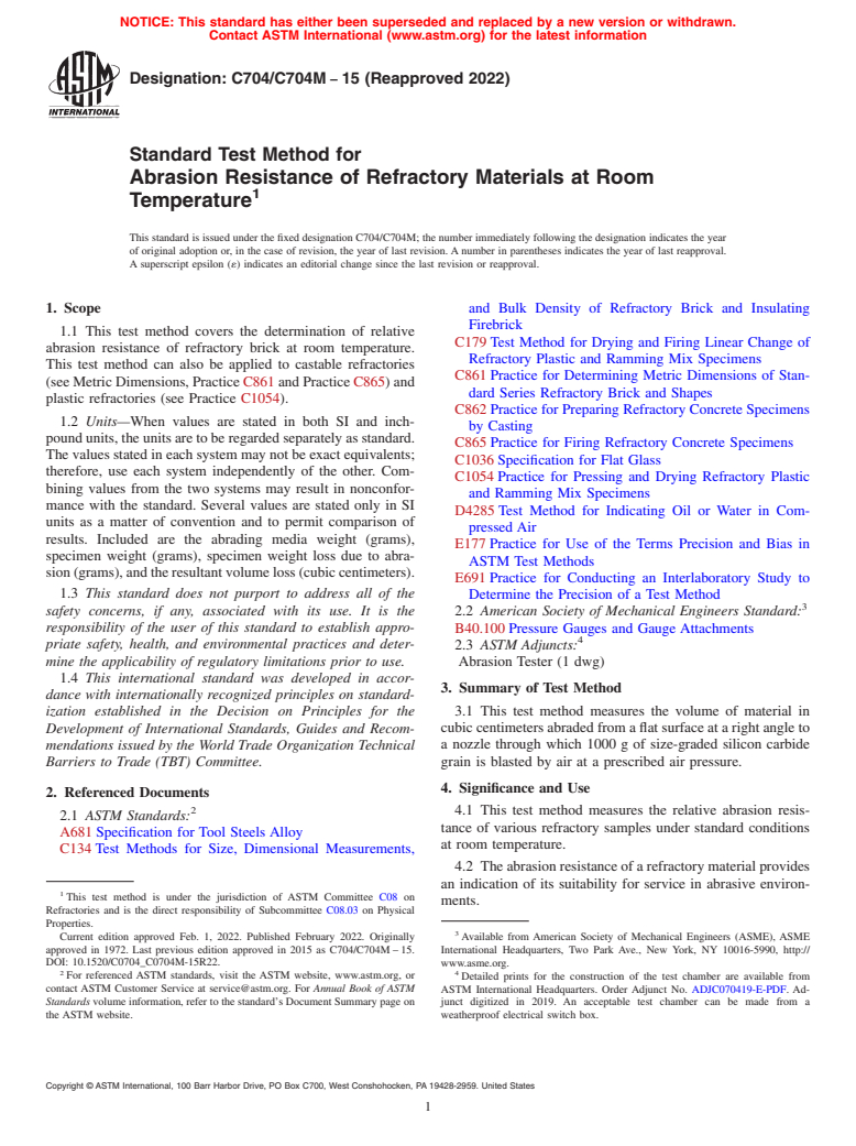
1.1 This test method covers the determination of relative abrasion resistance of refractory brick at room temperature. This test method can also be applied to castable refractories (see Metric Dimensions, Practice C861 and Practice C865) and plastic refractories (see Practice C1054).
1.2 Units—When values are stated in both SI and inch-pound units, the units are to be regarded separately as standard. The values stated in each system may not be exact equivalents; therefore, use each system independently of the other. Combining values from the two systems may result in nonconformance with the standard. Several values are stated only in SI units as a matter of convention and to permit comparison of results. Included are the abrading media weight (grams), specimen weight (grams), specimen weight loss due to abrasion (grams), and the resultant volume loss (cubic centimeters).
1.3 This standard does not purport to address all of the safety concerns, if any, associated with its use. It is the responsibility of the user of this standard to establish appropriate safety, health, and environmental practices and determine the applicability of regulatory limitations prior to use.
1.4 This international standard was developed in accordance with internationally recognized principles on standardization established in the Decision on Principles for the Development of International Standards, Guides and Recommendations issued by the World Trade Organization Technical Barriers to Trade (TBT) Committee.
General Information
Buy Standard
Standards Content (Sample)
NOTICE: This standard has either been superseded and replaced by a new version or withdrawn.
Contact ASTM International (www.astm.org) for the latest information
Designation: C704/C704M − 15 (Reapproved 2022)
Standard Test Method for
Abrasion Resistance of Refractory Materials at Room
Temperature
This standard is issued under the fixed designation C704/C704M; the number immediately following the designation indicates the year
of original adoption or, in the case of revision, the year of last revision.Anumber in parentheses indicates the year of last reapproval.
A superscript epsilon (´) indicates an editorial change since the last revision or reapproval.
1. Scope and Bulk Density of Refractory Brick and Insulating
Firebrick
1.1 This test method covers the determination of relative
C179Test Method for Drying and Firing Linear Change of
abrasion resistance of refractory brick at room temperature.
Refractory Plastic and Ramming Mix Specimens
This test method can also be applied to castable refractories
C861Practice for Determining Metric Dimensions of Stan-
(seeMetricDimensions,PracticeC861andPracticeC865)and
dard Series Refractory Brick and Shapes
plastic refractories (see Practice C1054).
C862Practice for Preparing Refractory Concrete Specimens
1.2 Units—When values are stated in both SI and inch-
by Casting
poundunits,theunitsaretoberegardedseparatelyasstandard.
C865Practice for Firing Refractory Concrete Specimens
Thevaluesstatedineachsystemmaynotbeexactequivalents;
C1036Specification for Flat Glass
therefore, use each system independently of the other. Com-
C1054Practice for Pressing and Drying Refractory Plastic
bining values from the two systems may result in nonconfor-
and Ramming Mix Specimens
mance with the standard. Several values are stated only in SI
D4285Test Method for Indicating Oil or Water in Com-
units as a matter of convention and to permit comparison of
pressed Air
results. Included are the abrading media weight (grams),
E177Practice for Use of the Terms Precision and Bias in
specimen weight (grams), specimen weight loss due to abra-
ASTM Test Methods
sion(grams),andtheresultantvolumeloss(cubiccentimeters).
E691Practice for Conducting an Interlaboratory Study to
1.3 This standard does not purport to address all of the Determine the Precision of a Test Method
safety concerns, if any, associated with its use. It is the
2.2 American Society of Mechanical Engineers Standard:
responsibility of the user of this standard to establish appro- B40.100Pressure Gauges and Gauge Attachments
priate safety, health, and environmental practices and deter-
2.3 ASTM Adjuncts:
mine the applicability of regulatory limitations prior to use.
Abrasion Tester (1 dwg)
1.4 This international standard was developed in accor-
3. Summary of Test Method
dance with internationally recognized principles on standard-
3.1 This test method measures the volume of material in
ization established in the Decision on Principles for the
Development of International Standards, Guides and Recom- cubiccentimetersabradedfromaflatsurfaceatarightangleto
a nozzle through which 1000 g of size-graded silicon carbide
mendations issued by the World Trade Organization Technical
Barriers to Trade (TBT) Committee. grain is blasted by air at a prescribed air pressure.
4. Significance and Use
2. Referenced Documents
2 4.1 This test method measures the relative abrasion resis-
2.1 ASTM Standards:
tance of various refractory samples under standard conditions
A681Specification for Tool Steels Alloy
at room temperature.
C134Test Methods for Size, Dimensional Measurements,
4.2 Theabrasionresistanceofarefractorymaterialprovides
an indication of its suitability for service in abrasive environ-
This test method is under the jurisdiction of ASTM Committee C08 on
ments.
Refractories and is the direct responsibility of Subcommittee C08.03 on Physical
Properties.
Current edition approved Feb. 1, 2022. Published February 2022. Originally Available from American Society of Mechanical Engineers (ASME), ASME
approved in 1972. Last previous edition approved in 2015 as C704/C704M–15. International Headquarters, Two Park Ave., New York, NY 10016-5990, http://
DOI: 10.1520/C0704_C0704M-15R22. www.asme.org.
2 4
For referenced ASTM standards, visit the ASTM website, www.astm.org, or Detailed prints for the construction of the test chamber are available from
contact ASTM Customer Service at service@astm.org. For Annual Book of ASTM ASTM International Headquarters. Order Adjunct No. ADJC070419-E-PDF. Ad-
Standards volume information, refer to the standard’s Document Summary page on junct digitized in 2019. An acceptable test chamber can be made from a
the ASTM website. weatherproof electrical switch box.
Copyright © ASTM International, 100 Barr Harbor Drive, PO Box C700, West Conshohocken, PA 19428-2959. United States
C704/C704M − 15 (2022)
4.3 The results obtained by this test method could be used, this will replace the steel nozzle supplied with the gun.
different than those obtained in service because of the different Cleanly cut the ends of the glass tube and do not fire polish
conditions encountered. them. Check the length and diameter of each tube prior to use.
The diameter may be checked by the use of a gauge consisting
5. Interferences (Factors Known to Affect Results)
of a tapered stainless steel rod with the 4.8 mm [ ⁄16 in.]
diameter marked on the rod. The glass tubing is held in place
5.1 During development, a ruggedness test was performed
1 1 1
bya70mm[2 ⁄4 in.] long piece of stainless steel or copper
using 114 by 114 by 12.7 mm [4 ⁄2 by 4 ⁄2 by ⁄2 in.] float glass
9 5
tubing with an inside diameter of 7.15 to 7.75 mm [ ⁄32 to ⁄8
platesconformingtoSpecificationC1036.Severalfactorswere
in.] and an outside diameter of 9.53 mm [ ⁄8 in.]. Flare the
found to cause statistically significant effects on measured
tubing at one end to sit snugly inside a 9.53 mm [ ⁄8 in.] tubing
results (see Section 10).
nut. This sleeve is glued or soldered in place inside the 9.53
5.1.1 Nozzle Tube Inside Diameter—Variation in the inside
mm [ ⁄8 in.] tubing nut, and is used primarily to hold the glass
diameter of the flint glass nozzle tube statistically affected the
tubing perpendicular to the test sample, ensuring a proper
abrasion values obtained on the glass plate. Ideal glass tube
vacuum within the gun. The end of the glass tube through
inside diameter is 4.8 mm. Glass tube lots purchased as 7 mm
which the abrading media enters the nozzle in the venturi
outside diameter tube with a nominal 1.1 mm wall thickness
chamber is inserted into a 15.9 mm [ ⁄8 in.] outside diameter,
canhaveinsidediametersrangingfrom4.6mmto5.0mm.For
6.4 mm [ ⁄4 in.] inside diameter rubber grommet with a
the ruggedness test, flint glass tube inside diameters of 4.7 mm
3 1
thickness of 4.75 to 6.4 mm [ ⁄16 to ⁄4 in.]. The glass tube is
and 4.9 mm were used. Take the statistically significant effect
of this small tube inside diameter variation into consideration. placed through the sleeve in the tubing nut, compressing the
grommet within the nut. The nut is attached to the gun. Fit the
Individuallymeasureandchooseallnozzletubestoconformto
a specified 4.8 mm inside diameter. nozzle tightly into the grommet in order to achieve adequate
vacuum (see 8.6). The glass tube is then positioned at a
5.1.2 Air Pressure—Variation in the test air pressure statis-
tically affected the abrasion values obtained on the glass plate. distance of 2 mm [0.08 in.] from the air-generator nozzle.This
is done by using a brass rod, 4.5 mm [0.175 in.] in diameter
Airpressureasspecifiedinthistestmethodis448kPa[65psi]
measured by a gauge capable to 66.9 kPa [61 psi]. For the withashoulder7.9mm[ ⁄16in.]indiameter,117mm[4.59in.]
from the tip and inserting this rod into the glass tube.This will
ruggedness test, air pressure was maintained at values of 441
allow the operator to push the glass tubing up until the rod
kPa [64 psi] and 455 kPa [66 psi] by the use of a calibrated
touchestheventuri,ensuringa2mm[0.08in.]gapbetweenthe
master series pressure gauge. Take the statistically significant
venturi and the glass tubing.
effectofthissmallairpressurevariationintoconsiderationand
use only gauges as specified in 6.1.5. It is also recommended
6.1.3 Venturi—The air generator nozzle dimensions are an
that air gauges be recalibrated at frequent intervals.
inlet inside diameter of 2.84 to 2.92 mm [0.112 to 0.115 in.]
and an outlet inside diameter of 2.36 to 2.44 mm [0.093 to
5.2 Factors that were found to be rugged during the test
0.096 in.]. Inspect the air generator nozzle for wear before any
method evaluation were: (1) particle size variation of the
test series and replace as necessary. The maximum inside
silicon carbide grain between sizings of grain composed of
diameter of the venturi chamber is 10 mm [ ⁄8 in.]. Check the
25% 20 mesh by 30 mesh and 75% 30 mesh by 50 mesh
inside diameter periodically for wear (Fig. 4).
silicon carbide to one composed of 15% 20 mesh by 30 mesh
6.1.4 Air Supply—Supply the abrasion gun with clean, dry
and85%30meshby50meshsiliconcarbidesizing,(2)nozzle
to sample distance varying between 200 mm [7 ⁄8 in.] to 206 air in accordance with Test Method D4285. The use of
appropriate drying equipment is necessary in order to achieve
mm [8 ⁄8 in.], (3) silicon carbide grit amount between 995 g
and 1005 g, and (4) test operator. consistent results. Ensure that the air supply is able to supply
an adequate volume of air such that the air pressure does not
6. Apparatus
fluctuate during the test run. If the air supply is also connected
to other equipment, ensure that the air supply is able to
6.1 Abrasion Tester, used for measuring the abrasion resis-
maintain consistent pressure throughout the test run, even
tance of refractory specimens, consisting of the following
when other equipment connected to the supply is operated.
(Figs. 1 and 2):
5 Consultation with an industrial professional in compressed air
6.1.1 Blast Gun (Leitch Carco Gun Model LC-CG) modi-
systems is recommended in setting up the air supply for the
fiedforthisequipmentasshowninFig.3.Othersandblastgun
abrasion tester.
models or types may affect test results.
6.1.5 Air Supply Pressure Gauge—Affixadialordigitaltest
6.1.2 Nozzle—Make the nozzle from a piece of flint-glass
pressure gauge meeting the requirements of ASME B40.100,
tubing, 115 mm [4 ⁄2 in.] long, 7 mm [0.276 in.] 6 0.12 mm
accuracy grade 3A, 60.25% of the span, to a fitting on top of
[0.005 in.] outside diameter, with a 1.1 mm [0.043 in.] 6 0.03
the gun as shown on Fig. 1. Recommended span is 0 to 1000
mm [0.001 in.] wall thickness. When the Carco Blast Gun is
kPa [0 to 100 psig] based on an anticipated air supply pressure
of 455 kPa [65 psig].
The sole source of supply of the apparatus known to the committee at this time
6.1.6 Abrading Media—New (unused), sharp (angular, jag-
is Leitch & Company, 106Abram Court, San Leandro, CA64577. If you are aware
ged edged grains), No. 36 grit silicon carbide containing
of alternative suppliers, please provide this information to ASTM International
minimal foreign material and having a screen analysis as
Headquarters.Your comments will receive careful consideration at a meeting of the
responsible technical committee, which you may attend. shown in Table 1. Verify the sizing of the grit by either user
C704/C704M − 15 (2022)
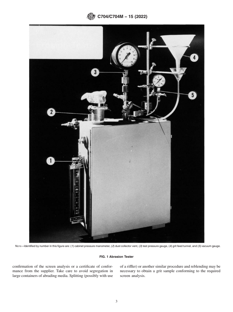
NOTE—Identified by number in this figure are: (1) cabinet pressure manometer, (2) dust collector vent, (3) test pressure gauge, (4) grit feed tunnel, and (5) vacuum gauge.
FIG. 1 Abrasion Tester
confirmation of the screen analysis or a certificate of confor- ofariffler)oranothersimilarprocedureandreblendingmaybe
mance from the supplier. Take care to avoid segregation in necessary to obtain a grit sample conforming to the required
largecontainersofabradingmedia.Splitting(possiblywithuse screen analysis.
C704/C704M − 15 (2022)
NOTE—Identified by number in this figure are: (1) sand blast gun, (2) air pressure regulator, (3) glass tube and metal stabilizing sleeve, (4) test sample, and (5) adjustable
platform.
FIG. 2 Abrasion Tester
6.1.7 Feeding Mechanism—Twoacceptablemechanismsfor 6.1.8 Test Chamber—Atightlysealedclosure withadoorto
feeding the abrading media are shown in Fig. 5. The feed
permit ready access for mounting and removing the test
funnel contains a suitable orifice to obtain a flow time of 450
specimens.Cuta13mm[ ⁄2in.]mountingholeinthetopofthe
6 15 s while delivering 1000 g of abrading media into the gun
test chamber to permit the vertical mounting of the blast gun
supply funnel. Metal, glass, or plastic orifices may be used to
such that the downward stream of abrading media will travel
regulatetheflow.Provideanairgapbetweentheorificeandthe
203 mm [8 in.] from the glass nozzle tip to the test specimen.
gun supply funnel to allow secondary air to enter with the 1
Equip the test chamber with a 52 mm [2 ⁄16 in.] exhaust with a
abrading media.
C704/C704M − 15 (2022)
NOTE—Identified by number in this figure are: (1) glass tube adjustment rod, (2) metal stabilizing sleeve, (3) glass tube with grommet, and (4) sand blast gun.
FIG. 3 Modified Blast Gun Breakdown
FIG. 4 Venturi Nozzle
butterfly valve to regulate the cabinet pressure. Figs. 1 and 2 6.1.8.1 Dust Collector—Adust-collectingclothorpaperbag
show the design of an acceptable chamber. of adequate capacity may be used on the exhaust port of the
C704/C704M − 15 (2022)
TABLE 1 Screen Analysis for Abrading Media
8.3 Placethenominal100by100mm[4by4in.]or114by
ASTM Standard 114 mm [4.5 by 4.5 in.] face of the test specimens at a 90°
Opening, µm Retained, %
Sieve No.
angle to the glass nozzle with the surface to be abraded 203
20 850 trace
mm [8 in.] from the tip of the glass nozzle. For brick samples,
30 600 20 ± 2
test an unbranded surface. For monolithic refractory
50 300 80 ± 3
70 212 2 max specimens, test the surface (that is, top free face or bottom
Pass No. 70 . . . trace
mold face) that most accurately reflects the actual field
situation.Normally,thefreesurfaceisthemostappropriatetest
surface. Position the specimen such that the abrasion pattern is
centered on the surface of the plate.
8.4 Turnontheairpressure.Regulatetheairpressureto448
chamber. Alternate dust handling systems such as venting to
kPa [65 psi]. Check the air pressure before and after the
the outside are acceptable as long as the chamber pressure is
abrading media is run through the system.
maintained at the desired level.
6.1.8.2 Chamber Pressure Manometer—Water manometer,
8.5 Measure the cabinet pressure using the manometer and
digital manometer, or magnehelic gauge with a span of 0 to 80
maintain the pressure in the cham
...
This document is not an ASTM standard and is intended only to provide the user of an ASTM standard an indication of what changes have been made to the previous version. Because
it may not be technically possible to adequately depict all changes accurately, ASTM recommends that users consult prior editions as appropriate. In all cases only the current version
of the standard as published by ASTM is to be considered the official document.
´1
Designation: C704/C704M − 15 C704/C704M − 15 (Reapproved 2022)
Standard Test Method for
Abrasion Resistance of Refractory Materials at Room
Temperature
This standard is issued under the fixed designation C704/C704M; the number immediately following the designation indicates the year
of original adoption or, in the case of revision, the year of last revision. A number in parentheses indicates the year of last reapproval.
A superscript epsilon (´) indicates an editorial change since the last revision or reapproval.
ε NOTE—Footnotes 3 and 4 were updated editorially in March 2019.
1. Scope
1.1 This test method covers the determination of relative abrasion resistance of refractory brick at room temperature. This test
method can also be applied to castable refractories (see Metric Dimensions, Practice C861 and Practice C865) and plastic
refractories (see Practice C1054).
1.2 Units—When values are stated in both SI and inch-pound units, the units are to be regarded separately as standard. The values
stated in each system may not be exact equivalents; therefore, use each system independently of the other. Combining values from
the two systems may result in nonconformance with the standard. Several values are stated only in SI units as a matter of
convention and to permit comparison of results. Included are the abrading media weight (grams), specimen weight (grams),
specimen weight loss due to abrasion (grams), and the resultant volume loss (cubic centimeters).
1.3 This standard does not purport to address all of the safety concerns, if any, associated with its use. It is the responsibility
of the user of this standard to establish appropriate safety, health, and environmental practices and determine the applicability of
regulatory limitations prior to use.
1.4 This international standard was developed in accordance with internationally recognized principles on standardization
established in the Decision on Principles for the Development of International Standards, Guides and Recommendations issued
by the World Trade Organization Technical Barriers to Trade (TBT) Committee.
2. Referenced Documents
2.1 ASTM Standards:
A681 Specification for Tool Steels Alloy
C134 Test Methods for Size, Dimensional Measurements, and Bulk Density of Refractory Brick and Insulating Firebrick
C179 Test Method for Drying and Firing Linear Change of Refractory Plastic and Ramming Mix Specimens
C861 Practice for Determining Metric Dimensions of Standard Series Refractory Brick and Shapes
C862 Practice for Preparing Refractory Concrete Specimens by Casting
C865 Practice for Firing Refractory Concrete Specimens
C1036 Specification for Flat Glass
C1054 Practice for Pressing and Drying Refractory Plastic and Ramming Mix Specimens
D4285 Test Method for Indicating Oil or Water in Compressed Air
E177 Practice for Use of the Terms Precision and Bias in ASTM Test Methods
This test method is under the jurisdiction of ASTM Committee C08 on Refractories and is the direct responsibility of Subcommittee C08.03 on Physical Properties.
Current edition approved March 1, 2015Feb. 1, 2022. Published April 2015February 2022. Originally approved in 1972. Last previous edition approved in 20142015 as
C704/C704M – 14.C704/C704M – 15. DOI: 10.1520/C0704_C0704M-15E01.10.1520/C0704_C0704M-15R22.
For referenced ASTM standards, visit the ASTM website, www.astm.org, or contact ASTM Customer Service at service@astm.org. For Annual Book of ASTM Standards
volume information, refer to the standard’s Document Summary page on the ASTM website.
Copyright © ASTM International, 100 Barr Harbor Drive, PO Box C700, West Conshohocken, PA 19428-2959. United States
C704/C704M − 15 (2022)
E691 Practice for Conducting an Interlaboratory Study to Determine the Precision of a Test Method
2.2 American Society of Mechanical Engineers Standard:
B40.100 Pressure Gauges and Gauge Attachments
2.3 ASTM Adjuncts:
Abrasion Tester (1 dwg)
3. Summary of Test Method
3.1 This test method measures the volume of material in cubic centimeters abraded from a flat surface at a right angle to a nozzle
through which 1000 g of size-graded silicon carbide grain is blasted by air at a prescribed air pressure.
4. Significance and Use
4.1 This test method measures the relative abrasion resistance of various refractory samples under standard conditions at room
temperature.
4.2 The abrasion resistance of a refractory material provides an indication of its suitability for service in abrasive environments.
4.3 The results obtained by this test method could be different than those obtained in service because of the different conditions
encountered.
5. Interferences (Factors Known to Affect Results)
1 1 1
5.1 During development, a ruggedness test was performed using 114 by 114 by 12.7 mm [4 ⁄2 by 4 ⁄2 by ⁄2 in.] float glass plates
conforming to Specification C1036. Several factors were found to cause statistically significant effects on measured results (see
Section 10).
5.1.1 Nozzle Tube Inside Diameter—Variation in the inside diameter of the flint glass nozzle tube statistically affected the abrasion
values obtained on the glass plate. Ideal glass tube inside diameter is 4.8 mm. Glass tube lots purchased as 7 mm outside diameter
tube with a nominal 1.1 mm wall thickness can have inside diameters ranging from 4.6 mm to 5.0 mm. For the ruggedness test,
flint glass tube inside diameters of 4.7 mm and 4.9 mm were used. Take the statistically significant effect of this small tube inside
diameter variation into consideration. Individually measure and choose all nozzle tubes to conform to a specified 4.8 mm inside
diameter.
5.1.2 Air Pressure—Variation in the test air pressure statistically affected the abrasion values obtained on the glass plate. Air
pressure as specified in this test method is 448 kPa [65 psi] measured by a gauge capable to 66.9 kPa [61 psi]. For the ruggedness
test, air pressure was maintained at values of 441 kPa [64 psi] and 455 kPa [66 psi] by the use of a calibrated master series pressure
gauge. Take the statistically significant effect of this small air pressure variation into consideration and use only gauges as specified
in 6.1.5. It is also recommended that air gauges be recalibrated at frequent intervals.
5.2 Factors that were found to be rugged during the test method evaluation were: ((1)1) particle size variation of the silicon carbide
grain between sizings of grain composed of 25%25 % 20 mesh by 30 mesh and 75%75 % 30 mesh by 50 mesh silicon carbide
to one composed of 15%15 % 20 mesh by 30 mesh and 85%85 % 30 mesh by 50 mesh silicon carbide sizing, ((2)2) nozzle to
7 1
sample distance varying between 200 mm [7 ⁄8 in.] to 206 mm [8 ⁄8 in.], ((3)3) silicon carbide grit amount between 995 g and 1005
g, and ((4)4) test operator.
6. Apparatus
6.1 Abrasion Tester, used for measuring the abrasion resistance of refractory specimens, consisting of the following (Fig. 1Figs.
1 and 2 and Fig. 2):
Available from American Society of Mechanical Engineers (ASME), ASME International Headquarters, Two Park Ave., New York, NY 10016-5990, http://
www.asme.org.
Detailed prints for the construction of the test chamber are available from ASTM International Headquarters. Order Adjunct No. ADJC070419-E-PDF. Adjunct digitized
in 2019. An acceptable test chamber can be made from a weatherproof electrical switch box.
C704/C704M − 15 (2022)
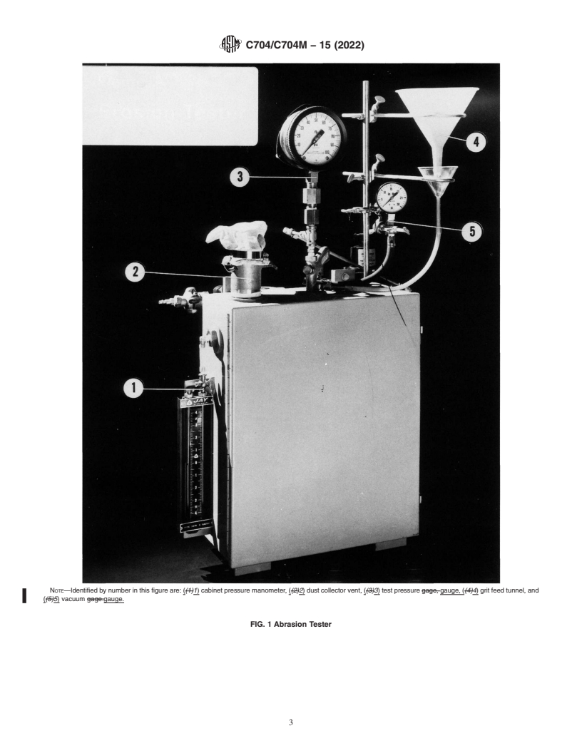
NOTE—Identified by number in this figure are: ((1)1) cabinet pressure manometer, ((2)2) dust collector vent, ((3)3) test pressure gage, gauge, ((4)4) grit feed tunnel, and
((5)5) vacuum gage.gauge.
FIG. 1 Abrasion Tester
C704/C704M − 15 (2022)
NOTE—Identified by number in this figure are: ((1)1) sand blast gun, ((2)2) air pressure regulator, ((3)3) glass tube and metal stabilizing sleeve, ((4)4) test sample, and
((5)5) adjustable platform.
FIG. 2 Abrasion Tester
6.1.1 Blast Gun (Leitch Carco Gun Model LC-CG) modified for this equipment as shown in Fig. 3. Other sand blast gun models
or types may affect test results.
6.1.2 Nozzle—Make the nozzle from a piece of flint-glass tubing, 115 mm [4 ⁄2 in.] long, 7 mm [0.276 in.] 6 0.12 mm [0.005
in.] outside diameter, with a 1.1 mm [0.043 in.] 6 0.03 mm [0.001 in.] wall thickness. When the Carco Blast Gun is used, this
The sole source of supply of the apparatus known to the committee at this time is Leitch & Company, 106 Abram Court, San Leandro, CA 64577. If you are aware of
alternative suppliers, please provide this information to ASTM International Headquarters. Your comments will receive careful consideration at a meeting of the responsible
technical committee, which you may attend.
C704/C704M − 15 (2022)
NOTE—Identified by number in this figure are: ((1)1) glass tube adjustment rod, ((2)2) metal stabilizing sleeve, ((3)3) glass tube with grommet, and ((4) 4) sand blast gun.
FIG. 3 Modified Blast Gun Breakdown
will replace the steel nozzle supplied with the gun. Cleanly cut the ends of the glass tube and do not fire polish them. Check the
length and diameter of each tube prior to use. The diameter may be checked by the use of a gagegauge consisting of a tapered
3 3
stainless steel rod with the 4.8 mm ([ ⁄16 in.)in.] diameter marked on the rod. The glass tubing is held in place by a 70 mm (2[2 ⁄4
9 5
in.)in.] long piece of stainless steel or copper tubing with an inside diameter of 7.15 to 7.75 mm [ ⁄32 to ⁄8 in.] and an outside
3 3
diameter of 9.53 mm [ ⁄8 in.]. Flare the tubing at one end to sit snugly inside a 9.53 mm [ ⁄8 in.] tubing nut. This sleeve is glued
or soldered in place inside the 9.53 mm [ ⁄8 in.] tubing nut, and is used primarily to hold the glass tubing perpendicular to the test
sample, ensuring a proper vacuum within the gun. The end of the glass tube through which the abrading media enters the nozzle
5 1
in the venturi chamber is inserted into a 15.9 mm [ ⁄8 in.] outside diameter, 6.4 mm [ ⁄4 in.] inside diameter rubber grommet with
3 1
a thickness of 4.75 to 6.4 mm [ ⁄16 to ⁄4 in.]. The glass tube is placed through the sleeve in the tubing nut, compressing the grommet
within the nut. The nut is attached to the gun. Fit the nozzle tightly into the grommet in order to achieve adequate vacuum (see
8.6). The glass tube is then positioned at a distance of 2 mm [0.08 in.] from the air-generator nozzle. This is done by using a brass
rod, 4.5 mm [0.175 in.] in diameter with a shoulder 7.9 mm [ ⁄16 in.] in diameter, 117 mm [4.59 in.] from the tip and inserting this
rod into the glass tube. This will allow the operator to push the glass tubing up until the rod touches the venturi, ensuring a 2 mm
[0.08 in.] gap between the venturi and the glass tubing.
6.1.3 Venturi—The air generator nozzle dimensions are an inlet inside diameter of 2.84 to 2.92 mm [0.112 to 0.115 in.] and an
outlet inside diameter of 2.36 to 2.44 mm [0.093 to 0.096 in.]. Inspect the air generator nozzle for wear before any test series and
replace as necessary. The maximum inside diameter of the venturi chamber is 10 mm [ ⁄8 in.]. Check the inside diameter
periodically for wear (Fig. 4).
6.1.4 Air Supply—Supply the abrasion gun with clean, dry air in accordance with Test Method D4285. The use of appropriate
drying equipment is necessary in order to achieve consistent results. Ensure that the air supply is able to supply an adequate volume
of air such that the air pressure does not fluctuate during the test run. If the air supply is also connected to other equipment, ensure
C704/C704M − 15 (2022)
FIG. 4 Venturi Nozzle
that the air supply is able to maintain consistent pressure throughout the test run, even when other equipment connected to the
supply is operated. Consultation with an industrial professional in compressed air systems is recommended in setting up the air
supply for the abrasion tester.
6.1.5 Air Supply Pressure Gauge—Affix a dial or digital test pressure gauge meeting the requirements of ASME B40.100, accuracy
grade 3A, 60.25 % of the span, to a fitting on top of the gun as shown on Fig. 1. Recommended span is 0 to 1000 kPa [0 to 100
psig] based on an anticipated air supply pressure of 455 kPa [65 psig].
6.1.6 Abrading Media—New (unused), sharp (angular, jagged edged grains), No. 36 grit silicon carbide containing minimal
foreign material and having a screen analysis as shown in Table 1. Verify the sizing of the grit by either user confirmation of the
screen analysis or a certificate of conformance from the supplier. Take care to avoid segregation in large containers of abrading
media. Splitting (possibly with use of a riffler) or another similar procedure and reblending may be necessary to obtain a grit sample
conforming to the required screen analysis.
6.1.7 Feeding Mechanism—Two acceptable mechanisms for feeding the abrading media are shown in Fig. 5. The feed funnel
contains a suitable orifice to obtain a flow time of 450 6 15 s while delivering 1000 g of abrading media into the gun supply funnel.
Metal, glass, or plastic orifices may be used to regulate the flow. Provide an air gap between the orifice and the gun supply funnel
to allow secondary air to enter with the abrading media.
6.1.8 Test Chamber—A tightly sealed closure with a door to permit ready access for mounting and removing the test specimens.
Cut a 13-mm 13 mm [ ⁄2 in.] mounting hole in the top of the test chamber to permit the vertical mounting of the blast gun such
that the downward stream of abrading media will travel 203 mm [8 in.] from the glass nozzle tip to the test specimen. Equip the
test chamber with a 52 mm [2 ⁄16 in.] exhaust with a butterfly valve to regulate the cabinet pressure. Fig. 1Figs. 1 and 2 and Fig.
2show the design of an acceptable chamber.
6.1.8.1 Dust Collector—A dust-collecting cloth or paper bag of adequate capacity may be used on the exhaust port of the chamber.
Alternate dust handling systems such as venting to the outside are acceptable as long as the chamber pressure is maintained at the
desired level.
TABLE 1 Screen Analysis for Abrading Media
ASTM Standard
Opening, μm Retained, %
Sieve No.
20 850 trace
30 600 20 ± 2
50 300 80 ± 3
70 212 2 max
Pass No. 70 . . . trace
C704/C704M − 15 (2022)
NOTE—Identified by number in this figure are: ((1)1) main supply funnel
...
Questions, Comments and Discussion
Ask us and Technical Secretary will try to provide an answer. You can facilitate discussion about the standard in here.