


ASTM C133-97(2015)
(Test Method)Standard Test Methods for Cold Crushing Strength and Modulus of Rupture of Refractories
Standard Test Methods for Cold Crushing Strength and Modulus of Rupture of Refractories
SIGNIFICANCE AND USE
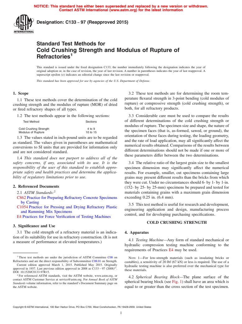
3.1 The cold strength of a refractory material is an indication of its suitability for use in refractory construction. (It is not a measure of performance at elevated temperatures.)
3.2 These test methods are for determining the room temperature flexural strength in 3-point bending (cold modulus of rupture) or compressive strength (cold crushing strength), or both, for all refractory products.
3.3 Considerable care must be used to compare the results of different determinations of the cold crushing strength or modulus of rupture. The specimen size and shape, the nature of the specimen faces (that is, as-formed, sawed, or ground), the orientation of those faces during testing, the loading geometry, and the rate of load application, may all significantly affect the numerical results obtained. Comparisons of the results between different determinations should not be made if one or more of these parameters differ between the two determinations.
3.4 The relative ratio of the largest grain size to the smallest specimen dimension may significantly affect the numerical results. For example, smaller, cut specimens containing large grains may present different results than the bricks from which they were cut. Under no circumstances should 6- by 1- by 1-in. (152- by 25- by 25-mm) specimens be prepared and tested for materials containing grains with a maximum grain dimension exceeding 0.25 in. (6.4 mm).
3.5 This test method is useful for research and development, engineering application and design, manufacturing process control, and for developing purchasing specifications.
SCOPE
1.1 These test methods cover the determination of the cold crushing strength and the modulus of rupture (MOR) of dried or fired refractory shapes of all types.
1.2 The test methods appear in the following sections:
Test Method
Sections
Cold Crushing Strength
4 to 9
Modulus of Rupture
10 to 15
1.3 The values stated in inch-pound units are to be regarded as standard. The values given in parentheses are mathematical conversions to SI units that are provided for information only and are not considered standard.
1.4 This standard does not purport to address all of the safety concerns, if any, associated with its use. It is the responsibility of the user of this standard to establish appropriate safety and health practices and determine the applicability of regulatory limitations prior to use.
General Information
Buy Standard
Standards Content (Sample)
NOTICE: This standard has either been superseded and replaced by a new version or withdrawn.
Contact ASTM International (www.astm.org) for the latest information
Designation: C133 − 97 (Reapproved 2015)
Standard Test Methods for
Cold Crushing Strength and Modulus of Rupture of
Refractories
This standard is issued under the fixed designation C133; the number immediately following the designation indicates the year of
original adoption or, in the case of revision, the year of last revision.Anumber in parentheses indicates the year of last reapproval.A
superscript epsilon (´) indicates an editorial change since the last revision or reapproval.
This standard has been approved for use by agencies of the U.S. Department of Defense.
1. Scope 3.2 These test methods are for determining the room tem-
perature flexural strength in 3-point bending (cold modulus of
1.1 These test methods cover the determination of the cold
rupture) or compressive strength (cold crushing strength), or
crushing strength and the modulus of rupture (MOR) of dried
both, for all refractory products.
or fired refractory shapes of all types.
1.2 The test methods appear in the following sections: 3.3 Considerable care must be used to compare the results
of different determinations of the cold crushing strength or
Test Method Sections
modulusofrupture.Thespecimensizeandshape,thenatureof
Cold Crushing Strength 4 to 9
the specimen faces (that is, as-formed, sawed, or ground), the
Modulus of Rupture 10 to 15
orientation of those faces during testing, the loading geometry,
1.3 The values stated in inch-pound units are to be regarded
and the rate of load application, may all significantly affect the
as standard. The values given in parentheses are mathematical
numericalresultsobtained.Comparisonsoftheresultsbetween
conversions to SI units that are provided for information only
different determinations should not be made if one or more of
and are not considered standard.
these parameters differ between the two determinations.
1.4 This standard does not purport to address all of the
safety concerns, if any, associated with its use. It is the 3.4 Therelativeratioofthelargestgrainsizetothesmallest
responsibility of the user of this standard to establish appro- specimen dimension may significantly affect the numerical
priate safety and health practices and determine the applica-
results. For example, smaller, cut specimens containing large
bility of regulatory limitations prior to use.
grains may present different results than the bricks from which
theywerecut.Undernocircumstancesshould6-by1-by1-in.
2. Referenced Documents
(152- by 25- by 25-mm) specimens be prepared and tested for
materials containing grains with a maximum grain dimension
2.1 ASTM Standards:
exceeding 0.25 in. (6.4 mm).
C862Practice for Preparing Refractory Concrete Specimens
by Casting
3.5 Thistestmethodisusefulforresearchanddevelopment,
C1054Practice for Pressing and Drying Refractory Plastic
engineering application and design, manufacturing process
and Ramming Mix Specimens
control, and for developing purchasing specifications.
E4Practices for Force Verification of Testing Machines
COLD CRUSHING STRENGTH
3. Significance and Use
3.1 The cold strength of a refractory material is an indica-
4. Apparatus
tionofitssuitabilityforuseinrefractoryconstruction.(Itisnot
4.1 Testing Machine—Any form of standard mechanical or
a measure of performance at elevated temperatures.)
hydraulic compression testing machine conforming to the
requirements of Practices E4 may be used.
These test methods are under the jurisdiction of ASTM Committee C08 on
NOTE 1—For low-strength materials (such as insulating bricks or
Refractories and are the direct responsibility of Subcommittee C08.01 on Strength.
castables), a sensitivity of 20 lbf (67 kN) or less is required. The use of a
Current edition approved March 1, 2015. Published May 2015. Originally
hydraulic testing machine is also preferred over the mechanical type for
ε1
approved in 1937. Last previous edition approved in 2008 as C133–97 (2008) .
these materials.
DOI: 10.1520/C0133-97R15.
For referenced ASTM standards, visit the ASTM website, www.astm.org, or
4.2 Spherical Bearing Block—The plane surface of the
contact ASTM Customer Service at service@astm.org. For Annual Book of ASTM
spherical bearing block (see Fig. 1) shall have an area which is
Standards volume information, refer to the standard’s Document Summary page on
the ASTM website. equal to or greater than the cross section of the test specimen.
Copyright © ASTM International, 100 Barr Harbor Drive, PO Box C700, West Conshohocken, PA 19428-2959. United States
C133 − 97 (2015)
6. Procedure
6.1 At least five specimens from an equivalent number of
refractory shapes compose a sample.
NOTE 2—For relatively weak specimens like insulating castables or
insulating firebricks, a minimum sample size of ten specimens is pre-
ferred.
6.2 Brick and Shapes—Place a cellulose fiber wall board
(for example, Masonite ) 0.25 in. (6.4 mm) in thickness and
extending 0.5 in. (12.7 mm) or more beyond the edges of the
loaded faces of the specimen. Apply the load parallel to the
direction in which the brick was originally pressed.
6.3 RegularandHighStrengthCastables—Placeacellulose
fiber wall board 0.25 in. (6.4 mm) in thickness and extending
0.5in.(12.7mm)ormorebeyondtheedgesoftheloadedfaces
of the specimen. Apply the load on the 2- by 2-in. (51- by
51-mm) or 2-in. (51-mm) diameter face and perpendicular to
FIG. 1 Recommended Design for Crushing Test Assembly, In-
cluding Bearing Block
the depth of the specimen as originally cast or gunned.
6.4 Insulating Brick or Shapes—Apply the load directly to
1 1
the 4 ⁄2-by4 ⁄2-in. (114- by 114-mm) surface of the test
specimen.
5. Test Specimens
6.5 Insulating Castables (typical bulk density of 100 lb/ft
3 3
5.1 Brick and Shapes (bulk density greater than 100 lb/ft (1.60 g/cm ), or greater than 45% total porosity, or both)—
(1.60 g/cm ))—The test specimens shall be 2-in. (51-mm)
Apply the load directly to the 2- by 2-in. (51- by 51-mm) face
cubes or cylinders, 2 in. (51 mm) in diameter by 2 in. (51 mm) and perpendicular to the depth of the specimen as originally
high. The height should be parallel to the original direction of cast or gunned.
pressing of the brick or shape. In the case of special shapes,
6.6 Use the bearing block on top of the test specimen, and
only one specimen shall be cut from a single shape and as
position it so that the center of the sphere is in alignment with
many of the original surfaces as possible shall be preserved. In
the vertical axis of the specimen (see Fig. 1). Keep the
preparing specimens from irregular or large refractory shapes,
spherical bearing block thoroughly lubricated to ensure accu-
any method involving the use of abrasives, such as a high-
rate adjustment which may be made by hand under a small
speed abrasion wheel, core drill, or rubbing bed, that will
initial load for each specimen.
produce a specimen with approximately plane and parallel
NOTE 3—The spherical bearing block may not be necessary on test
sides without weakening the structure of the specimen may be
machines having mechanical linkages which ensure that the stress applied
used.
is colinear with the axis of the specimen.
5.2 Insulating Brick or Shapes (typical bulk density of 100
6.7 For dense refractories with sufficient strength to require
3 3
lb/ft (1.60 g/cm ), or greater than 45% total porosity, or
greater than about 3 min per test, initial loading to one-half of
1 1 1
both)—The test specimens shall be 4 ⁄2 by 4 ⁄2 by 2 ⁄2 or 3 in.
the anticipated failure load may be accomplished at any
(114by114by64or76mm),eachtakenfromadifferentbrick.
convenient rate exceeding the specified rate. Subsequently,
Itispermissibletopreparethesespecimensfromthehalf-brick
each specimen shall be crushed with a compressive load
resulting from the modulus of rupture test (see Sections9–
appliedatthestandardratesspecifiedinTable1.Theratesshall
14). The selected compression test section shall be free of
not vary by more than 610% of the specified rate for the type
cracks, chipped surfaces, and other obvious defects. The test
of refractory being tested.
surfaces shall be approximately parallel planes.
6.8 When using a mechanical testing machine, keep the
5.3 Castable Refractories—The test specimens shall be 2- balance beam in a constantly floating position.
by 2- by 2-in. (51- by 51- by 51-mm) cubes or cylinders 2 in.
6.9 Specimens are loaded, as specified, to failure. Failure is
(51 mm) in diameter by 2 in. (51 mm) high, prepared by
defined as the collapse of the specimen (failure to support the
casting or gunning. It is permissible to prepare one specimen
load), or the reduction of the specimen height to 90% of its
from each 9- by 2- by 2-in. (230- by 51- by 51-mm) bar after
original value. The maximum applied load is recorded.
the modulus of rupture test (see Sections9–14). The selected
compression test section shall be free of cracks, chipped
7. Calculation
surfaces, and other obvious defects. The loaded surfaces shall
7.1 Calculate the cold crushing strength using Eq 1:
be approximately parallel planes.All samples must be dried at
S 5W/A (1)
220 to 230°F (105 to 110°C) for 18 h (overnight). Upon
removalfromtheoven,allowthesampletocoolnaturallyuntil
cool to the touch. Complete testing within2hof removal from
the drying oven. (See Practices C862 and C1054.) Masonite has been found satisfactory for this purpose.
C133 − 97 (2015)
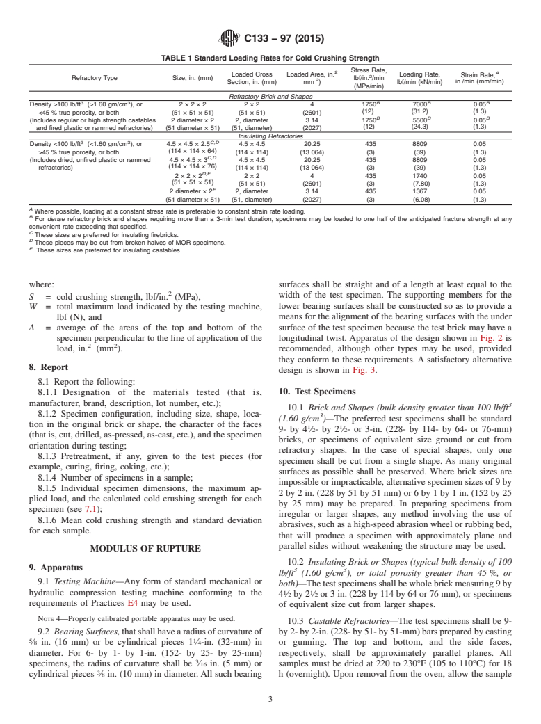
TABLE 1 Standard Loading Rates for Cold Crushing Strength
Stress Rate,
A
Loaded Cross Loaded Area, in. Loading Rate,
Strain Rate,
Refractory Type Size, in. (mm) lbf/in. /min
in./min (mm/min)
Section, in. (mm) mm ) lbf/min (kN/min)
(MPa/min)
Refractory Brick and Shapes
3 3 B B B
Density >100 lb/ft (>1.60 gm/cm ), or 2×2×2 2×2 4 1750 7000 0.05
(12) (31.2) (1.3)
<45 % true porosity, or both (51×51×51) (51 × 51) (2601)
B B B
(Includes regular or high strength castables 2 diameter × 2 2, diameter 3.14 1750 5500 0.05
(12) (24.3) (1.3)
and fired plastic or rammed refractories) (51 diameter × 51) (51, diameter) (2027)
Insulating Refractories
3 3 C,D
Density <100 lb/ft (<1.60 gm/cm ), or 4.5×4.5×2.5 4.5×4.5 20.25 435 8809 0.05
(114×114×64)
>45 % true porosity, or both (114 × 114) (13 064) (3) (39) (1.3)
C,D
(Includes dried, unfired plastic or rammed 4.5×4.5×3 4.5×4.5 20.25 435 8809 0.05
(114×114×76)
refractories) (114 × 114) (13 064) (3) (39) (1.3)
D,E
2×2×2 2×2 4 435 1740 0.05
(51×51×51)
(51 × 51) (2601) (3) (7.80) (1.3)
E
2 diameter × 2 2, diameter 3.14 435 1367 0.05
(51 diameter × 51) (51, diameter) (2027) (3) (6.08) (1.3)
A
Where possible, loading at a constant stress rate is preferable to constant strain rate loading.
B
For dense refractory brick and shapes requiring more than a 3-min test duration, specimens may be loaded to one half of the anticipated fracture strength at any
convenient rate exceeding that specified.
C
These sizes are preferred for insulating firebricks.
D
These pieces may be cut from broken halves of MOR specimens.
E
These sizes are preferred for insulating castables.
where: surfaces shall be straight and of a length at least equal to the
width of the test specimen. The supporting members for the
S = cold crushing strength, lbf/in. (MPa),
lower bearing surfaces shall be constructed so as to provide a
W = total maximum load indicated by the testing machine,
means for the alignment of the bearing surfaces with the under
lbf (N), and
A = average of the areas of the top and bottom of the surface of the test specimen because the test brick may have a
specimen perpendicular to the line of application of the longitudinal twist. Apparatus of the design shown in Fig. 2 is
2 2
load, in. (mm ). recommended, although other types may be used, provided
they conform to these requirements. A satisfactory alternative
8. Report
design is shown in Fig. 3.
8.1 Report the following:
10. Test Specimens
8.1.1 Designation of the materials tested (that is,
manufacturer, brand, description, lot number, etc.);
10.1 Brick and Shapes (bulk density greater than 100 lb/ft
8.1.2 Specimen configuration, including size, shape, loca-
(1.60 g/cm )—The preferred test specimens shall be standard
tion in the original brick or shape, the character of the faces
1 1
9- by 4 ⁄2-by2 ⁄2- or 3-in. (228- by 114- by 64- or 76-mm)
(thatis,cut,drilled,as-pressed,as-cast,etc.),andthespecimen
bricks, or specimens of equivalent size ground or cut from
orientation during testing;
refractory shapes. In the case of special shapes, only one
8.1.3 Pretreatment, if any, given to the test pieces (for
specimen shall be cut from a single shape. As many original
example, curing, firing, coking, etc.);
surfaces as possible shall be preserved. Where brick sizes are
8.1.4 Number of specimens in a sample;
impossible or impracticable, alternative specimen sizes of 9 by
8.1.5 Individual specimen dimensions, the maximum ap-
2 by 2 in. (228 by 51 by 51 mm) or 6 by 1 by 1 in. (152 by 25
plied load, and the calculated cold crushing strength for each
by 25 mm) may be prepared. In preparing specimens from
specimen (see 7.1);
irregular or larger shapes, any method involving the use of
8.1.6 Mean cold crushing strength and standard deviation
abrasives, such as a high-speed abrasion wheel or rubbing bed,
for each sample.
that will produce a specimen with approximately plane and
parallel sides without weakening the structure may be used.
MODULUS OF RUPTURE
10.2 Insulating Brick or Shapes (typical bulk density of 100
9. Apparatus
3 3
lb/ft (1.60 g/cm ), or total porosity greater than 45%, or
9.1 Testing Machine—Any form of standard mechanical or
both)—Thetestspecimensshallbewholebrickmeasuring9by
1 1
hydraulic compression testing machine conforming to the
4 ⁄2by2 ⁄2or3in.(228by114by64or76mm),orspecimens
requirements of Practices E4 may be used.
of equivalent size cut from larger shapes.
NOTE 4—Properly calibrated portable apparatus may be used.
10.3 Castable Refractories—The test specimens shall be 9-
9.2 BearingSurfaces,thatshallhavearadiusofcurvatureof by2-by2-in.(228-by51-by51-mm)barspreparedbycasting
5 1
⁄8 in. (16 mm) or be cylindrical pieces 1 ⁄4-in. (32-mm) in or gunning. The top and bottom, and the side faces,
diameter. For 6- by 1- by 1-in. (152- by 25- by 25-mm) respectively, shall be approximately parallel planes. All
specimens, the radius of curvature shall be ⁄16 in. (5 mm) or samples must be dried at 220 to 230°F (105 to 110°C) for 18
cylindrical pieces ⁄8 in. (10 mm) in diameter.All such bearing h (overnight). Upon removal from the oven, allow the sample
C133 − 97 (2015)
NOTE 1—The dimensions appearing in Fig. 2 are in inches. See table below for metric equivalents.
in. mm in. mm
3 1
⁄16 51 ⁄2 38
⁄4 62 51
⁄8 10 3 76
⁄2 13 4 102
5 1
⁄8 16
...
This document is not an ASTM standard and is intended only to provide the user of an ASTM standard an indication of what changes have been made to the previous version. Because
it may not be technically possible to adequately depict all changes accurately, ASTM recommends that users consult prior editions as appropriate. In all cases only the current version
of the standard as published by ASTM is to be considered the official document.
´1
Designation: C133 − 97 (Reapproved 2008) C133 − 97 (Reapproved 2015)
Standard Test Methods for
Cold Crushing Strength and Modulus of Rupture of
Refractories
This standard is issued under the fixed designation C133; the number immediately following the designation indicates the year of
original adoption or, in the case of revision, the year of last revision. A number in parentheses indicates the year of last reapproval. A
superscript epsilon (´) indicates an editorial change since the last revision or reapproval.
This standard has been approved for use by agencies of the U.S. Department of Defense.
ε NOTE—Superfluous Section 9 was deleted in April 2009.
1. Scope
1.1 These test methods cover the determination of the cold crushing strength and the modulus of rupture (MOR) of dried or fired
refractory shapes of all types.
1.2 The test methods appear in the following sections:
Test Method Sections
Cold Crushing Strength 4 to 9
Modulus of Rupture 10 to 15
1.3 The values stated in inch-pound units are to be regarded as standard. The values given in parentheses are mathematical
conversions to SI units that are provided for information only and are not considered standard.
1.4 This standard does not purport to address all of the safety concerns, if any, associated with its use. It is the responsibility
of the user of this standard to establish appropriate safety and health practices and determine the applicability of regulatory
limitations prior to use.
2. Referenced Documents
2.1 ASTM Standards:
C862 Practice for Preparing Refractory Concrete Specimens by Casting
C1054 Practice for Pressing and Drying Refractory Plastic and Ramming Mix Specimens
E4 Practices for Force Verification of Testing Machines
3. Significance and Use
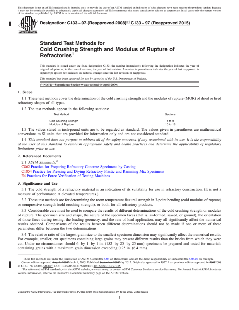
3.1 The cold strength of a refractory material is an indication of its suitability for use in refractory construction. (It is not a
measure of performance at elevated temperatures.)
3.2 These test methods are for determining the room temperature flexural strength in 3-point bending (cold modulus of rupture)
or compressive strength (cold crushing strength), or both, for all refractory products.
3.3 Considerable care must be used to compare the results of different determinations of the cold crushing strength or modulus
of rupture. The specimen size and shape, the nature of the specimen faces (that is, as-formed, sawed, or ground), the orientation
of those faces during testing, the loading geometry, and the rate of load application, may all significantly affect the numerical
results obtained. Comparisons of the results between different determinations should not be made if one or more of these
parameters differ between the two determinations.
3.4 The relative ratio of the largest grain size to the smallest specimen dimension may significantly affect the numerical results.
For example, smaller, cut specimens containing large grains may present different results than the bricks from which they were
cut. Under no circumstances should 6- by 1- by 1-in. (152- by 25- by 25-mm) specimens be prepared and tested for materials
containing grains with a maximum grain dimension exceeding 0.25 in. (6.4 mm).
These test methods are under the jurisdiction of ASTM Committee C08 on Refractories and are the direct responsibility of Subcommittee C08.01 on Strength.
Current edition approved Aug. 1, 2008March 1, 2015. Published September 2008May 2015. Originally approved in 1937. Last previous edition approved in 20032008
ε1
as C133 – 97 (2003).(2008) . DOI: 10.1520/C0133-97R08E01.10.1520/C0133-97R15.
For referenced ASTM standards, visit the ASTM website, www.astm.org, or contact ASTM Customer Service at service@astm.org. For Annual Book of ASTM Standards
volume information, refer to the standard’s Document Summary page on the ASTM website.
Copyright © ASTM International, 100 Barr Harbor Drive, PO Box C700, West Conshohocken, PA 19428-2959. United States
C133 − 97 (2015)
3.5 This test method is useful for research and development, engineering application and design, manufacturing process control,
and for developing purchasing specifications.
COLD CRUSHING STRENGTH
4. Apparatus
4.1 Testing Machine—Any form of standard mechanical or hydraulic compression testing machine conforming to the
requirements of Practices E4 may be used.
NOTE 1—For low-strength materials (such as insulating bricks or castables), a sensitivity of 20 lbf (67 kN) or less is required. The use of a hydraulic
testing machine is also preferred over the mechanical type for these materials.
4.2 Spherical Bearing Block—The plane surface of the spherical bearing block (see Fig. 1) shall have an area which is equal
to or greater than the cross section of the test specimen.
5. Test Specimens
3 3
5.1 Brick and Shapes (bulk density greater than 100 lb/ft (1.60 g/cm ))—The test specimens shall be 2-in. (51-mm) cubes or
cylinders, 2 in. (51 mm) in diameter by 2 in. (51 mm) high. The height should be parallel to the original direction of pressing of
the brick or shape. In the case of special shapes, only one specimen shall be cut from a single shape and as many of the original
surfaces as possible shall be preserved. In preparing specimens from irregular or large refractory shapes, any method involving the
use of abrasives, such as a high-speed abrasion wheel, core drill, or rubbing bed, that will produce a specimen with approximately
plane and parallel sides without weakening the structure of the specimen may be used.
3 3
5.2 Insulating Brick or Shapes (typical bulk density of 100 lb/ft (1.60 g/cm ), or greater than 45 % total porosity, or both)—The
1 1 1
test specimens shall be 4 ⁄2 by 4 ⁄2 by 2 ⁄2 or 3 in. (114 by 114 by 64 or 76 mm), each taken from a different brick. It is permissible
to prepare these specimens from the half-brick resulting from the modulus of rupture test (see Sections 9 – 14). The selected
compression test section shall be free of cracks, chipped surfaces, and other obvious defects. The test surfaces shall be
approximately parallel planes.
5.3 Castable Refractories—The test specimens shall be 2- by 2- by 2-in. (51- by 51- by 51-mm) cubes or cylinders 2 in. (51
mm) in diameter by 2 in. (51 mm) high, prepared by casting or gunning. It is permissible to prepare one specimen from each 9-
by 2- by 2-in. (230- by 51- by 51-mm) bar after the modulus of rupture test (see Sections 9 – 14). The selected compression test
section shall be free of cracks, chipped surfaces, and other obvious defects. The loaded surfaces shall be approximately parallel
planes. All samples must be dried at 220 to 230°F (105 to 110°C) for 18 h (overnight). Upon removal from the oven, allow the
sample to cool naturally until cool to the touch. Complete testing within 2 h of removal from the drying oven. (See Practices C862
and C1054.)
6. Procedure
6.1 At least five specimens from an equivalent number of refractory shapes compose a sample.
NOTE 2—For relatively weak specimens like insulating castables or insulating firebricks, a minimum sample size of ten specimens is preferred.
FIG. 1 Recommended Design for Crushing Test Assembly, Including Bearing Block
C133 − 97 (2015)
6.2 Brick and Shapes—Place a cellulose fiber wall board (for example, Masonite ) 0.25 in. (6.4 mm) in thickness and extending
0.5 in. (12.7 mm) or more beyond the edges of the loaded faces of the specimen. Apply the load parallel to the direction in which
the brick was originally pressed.
6.3 Regular and High Strength Castables—Place a cellulose fiber wall board 0.25 in. (6.4 mm) in thickness and extending 0.5
in. (12.7 mm) or more beyond the edges of the loaded faces of the specimen. Apply the load on the 2- by 2-in. (51- by 51-mm)
or 2-in. (51-mm) diameter face and perpendicular to the depth of the specimen as originally cast or gunned.
1 1
6.4 Insulating Brick or Shapes—Apply the load directly to the 4 ⁄2- by 4 ⁄2-in. (114- by 114-mm) surface of the test specimen.
3 3
6.5 Insulating Castables (typical bulk density of 100 lb/ft (1.60 g/cm ), or greater than 45 % total porosity, or both)—Apply
the load directly to the 2- by 2-in. (51- by 51-mm) face and perpendicular to the depth of the specimen as originally cast or gunned.
6.6 Use the bearing block on top of the test specimen, and position it so that the center of the sphere is in alignment with the
vertical axis of the specimen (see Fig. 1). Keep the spherical bearing block thoroughly lubricated to ensure accurate adjustment
which may be made by hand under a small initial load for each specimen.
NOTE 3—The spherical bearing block may not be necessary on test machines having mechanical linkages which ensure that the stress applied is colinear
with the axis of the specimen.
6.7 For dense refractories with sufficient strength to require greater than about 3 min per test, initial loading to one-half of the
anticipated failure load may be accomplished at any convenient rate exceeding the specified rate. Subsequently, each specimen
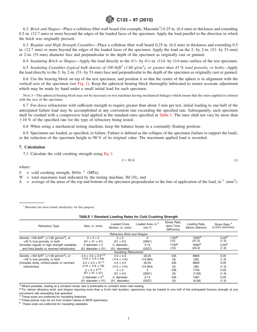
shall be crushed with a compressive load applied at the standard rates specified in Table 1. The rates shall not vary by more than
610 % of the specified rate for the type of refractory being tested.
6.8 When using a mechanical testing machine, keep the balance beam in a constantly floating position.
6.9 Specimens are loaded, as specified, to failure. Failure is defined as the collapse of the specimen (failure to support the load),
or the reduction of the specimen height to 90 % of its original value. The maximum applied load is recorded.
7. Calculation
7.1 Calculate the cold crushing strength using Eq 1:
S 5 W/A (1)
where:
S = cold crushing strength, lbf/in. (MPa),
W = total maximum load indicated by the testing machine, lbf (N), and
2 2
A = average of the areas of the top and bottom of the specimen perpendicular to the line of application of the load, in. (mm ).
Masonite has been found satisfactory for this purpose.
TABLE 1 Standard Loading Rates for Cold Crushing Strength
Stress Rate,
2 A
Loaded Cross Loaded Area, in. Loading Rate,
Strain Rate,
Refractory Type Size, in. (mm) lbf/in. /min
in./min (mm/min)
Section, in. (mm) mm ) lbf/min (kN/min)
(MPa/min)
Refractory Brick and Shapes
3 3 B B B
Density >100 lb/ft (>1.60 gm/cm ), or 2 × 2 × 2 2 × 2 4 1750 7000 0.05
(12) (31.2) (1.3)
<45 % true porosity, or both (51 × 51 × 51) (51 × 51) (2601)
B B B
(Includes regular or high strength castables 2 diameter × 2 2, diameter 3.14 1750 5500 0.05
(12) (24.3) (1.3)
and fired plastic or rammed refractories) (51 diameter × 51) (51, diameter) (2027)
Insulating Refractories
3 3 C,D
Density <100 lb/ft (<1.60 gm/cm ), or 4.5 × 4.5 × 2.5 4.5 × 4.5 20.25 435 8809 0.05
(114 × 114 × 64)
>45 % true porosity, or both (114 × 114) (13 064) (3) (39) (1.3)
C,D
(Includes dried, unfired plastic or rammed 4.5 × 4.5 × 3 4.5 × 4.5 20.25 435 8809 0.05
(114 × 114 × 76)
refractories) (114 × 114) (13 064) (3) (39) (1.3)
D,E
2 × 2 × 2 2 × 2 4 435 1740 0.05
(51 × 51 × 51)
(51 × 51) (2601) (3) (7.80) (1.3)
E
2 diameter × 2 2, diameter 3.14 435 1367 0.05
(51 diameter × 51) (51, diameter) (2027) (3) (6.08) (1.3)
A
Where possible, loading at a constant stress rate is preferable to constant strain rate loading.
B
For dense refractory brick and shapes requiring more than a 3-min test duration, specimens may be loaded to one half of the anticipated fracture strength at any
convenient rate exceeding that specified.
C
These sizes are preferred for insulating firebricks.
D
These pieces may be cut from broken halves of MOR specimens.
E
These sizes are preferred for insulating castables.
C133 − 97 (2015)
8. Report
8.1 Report the following:
8.1.1 Designation of the materials tested (that is, manufacturer, brand, description, lot number, etc.);
8.1.2 Specimen configuration, including size, shape, location in the original brick or shape, the character of the faces (that is,
cut, drilled, as-pressed, as-cast, etc.), and the specimen orientation during testing;
8.1.3 Pretreatment, if any, given to the test pieces (for example, curing, firing, coking, etc.);
8.1.4 Number of specimens in a sample;
8.1.5 Individual specimen dimensions, the maximum applied load, and the calculated cold crushing strength for each specimen
(see 7.1);
8.1.6 Mean cold crushing strength and standard deviation for each sample.
MODULUS OF RUPTURE
9. Apparatus
9.1 Testing Machine—Any form of standard mechanical or hydraulic compression testing machine conforming to the
requirements of Practices E4 may be used.
NOTE 4—Properly calibrated portable apparatus may be used.
5 1
9.2 Bearing Surfaces, that shall have a radius of curvature of ⁄8 in. (16 mm) or be cylindrical pieces 1 ⁄4-in. (32-mm) in
diameter. For 6- by 1- by 1-in. (152- by 25- by 25-mm) specimens, the radius of curvature shall be ⁄16 in. (5 mm) or cylindrical
pieces ⁄8 in. (10 mm) in diameter. All such bearing surfaces shall be straight and of a length at least equal to the width of the test
specimen. The supporting members for the lower bearing surfaces shall be constructed so as to provide a means for the alignment
of the bearing surfaces with the under surface of the test specimen because the test brick may have a longitudinal twist. Apparatus
of the design shown in Fig. 2 is recommended, although other types may be used, provided they conform to these requirements.
A satisfactory alternative design is shown in Fig. 3.
10. Test Specimens
3 3
10.1 Brick and Shapes (bulk density greater than 100 lb/ft (1.60 g/cm )—The preferred test specimens shall be standard 9- by
1 1
4 ⁄2- by 2 ⁄2- or 3-in. (228- by 114- by 64- or 76-mm) bricks, or specimens of equivalent size ground or cut from refractory shapes.
In the case of special shapes, only one specimen shall be cut from a single shape. As many original surfaces as possible shall be
preserved. Where brick sizes are impossible or impracticable, alternative specimen sizes of 9 by 2 by 2 in. (228 by 51 by 51 mm)
NOTE 1—The dimensions appearing in Fig. 2 are in inches. See table below for metric equivalents.
in. mm in. mm
3 1
⁄16 5 1 ⁄2 38
⁄4 6 2 51
⁄8 10 3 76
⁄2 13 4 102
5 1
⁄8 16 4 ⁄2 114
⁄4 19 5 127
1 25 7 178
1 ⁄4 32 12 305
FIG. 2 Recommended Design of Bearing Cylinders for Modulus of Rupture Test
C133 − 97 (2015)
NOTE 1—The dimensions appearing in Fig. 3 are in inches. See table included with Fig. 2 for metric equivalents.
FIG. 3 Al
...
Questions, Comments and Discussion
Ask us and Technical Secretary will try to provide an answer. You can facilitate discussion about the standard in here.