

FprEN 18328
(Main)Non-destructive testing - Thermographic testing - Active thermography with inductive excitation
- Abstract
This document specifies a method and establishes guidelines for non-destructive testing using active thermography with inductive excitation.
By using inductive heating of the test object, this active thermography method is suitable for inspecting test objects made of metals or other electrically conductive materials.
Such tests are conducted for:
- the detection of surface-breaking discontinuities, particularly cracks; and
- the detection of discontinuities located near the surface.
The functional principle of the defect detection can be based on a direct interaction of defect and excitation signal (defect selective) or an indirect interaction by using derivations of the applied heat flow.
For this purpose, active thermography with inductive excitation is conducted using different sources of excitation (inductors) in reflection and transmission configurations. Areas tested in one shot are typically between a few cm2 and a few hundred cm2, depending on the geometry of the used inductor. In dynamic configuration, larger areas can be tested.
Fields of application for active thermography with inductive excitation are to be found in industrial manufacturing and in maintenance (vehicle, drive system and power plant components, jointing technique, semi-finished products, etc.).
Active thermography with inductive excitation is also called inductive thermography or eddy-current excited thermography.
- Status
- Not Published
- Publication Date
- 17-Mar-2027
- Technical Committee
- CEN/TC 138 - Non-destructive testing
- Drafting Committee
- CEN/TC 138/WG 11 - Infrared thermographic testing

FprEN 18328 is a draft European Standard from CEN for non-destructive testing (NDT) by active thermography with inductive excitation. It specifies how to inspect metals and other electrically conductive materials for surface-breaking discontinuities, especially cracks, and for near-surface discontinuities. The document is written for testing personnel, inspectors, and technical staff who need to set up the method, judge its suitability, and document the results.
What does FprEN 18328 specify?
FprEN 18328 specifies a method and gives guidance for active thermography with inductive excitation. It covers both the inspection principle and the practical setup for conductive test objects, including metals.
The scope links the method to two main detection tasks - surface-breaking discontinuities and discontinuities close to the surface. It also notes that the method can work through direct defect interaction with the excitation signal or through thermal effects caused by the induced heat flow.
The document is organized into nine clauses and two informative annexes.
| Annex | What it covers |
|---|---|
| Annex A | Influential parameters to consider when qualifying the NDT system for active thermography with inductive excitation |
| Annex B | Example reference test specimens |
The main clauses cover scope, normative references, terms and definitions, personnel qualification, the principles and equipment setup, reference test specimens, test procedure, evaluation and classification, and the test report. In practice, that means the document does not stop at the physics of the method - it also tells the user how to prepare, run, assess, and record a test.
What are the key requirements of FprEN 18328?
FprEN 18328 sets requirements and guidance for planning, running, and documenting active thermography with inductive excitation. The most important points are the qualification of personnel, the choice of excitation and equipment, the handling of the test object, and the reporting of results.
Personnel and test planning
Clause 4 requires qualification records in accordance with EN ISO 9712 or an equivalent system. Testing personnel also need knowledge of the test objects, the manufacturing process where relevant, and the defects that are expected. In practice, the operator must understand both the part and the inspection method well enough to choose a suitable setup and interpret the indications.
Clause 7 requires a test instruction, and that instruction has to state the indication-recording and acceptance criteria. The method also has to be validated for the testing task, with influential parameters considered as described in Annex A. That matters because sensitivity depends on material, geometry, defect type, and inspection conditions.
Excitation, equipment, and viewing
Clauses 5.1 to 5.4 require an induction generator, an inductor, an IR camera, and sometimes a control unit for synchronization. The document covers pulse or step excitation, periodic excitation, and dynamic testing with relative movement, in both reflection and transmission configurations. This gives the reader the main ways the method can be applied to different parts and inspection situations.
Clause 5.3 explains that induction frequency controls the electromagnetic penetration depth, or skin depth. Higher frequency reduces penetration, while lower frequency increases it, so the frequency must match the expected defect depth and the material. In practice, this is one of the main choices that determines whether the method can see only very shallow defects or deeper subsurface ones.
Clause 5.4 requires the inductor to suit the geometry of the test object and the orientation of the discontinuity, and it must not block the IR camera view. If the area cannot be fully excited in one shot, it can be divided into sub-areas, and for crack detection the inductor may need to be repositioned to excite roughly perpendicular directions. This is what makes coverage and defect orientation control part of the setup, not just the data analysis.
Clause 5.5 sets performance expectations for the IR camera: spectral range, temperature range, resolution, stability, detector format, optics, spatial resolution, temporal resolution, frame rate stability, integration mode, and synchronization. The practical point is that the camera must be able to resolve the thermal contrast created by the excitation and sample it fast enough for the chosen test mode.
Clause 5.6 and 5.7 deal with electromagnetic compatibility and positioning. The setup should limit image artifacts from electromagnetic fields, and the test object should be positioned reproducibly with suitable holding or motion equipment. This helps avoid false indications caused by reflections, vibration, or electrical interference.
Procedure, safety, and records
Clause 5.8 requires safety measures for strong electromagnetic fields, electrical hazards, excessive heating, fire, burns, cooling failure, and emergency shutdown. Operators and nearby persons have to be protected, so the inspection procedure must include safety control, not only measurement steps.
Clauses 6, 7, 8, and 9 require reference test specimens, surface preparation, data evaluation, classification, and reporting. The document also notes that temperature calibration is not needed for every application, but where temperature measurement is used it has to follow the camera manufacturer’s recommendations and be checked against EN 16714-1. In practice, the inspection team must show how the setup was checked, how the surface was prepared, how the images were processed, and how the indications were judged.
What terms does FprEN 18328 define?
FprEN 18328 defines key terms that control how the method is set up and interpreted.
- Electric decay time - the time from switching off the inductor until the current has fallen to 36.8% of its initial value.
- Electric settling time - the time from switching on the inductor until the current has reached 63.2% of its set value.
- Skin depth - the penetration depth at which the magnetic field strength has fallen to 36.8% of the surface value.
- Electromagnetic thickness - the thickness of the test object expressed in skin depths; the document treats a part as electromagnetically thick when its thickness is more than twice the skin depth.
- Induction frequency - the frequency of the alternating current supplied by the induction generator to the inductor.
- Induction generator - the equipment that produces the alternating current with the required power and time profile for the inductor.
- Inductor - the electromagnetic element that creates the changing magnetic field and the induced eddy currents in the test object.
- Lift-off distance - the distance between the inductor and the surface of the test object.
Who uses FprEN 18328?
FprEN 18328 is intended for people who perform or specify NDT with thermography on electrically conductive parts. That includes inspection personnel, NDT coordinators, quality teams, and engineers who need to choose an inspection setup or judge whether the method fits the defect size, depth, and material.
The document points to industrial manufacturing and maintenance as the main application areas. Examples named in the scope include vehicle components, drive system and power plant components, joining technique, and semi-finished products. In practice, users apply it to crack detection, near-surface defect detection, procedure validation, and the preparation of test instructions and reports.
Which standards are used with FprEN 18328?
FprEN 18328 uses several related standards that support the method and its documentation.
- EN 16714-1 - provides the general principles for thermographic testing and is also used for system testing and calibration checks.
- EN 16714-2 - covers thermographic testing equipment and supports the camera-related requirements.
- EN 16714-3 - gives the terms and definitions used for thermographic testing.
- EN 17119 - provides the wider active thermography framework, including test configurations and image-sequence processing.
- EN ISO 9712 - sets the qualification and certification basis for NDT personnel.
What does the FprEN 18328 document contain?
FprEN 18328 contains the method description, the main setup principles, and the practical controls needed to run inductive thermography. It includes figures for the basic system arrangement, excitation configurations, coil shapes, and magnetic field behavior, plus formulas that show how frequency affects skin depth and heating.
Table 1 sets the minimum camera-related features to consider, and Annex A lists influential parameters for validation and qualification of the NDT system. Annex B gives example reference test specimens for different notch depths, lengths, angles, spacing, and subsurface coverage, which are useful for procedure development and method validation.
The document also includes the test procedure, evaluation and classification rules, and the minimum report content. For a user, that means the standard is not only about the physics of inductive thermography - it also supports setup selection, reference-piece selection, indication assessment, and formal reporting.
Get Certified
Connect with accredited certification bodies for this standard

IMP NDT d.o.o.
Non-destructive testing services. Radiography, ultrasonic, magnetic particle, penetrant, visual inspection.
Inštitut za kovinske materiale in tehnologije
Institute of Metals and Technology. Materials testing, metallurgical analysis, NDT.
Q Techna d.o.o.
NDT and quality assurance specialist. 30+ years experience. NDT personnel certification per ISO 9712, nuclear and thermal power plant inspections, QA/
Sponsored listings
Frequently Asked Questions
FprEN 18328 is a draft published by the European Committee for Standardization (CEN). Its full title is "Non-destructive testing - Thermographic testing - Active thermography with inductive excitation". This standard covers: This document specifies a method and establishes guidelines for non-destructive testing using active thermography with inductive excitation. By using inductive heating of the test object, this active thermography method is suitable for inspecting test objects made of metals or other electrically conductive materials. Such tests are conducted for: - the detection of surface-breaking discontinuities, particularly cracks; and - the detection of discontinuities located near the surface. The functional principle of the defect detection can be based on a direct interaction of defect and excitation signal (defect selective) or an indirect interaction by using derivations of the applied heat flow. For this purpose, active thermography with inductive excitation is conducted using different sources of excitation (inductors) in reflection and transmission configurations. Areas tested in one shot are typically between a few cm2 and a few hundred cm2, depending on the geometry of the used inductor. In dynamic configuration, larger areas can be tested. Fields of application for active thermography with inductive excitation are to be found in industrial manufacturing and in maintenance (vehicle, drive system and power plant components, jointing technique, semi-finished products, etc.). Active thermography with inductive excitation is also called inductive thermography or eddy-current excited thermography.
This document specifies a method and establishes guidelines for non-destructive testing using active thermography with inductive excitation. By using inductive heating of the test object, this active thermography method is suitable for inspecting test objects made of metals or other electrically conductive materials. Such tests are conducted for: - the detection of surface-breaking discontinuities, particularly cracks; and - the detection of discontinuities located near the surface. The functional principle of the defect detection can be based on a direct interaction of defect and excitation signal (defect selective) or an indirect interaction by using derivations of the applied heat flow. For this purpose, active thermography with inductive excitation is conducted using different sources of excitation (inductors) in reflection and transmission configurations. Areas tested in one shot are typically between a few cm2 and a few hundred cm2, depending on the geometry of the used inductor. In dynamic configuration, larger areas can be tested. Fields of application for active thermography with inductive excitation are to be found in industrial manufacturing and in maintenance (vehicle, drive system and power plant components, jointing technique, semi-finished products, etc.). Active thermography with inductive excitation is also called inductive thermography or eddy-current excited thermography.
FprEN 18328 is classified under the following ICS (International Classification for Standards) categories: 19.100 - Non-destructive testing. The ICS classification helps identify the subject area and facilitates finding related standards.
FprEN 18328 is available in PDF format for immediate download after purchase. The document can be added to your cart and obtained through the secure checkout process. Digital delivery ensures instant access to the complete standard document.
Standards Content (Sample)
SLOVENSKI STANDARD
01-marec-2026
Neporušitvene preiskave - Termografsko preiskave - Aktivna termografija z
induktivnim vzbujanjem
Non-destructive testing - Thermographic testing - Active thermography with inductive
excitation
Zerstörungsfreie Prüfung - Thermografische Prüfung - Aktive Thermografie mit induktiver
Anregung
Essais non destructifs - Analyses thermographiques - Thermographie excitée par
induction
Ta slovenski standard je istoveten z: prEN 18328
ICS:
19.100 Neporušitveno preskušanje Non-destructive testing
2003-01.Slovenski inštitut za standardizacijo. Razmnoževanje celote ali delov tega standarda ni dovoljeno.
DRAFT
EUROPEAN STANDARD
prEN 18328
NORME EUROPÉENNE
EUROPÄISCHE NORM
March 2026
ICS 19.100
English Version
Non-destructive testing - Thermographic testing - Active
thermography with inductive excitation
Essais non destructifs - Analyses thermographiques - Zerstörungsfreie Prüfung - Thermografische Prüfung -
Thermographie excitée par induction Aktive Thermografie mit induktiver Anregung
This draft European Standard is submitted to CEN members for enquiry. It has been drawn up by the Technical Committee
CEN/TC 138.
If this draft becomes a European Standard, CEN members are bound to comply with the CEN/CENELEC Internal Regulations
which stipulate the conditions for giving this European Standard the status of a national standard without any alteration.
This draft European Standard was established by CEN in three official versions (English, French, German). A version in any other
language made by translation under the responsibility of a CEN member into its own language and notified to the CEN-CENELEC
Management Centre has the same status as the official versions.
CEN members are the national standards bodies of Austria, Belgium, Bulgaria, Croatia, Cyprus, Czech Republic, Denmark, Estonia,
Finland, France, Germany, Greece, Hungary, Iceland, Ireland, Italy, Latvia, Lithuania, Luxembourg, Malta, Netherlands, Norway,
Poland, Portugal, Republic of North Macedonia, Romania, Serbia, Slovakia, Slovenia, Spain, Sweden, Switzerland, Türkiye and
United Kingdom.
Recipients of this draft are invited to submit, with their comments, notification of any relevant patent rights of which they are
aware and to provide supporting documentation.
Warning : This document is not a European Standard. It is distributed for review and comments. It is subject to change without
notice and shall not be referred to as a European Standard.
EUROPEAN COMMITTEE FOR STANDARDIZATION
COMITÉ EUROPÉEN DE NORMALISATION
EUROPÄISCHES KOMITEE FÜR NORMUNG
CEN-CENELEC Management Centre: Rue de la Science 23, B-1040 Brussels
© 2026 CEN All rights of exploitation in any form and by any means reserved Ref. No. prEN 18328:2026 E
worldwide for CEN national Members.
prEN 18328:2026 (E)
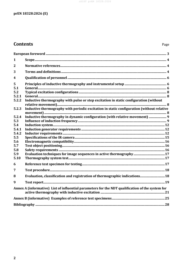
Contents Page
European foreword . 3
1 Scope . 4
2 Normative references . 4
3 Terms and definitions . 4
4 Qualification of personnel . 6
5 Principles of inductive thermography and instrumental setup . 6
5.1 General. 6
5.2 Typical excitation configurations . 8
5.2.1 General. 8
5.2.2 Inductive thermography with pulse or step excitation in static configuration (without
relative movement). 8
5.2.3 Inductive thermography with periodic excitation in static configuration (without relative
movement) . 8
5.2.4 Inductive thermography in dynamic configuration (with relative movement) . 9
5.3 Influence of induction frequency . 9
5.4 Induction system . 12
5.4.1 Induction generator requirements . 12
5.4.2 Inductor requirements . 12
5.5 Specifications of the IR camera . 15
5.6 Electromagnetic compatibility . 16
5.7 Test object positioning. 16
5.8 Safety requirements . 16
5.9 Evaluation techniques for image sequences in active thermography . 17
5.10 Thermography system test. 17
6 Reference test specimen for testing . 17
7 Test procedure . 18
8 Evaluation, classification and registration of thermographic indications. 18
9 Test report . 19
Annex A (informative) List of influential parameters for the NDT qualification of the system for
active thermography with inductive excitation . 21
Annex B (informative) Examples of reference test specimens . 25
Bibliography . 28
prEN 18328:2026 (E)
European foreword
This document (prEN 18328:2026) has been prepared by Technical Committee CEN/TC 138 “Non-
destructive testing”, the secretariat of which is held by AFNOR.
This document is currently submitted to the CEN Enquiry.
prEN 18328:2026 (E)
1 Scope
This document specifies a method and establishes guidelines for non-destructive testing using active
thermography with inductive excitation.
By using inductive heating of the test object, this active thermography method is suitable for inspecting
test objects made of metals or other electrically conductive materials.
Such tests are conducted for:
— the detection of surface-breaking discontinuities, particularly cracks; and
— the detection of discontinuities located near the surface.
The functional principle of the defect detection can be based on a direct interaction of defect and
excitation signal (defect selective) or an indirect interaction by using derivations of the applied heat flow.
For this purpose, active thermography with inductive excitation is conducted using different sources of
excitation (inductors) in reflection and transmission configurations. Areas tested in one shot are typically
2 2
between a few cm and a few hundred cm , depending on the geometry of the used inductor. In dynamic
configuration, larger areas can be tested.
Fields of application for active thermography with inductive excitation are to be found in industrial
manufacturing and in maintenance (vehicle, drive system and power plant components, jointing
technique, semi-finished products, etc.).
Active thermography with inductive excitation is also called inductive thermography or eddy-current
excited thermography.
2 Normative references
The following documents are referred to in the text in such a way that some or all of their content
constitutes requirements of this document. For dated references, only the edition cited applies. For
undated references, the latest edition of the referenced document (including any amendments) applies.
EN 16714-1, Non-destructive testing — Thermographic testing — Part 1: General principles
EN 16714-2, Non-destructive testing — Thermographic testing — Part 2: Equipment
EN 16714-3, Non-destructive testing — Thermographic testing — Part 3: Terms and definitions
EN 17119, Non-destructive testing — Thermographic testing — Active thermography
EN ISO 9712, Non-destructive testing — Qualification and certification of NDT personnel (ISO 9712)
3 Terms and definitions
For the purposes of this document, the terms and definitions given in EN 16714-3 and EN 17119 and the
following apply.
ISO and IEC maintain terminology databases for use in standardization at the following addresses:
— ISO Online browsing platform: available at https://www.iso.org/obp/
— IEC Electropedia: available at https://www.electropedia.org/
prEN 18328:2026 (E)
3.1
electric decay time
t
a
time interval between the instant of disconnection and the instant when
−1
the inductor current has decayed to 36,8 % (e ) of its initial value
3.2
electric settling time
t
e
time interval between the instant of connection and the instant when the inductor current reaches a value
−1
of 63,2 % (1-e ) of its set value
3.3
skin depth
penetration depth
δ
penetration depth of the electromagnetic field into the test object at which the magnetic field strength
−1
drops to a value of 36,8 % (e ) of the surface value
3.4
electromagnetic thickness
geometrical thickness in units of skin depth
Note 1 to entry: A test object is deemed electromagnetically thick if its geometrical thickness exceeds twice the skin
depth, otherwise, the test object is deemed electromagnetically thin.
3.5
induction frequency
frequency of the alternating current supplied by the induction generator to the connected inductor
3.6
induction generator
equipment generating an alternating current of sufficient power and with an adjustable time profile for
operating the inductor
3.7
inductor
electromagnetic element supplying alternating current to generate a temporally variable magnetic field
and thereby a temporally variable eddy current in the test object
3.8
lift-off distance
distance between the inductor and the surface of the test object
3.9
coverage
ligament
remaining thickness wall
thickness of the material that lies between the surface under consideration and a discontinuity located
below this surface, which corresponds to the depth location of the discontinuity
prEN 18328:2026 (E)
4 Qualification of personnel
Knowledge and skills regarding active thermography with inductive excitation shall be demonstrated by
qualification. Proof shall be provided in the form of qualification records in accordance with EN ISO 9712
or equivalent. Testing personnel shall have sufficient knowledge regarding the test objects,
manufacturing processes, if applicable, and any potential defects to be detected.
5 Principles of inductive thermography and instrumental setup
5.1 General
Inductive thermography is a technique of active thermography which can be applied to electrically
conductive test objects. With this technique, an inductor is used to generate a current in the test object.
The minimum equipment required to perform inductive thermography includes an induction generator,
an inductor, an infrared camera and eventually a control unit for temporal synchronization of the
excitation source and image recording. A basic instrumental setup is given in Figure 1.
Key
1 test object
2 induction generator
3 IR camera
4 discontinuity
5 IR radiation
6 inductor
7 control unit
Figure 1 — Schematic illustration of inductive thermography
Inductive thermography allows for the inspection of a global surface up to a few hundred cm with a short
excitation duration (around 100 ms). It can be considered as an alternative to either magnetic particle
testing or dye penetrant testing due to equivalent quality detection obtained on linear discontinuities.
Advantages compared to these two methods are the absence of chemical products, and the possibility of
automatable non-contact inspections.
Different mechanisms can be used to detect defects depending on their orientation and depth.
The main physical mechanism of inductive thermography is due to the electromagnetic interaction
between induced currents and a surface or subsurface discontinuity to be detected. A discontinuity can
change the propagation of the induced currents and generate regions of increased or decreased current
density. The temperature differences thus obtained can be viewed on the surface of the test specimen
with an infrared camera. This mechanism can detect a surface breaking discontinuity and subsurface
prEN 18328:2026 (E)
discontinuity only if its coverage is less than half of the skin depth (see 5.3). In some cases, the detection
of the discontinuity can be improved by combination of this electromagnetic interaction with a thermal
interaction. Indeed, the orientation of the discontinuity in relation to the surface obstructs the thermal
distribution and leads to a decrease in local heat dissipation.
Another physical mechanism occurs that can be used to detect deeper subsurface discontinuities. The
ohmic losses of the eddy currents cause transient heat fluxes in the test object which thermally interact
with defects even beyond the skin depth. The resulting contrasts are detected by the IR camera.
Typical cases of linear discontinuities and associated detection mechanisms using inductive
thermography are shown in Figure 2. The dark zone shown in the cross section of the test object indicates
the skin depth.
The vertical surface-breaking discontinuity shown in Figure 2 a) can be detected via the disturbance of
induced currents and the change in heat generation. The vertical subsurface discontinuity with its upper
end located within half of the skin depth shown in Figure 2 b) can be detected analogous to the surface-
breaking discontinuity shown in Figure 2 a).
The inclined discontinuity shown in Figure 2 c) is easier to detect than in cases 2 a) and 2 b) since, in
addition to the change in heat generation, the quantity of heat released in the wedge between
discontinuity and surface is less easily dissipated due to the limited heat conduction into the bulk
material. The orientation of the inclination could thus become visible in the thermogram.
The discontinuity parallel to the surface shown in Figure 2 d) can be detected thermally as the heat
release is greater above than below the discontinuity and the heat quantity above the discontinuity can
only be dissipated at a smaller rate compared to the defect-free material. The discontinuity parallel to the
surface shown in Figure 2 e) can be detected via its interaction with the heat flux from the surface into
the depth. Such discontinuity obstructs only the thermal distribution, not the induced currents. In this
case, the measurement time needs to be increased until the discontinuity can be detected by thermal
contrast.
The subsurface discontinuity shown in Figure 2 f) can be detected by neither electromagnetic nor thermal
interactions. It may be detected, however, by sufficiently increasing the skin depth by reducing the
induction frequency (see 5.3).
a) b) c)
d) e) f)
Figure 2 — Types of linear discontinuity in inductive thermography
prEN 18328:2026 (E)
In inductive thermography, the signal depends on the discontinuity depth/coverage. This particularly
applies in those cases shown in Figure 2 a) and Figure 2 c). For constant discontinuity dimensions (width
and length), this correlation will, upon a corresponding calibration, facilitate an estimation of the
discontinuity depth for both vertical and inclined discontinuities [1].
5.2 Typical excitation configurations
5.2.1 General
According to EN 17119, inductive thermography can be performed in static as well as in dynamic
configuration and with different types of temporal excitation.
Reflection configuration is usually used in inductive thermography, but transmission configuration can
also be used under certain conditions.
5.2.2 Inductive thermography with pulse or step excitation in static configuration (without
relative movement)
In this configuration, an inductive excitation with the temporal form of a pulse (see Figure 3) or a step is
applied from the induction generator. The lower limit of excitation duration is determined by the electric
response times, i.e. settling and decay times, and also by the available maximum power of the generator.
The excitation duration influences the discontinuity detection capability.
Key
t time
A amplitude of temperature or excitation current
1 temperature
2 excitation current
Figure 3 — Evolution of the temperature during pulse excitation
5.2.3 Inductive thermography with periodic excitation in static configuration (without relative
movement)
In this configuration, the induction generator is amplitude-modulated using a modulation frequency
significantly smaller than the induction frequency. In an ideal case, the excitation of the discharged power
shows a sinusoidal shape. Usually, square modulation is applied for which a duty cycle of 1:1 has proven
efficient.
NOTE Here, periodic excitation is synonymous for multi pulse excitation.
prEN 18328:2026 (E)
5.2.4 Inductive thermography in dynamic configuration (with relative movement)
In this configuration, inductive thermography is performed with relative movement between the test
object and a set composed of inductor and IR camera. Inductor and IR camera shall be attached to each
other at a given distance. The test object moves at a defined speed relative to the inductor or vice versa.
Excitation is continuously switched on, usually at a set induction frequency. This configuration is
approximately equivalent to a pulse or step excitation mode configuration if the relative speed is
constant. For further details, refer to DIN 54187 [2].
5.3 Influence of induction frequency
The induction frequency determines the electromagnetic penetration depth δ, also called
electromagnetic skin depth. It is given by:
δ= (1)
πσµ µ f
0 r ind
where
-1
σ is the electrical conductivity (S.m );
-2
µ
0 is the permeability constant (N.A );
µ
r is the effective relative permeability at induction frequency f ;
ind
f is the induction frequency (Hz).
ind
As the induction frequency increases, the skin depth decreases. The skin depth is also strongly influenced
by the relative permeability of the material µ . The skin depth is approximately 50 µm in case of ferritic
r
steel at an induction frequency f = 100 kHz and approximately 1,4 mm in case of austenitic steel at the
ind
same induction frequency, see Figure 4.
prEN 18328:2026 (E)
Key
induction frequency in kHz
f
ind
δ skin depth in mm
1 carbon fibre reinforced polymer
2 titanium alloy
3 austenitic steel
4 aluminium alloy
5 copper alloy
6 ferritic steel
Figure 4 — Skin depth as a function of the induction frequency for various materials
Figure 5 shows the classification of electrically conductive materials in four groups according to the skin
depth of induced current at 100 kHz and their thermal diffusion length after 100 ms excitation. Group 1
includes ferromagnetic metals, group 2 includes non-ferromagnetic metals with high electrical
conductivity, group 3 includes non-ferromagnetic metals with lower electrical conductivity and group 4
includes non-metallic materials. The relation between the skin depth and the thermal diffusion length
has an influence on the detectability of the discontinuities shown in Figure 2.
prEN 18328:2026 (E)
Key
X electromagnetic skin depth for 100 kHz, in mm
Y thermal diffusion length for t=100 ms, in mm
1 ferromagnetic material/ moderate electrical conductivity / moderate thermal diffusivity
2 non-ferromagnetic material / high electrical conductivity / high thermal diffusivity
3 non-ferromagnetic material / moderate electrical conductivity / moderate thermal diffusivity
4 non-metallic material / low electrical conductivity / moderate thermal diffusivity
Figure 5 — Classification of electrically conductive materials according to the skin depth and
their thermal diffusion length
The induction frequency also influences the generated heat. The heat density q released on a flat
electromagnetically thick surface is approximately given by:
πµ µ
b
0r
qf= (2)
ind
σ
2µ
e
where
b is the amplitude of the alternating magnetic field on the surface of the test object (T);
-2).
q is the heat density (W.m
for further symbols, see Formula (1).
Formula (2) shows that, for a given magnetic field amplitude, the heating power increases with the square
root of the induction frequency.
NOTE Formula (2) describes alternating field effects for small amplitudes only. It is known that, e.g. in
ferromagnetic materials, static magnetic fields superimposing the high-frequency alternating field can influence the
released thermal power [3].
prEN 18328:2026 (E)
The induced current causes heating in proportion to the square value of the local current density.
5.4 Induction system
5.4.1 Induction generator requirements
The induction generator shall have a sufficiently high power for pulse excitation. Different generator
technologies with and without resonance circuit are available and can be applied. Typical pulse or step
durations range from few tens of milliseconds up to a few seconds to be adapted to the depth of the
discontinuity. For generating short pulses, the electrical settling and decay times of the generator shall
be as short as possible.
It shall be possible to modulate the amplitude of induction generators intended for sinusoidal excitation.
For this mode of excitation and for testing with relative movement, the generator shall be suitable to be
continuously switched on.
Particular attention for pulse or periodic excitation shall be put in the synchronization between the heat
generation and the thermal sequence to be analysed.
An induction generator can be externally controlled and synchronized. As an alternative when testing
with a continuous test object, the adjustable power is supplied as alternating current in a free-running
mode.
In case of resonant circuit induction generators, the inductor is part of the electric resonant circuit. The
frequency of the generator shall be manually or automatically set to a steady value of the resonance
frequency. The exact resonance frequency may vary subject to the geometry, the lift-off distance and the
material of the test object.
5.4.2 Inductor requirements
5.4.2.1 General
Inductors are selected according to the test object geometry to be tested and discontinuities to be
detected. As selection criteria, the local distribution of eddy-current or temperature can be used.
Therefore, the size, the position on the test object and the orientation of the discontinuities to be detected
shall be considered.
The inductor shall not cover the area to be within the field of view and inspected with the IR camera. It
shall be ensured, that the entire defined test area is sufficiently excited by the inductor. If this is not
possible, the test area can be divided into sub areas which are tested one after each other. Additionally,
the direct interaction of the eddy-current with the surface and surface near discontinuities shall be
ensured, as shown in Figure 2 a) to d). For the purpose of crack detection, if the discontinuity orientation
is unknown, the inductor may be repositioned, or other suitable measures may be applied to ensure eddy-
current orientation in at least two roughly perpendicular directions of the test area.
In case of long excitation or repeated excitation, cooling of the inductors may be required. For this
purpose, inductors which are cooled by water or air flow are generally used.
Transient thermal radiation from the inductor, which is caused by the heating of the inductor itself should
be avoided as far as possible. This thermal radiation can be reflected from the test object surface and so
influencing the postprocessing and the results. For this purpose, anti-reflectance coatings can be applied
using materials of low thermal conductivity. Reflections should also be avoided (e.g. when using copper
coils).
Inductors can be open air-cored coils or coils with magnetic cores. Some typical inductor shapes are
shown below and are detailed in 5.4.2.2 to 5.4.2.8.
prEN 18328:2026 (E)
a) round coil b) pancake coil c) linear coil
d) double-D coil e) Helmholtz coil f) double solenoid coil
Figure 6 — Typical inductor shapes
Figure 6 shows schematically the placement of the coils relatively to the test object and the orientation
of eddy-currents. The resulting eddy-currents, which are usually exploited for thermographic testing, are
illustrated by arrows.
5.4.2.2 Round or square coils and shape-adapted coils
A coil with one or more turns is positioned in parallel to the surface of the test object (see Figure 6 a)).
The eddy currents are concentrated close to the coil and decrease as one gets closer to the centre of the
coil. In the centre, the eddy current equal zero.
Round or square coils are also used as concentric coils for the testing of rod material.
Additionally, shape-adapted concentric coils are used allowing the excitation to be as constant as
possible.
5.4.2.3 Pancake coils
A spiral shaped coil is positioned in parallel to the surface
...