

prEN 13397
(Main)Industrial valves - Metallic diaphragm valves
- Abstract
This document specifies minimum requirements applicable to design, final assessment, designation, marking and documentation for diaphragm valves:
- having unlined and lined metallic bodies;
- having weir, weirless and straight-through body designs;
- for operation with manual handwheel or actuator;
- for use with flanged, welded and threaded pipe end connections;
- used for isolating, regulating or controlling applications or any combination thereof.
The PN and Class ranges are:
- PN 6, PN 10, PN 16 and PN 25;
- Class 125 and Class 150.
The size range is:
- for flanged valves: sizes DN 15, DN 20, DN 25, DN 32, DN 40, DN 50, DN 65, DN 80, DN 100, DN 125, DN 150, DN 200, DN 250, DN 300, DN 350, DN 400, DN 450 and DN 500;
- for screwed valves: sizes NPS ¼, ⅜, ½, ¾, 1, 1¼, 1½, 2, 2½ and 3;
- for weld end valves: sizes DN 8, DN 10, DN 15, DN 20, DN 25, DN 32, DN 40, DN 50, DN 65, DN 80, DN 100, DN 125, DN 150 and DN 200.
NOTE 1 Sizes are listed in Table D.1.
This document applies to metallic diaphragm valves used for all industrial applications.
For applications in accordance with the European legislation for pressure equipment, EN 16668:2025 applies together with this document.
Additional requirements given in the relevant application standards can apply to diaphragm valves used for more specific applications (e.g. for the water industry, the chemical and petrochemical process industry).
For chemical and petrochemical applications, EN 12569:2020 apply together with this document.
For water supply applications, EN 1074-1:2000 and EN 1074-2:2000 apply together with this document.
NOTE 2 National potable water approval schemes (WRAS, DVGW, ACS, etc.) can apply in addition to the valve design standards.
For process control applications, EN 1349:2009 and EN 60534-2-1:2011 apply together with this document.
For cryogenic applications, EN 1626:2008 apply together with this document.
For fire-safe applications, EN ISO 10497:2022 apply together with this document.
For fugitive emissions applications, EN ISO 15848-1:2015+A1:2017 and EN ISO 15848-2:2015 apply together with this document.
Other specific application standards, regulatory requirements, purchaser specifications or national approval schemes can also exist and can apply depending on the intended service, installation location, fluid, pressure/temperature conditions and end-use application.
The correspondence between DN and NPS is given for information in Annex C.
- Status
- Not Published
- Publication Date
- 31-May-2026
- Technical Committee
- CEN/TC 69 - Industrial valves
- Drafting Committee
- CEN/TC 69/WG 15 - Diaphragm valves
- Current Stage
- 4020 - Submission to enquiry - Enquiry
- Start Date
- 22-Oct-2026
- Due Date
- 15-May-2024
- Completion Date
- 22-Oct-2026

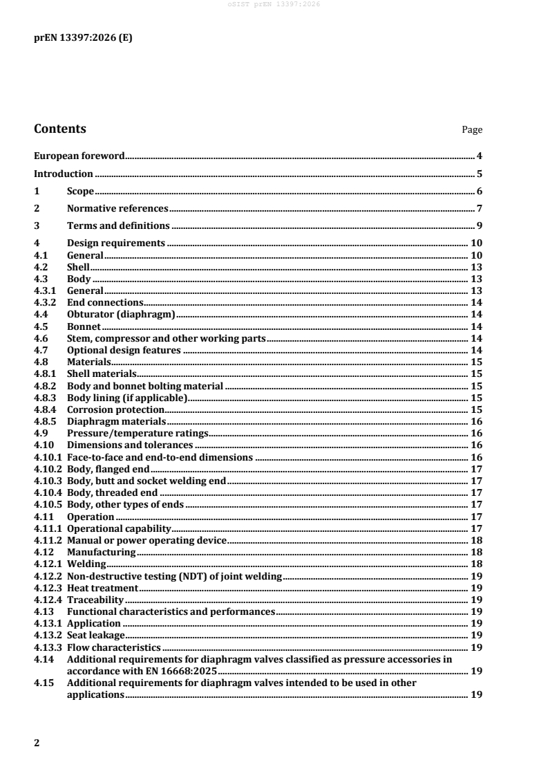
prEN 13397 is a CEN draft European Standard for industrial valves - metallic diaphragm valves. It specifies minimum requirements for the design, final assessment, designation, marking and documentation of diaphragm valves for industrial use, including valves with metallic bodies, manual handwheel or actuator operation, and flanged, welded or threaded connections.
What does prEN 13397 specify?
prEN 13397 sets the minimum requirements for metallic diaphragm valves used in industrial applications, including isolating, regulating and controlling service. It covers unlined and lined metallic bodies, weir, weirless and straight-through body designs, and valves with manual or power operation.
The document is organized into scope, normative references, terms and definitions, design requirements, final assessment, designation, marking, storage and transportation, and documentation. It also includes informative annexes for specification data, corrosion protection, DN/NPS correspondence, and the relationship with EN 16668:2025 and the Pressure Equipment Directive.
| Annex | What it covers |
|---|---|
| Annex A | Valve data sheet template for specifying a diaphragm valve |
| Annex B | Environmental corrosion protection and corrosion categories |
| Annex C | Correspondence between DN and NPS |
| Annex D | Relationship with EN 16668:2025 |
| Annex ZA | Relationship with Directive 2014/68/EU |
The scope also ties the standard to other application standards where needed, for example for water supply, chemical and petrochemical service, process control, cryogenic service, fire-safe service, and fugitive emissions. In practice, this means a buyer often needs prEN 13397 together with a service-specific standard, not as a stand-alone document.
What are the key requirements of prEN 13397?
Design basis, shell and materials
prEN 13397 requires the valve design to be agreed, and recommends using the valve data sheet in Annex A for that purpose. Clause 4.1 also states that the valve shall be either weir type or straight-through type, and that the document does not prescribe every design detail.
Shell strength is handled differently depending on whether the valve is within the scope of European pressure equipment legislation. Clause 4.2 points to EN 16668:2025 for pressure equipment applications, and to EN 12516-1, EN 12516-2, EN 12516-3 or EN 12516-4 for other applications. For a designer, this means the shell sizing method has to match the intended legal and technical context.
Material selection is tied to service conditions, including media, temperature and pressure. Clause 4.8 requires shell, bolting, lining and diaphragm materials to be chosen for the intended use, with the relevant material type identified in the technical documentation.
Body, end connections and pressure ratings
Clause 4.3 allows straight, angle or oblique body patterns and both lined and unlined bodies. It also covers flanged, butt-welding, mechanical, threaded and hygienic clamp end connections. If end-of-line service is limited, that limitation has to be identified, because it affects safe installation and use.
Clause 4.9 links pressure/temperature ratings to the body material group and the applicable flange standard. When the valve has pressure or temperature limits caused by materials or design, those limits have to be marked and included in the designation. In practice, the purchaser needs these limits before selecting the valve for a system.
Operation and functional performance
Clause 4.11 requires every diaphragm valve to be operable from fully closed to fully open, and back again, at a differential pressure equal to PS at 20 °C or as marked on the valve. The valve has to suit isolating, flow regulating, combined isolating/regulating, or control duties, so the intended function must be defined early.
Manual operation is by handwheel, and the closing direction is normally clockwise. For powered operation, the actuator interface has to comply with EN ISO 5210:2026 when the actuator is not integral to the valve, and the actuator operating mode and supply details have to be stated. For a buyer, this is the point where interface and control details must be fixed to avoid incompatibility.
Clause 4.13 distinguishes between seat-tight isolating duty and regulating or control duty, and requires the flow coefficient K to be provided in the fully open position. It also requires the flow characteristic curve to show how K changes with opening. That matters because sizing and control performance depend on the actual flow behavior, not just the nominal size.
Manufacturing, final assessment, marking and documents
Clause 4.12 brings in welding, non-destructive testing (NDT), heat treatment and traceability requirements, especially for valves under pressure equipment legislation. Clause 5 then requires final assessment by inspection and testing of each valve. The tests include shell strength, shell tightness, seat tightness and obturator strength, with additional application-specific tests where relevant.
Clause 7 requires marking in accordance with EN 19:2023, plus supplementary marking where pressure, temperature, seat material, closing direction or end-of-line service conditions need to be shown. Clause 8 requires accompanying technical documents and operating instructions, including the procedure and bolting torque values needed for shell sealing between body and bonnet. That is important for installation, maintenance and traceability in service.
What terms does prEN 13397 define?
- Weir type diaphragm valve - a valve that closes by compressing the diaphragm onto a raised weir in the body.
- Straight through type diaphragm valve - a valve that closes by compressing the diaphragm onto the body wall while keeping a largely straight-through bore.
- Maximum allowable pressure (PS) - the highest pressure the pressure equipment is designed to withstand.
- Maximum allowable temperature (TSmax) - the highest temperature the pressure equipment is designed to withstand.
- End of line service - the condition where the downstream side of the valve is opened to atmosphere.
- Diaphragm - a flexible elastomeric or polymeric component that acts as the obturator and separates the mechanism from the line fluid.
- Manual actuation - operation by human power, for example using a handwheel.
- Power actuation - operation by an external power source such as pneumatic, hydraulic or electric drive.
Who uses prEN 13397?
prEN 13397 is used by valve manufacturers, design engineers, technical purchasers, quality managers and inspection staff who need a common specification for metallic diaphragm valves. It is also relevant to users in water supply, chemical and petrochemical processing, process control, cryogenic service, fire-safe service and fugitive emissions service, because the standard points to additional application standards in those areas.
What changed in prEN 13397 from the previous edition?
prEN 13397 will supersede EN 13397:2001. The foreword lists these main changes:
- a new introduction explaining the revision
- an expanded scope stating that the document applies to all industrial applications
- new requirements for pressure equipment applications in Clause 4.14 and Clause 5.2
- a new Clause 8 on documentation
- removal of the shell materials table from Annex A
- Annex A updated into a valve data sheet template
- new Annex B on environmental corrosion protection
- new Annex C on DN/NPS correspondence
- new Annex D linking the document to EN 16668:2025
- an updated Annex ZA
Which standards are used with prEN 13397?
prEN 13397 relies on several referenced standards for marking, dimensions, testing, materials and service-specific use. The most practically important ones include:
| Standard | What it contributes |
|---|---|
| EN 19:2023 | Marking of metallic valves |
| EN 558:2022 | Face-to-face and centre-to-face dimensions |
| EN 12266-1:2012 | Pressure tests, procedures and acceptance criteria |
| EN 12266-2:2012 | Supplementary tests, including obturator strength |
| EN 12516-1/2/3/4 | Shell design strength methods |
| EN 12570:2000 | Sizing of the operating element |
| EN 1267:2012 | Flow resistance test using water |
| EN 12982:2009 | End-to-end dimensions for butt-welding end valves |
| EN 16668:2025 | Requirements and testing for metallic valves as pressure accessories |
| EN ISO 5210:2026 | Multi-turn actuator attachments |
| EN ISO 10497:2022 | Fire type-testing |
| EN ISO 15848-1/2 | Fugitive emissions performance and testing |
| EN 12569:2020 | Chemical and petrochemical process industry requirements and tests |
| EN 1074-2:2000 | Water supply isolating valve fitness and tests |
| EN 1349:2009 and EN 60534-2-1:2011 | Process control valve requirements and sizing |
What does the prEN 13397 document contain?
prEN 13397 contains design clauses for shell, body, obturator, bonnet, working parts, materials, ratings, dimensions, operation, manufacturing and functional performance. It also contains inspection and test requirements for final assessment, plus marking, storage, transportation and documentation rules.
The annexes add practical tools rather than new valve requirements. Annex A provides a specification checklist, Annex B gives corrosion environment categories, Annex C gives DN/NPS correspondence, and Annex D maps the document to EN 16668:2025 for pressure equipment applications.
Relations
- Effective Date
- 28-Jan-2023
Get Certified
Connect with accredited certification bodies for this standard

Institut za varilstvo d.o.o. (Welding Institute)
Slovenia's leading welding institute since 1952. ISO 3834, EN 1090, pressure equipment certification, NDT personnel, welder qualification. Only IIW Au
Sponsored listings
Frequently Asked Questions
prEN 13397 is a draft published by the European Committee for Standardization (CEN). Its full title is "Industrial valves - Metallic diaphragm valves". This standard covers: This document specifies minimum requirements applicable to design, final assessment, designation, marking and documentation for diaphragm valves: - having unlined and lined metallic bodies; - having weir, weirless and straight-through body designs; - for operation with manual handwheel or actuator; - for use with flanged, welded and threaded pipe end connections; - used for isolating, regulating or controlling applications or any combination thereof. The PN and Class ranges are: - PN 6, PN 10, PN 16 and PN 25; - Class 125 and Class 150. The size range is: - for flanged valves: sizes DN 15, DN 20, DN 25, DN 32, DN 40, DN 50, DN 65, DN 80, DN 100, DN 125, DN 150, DN 200, DN 250, DN 300, DN 350, DN 400, DN 450 and DN 500; - for screwed valves: sizes NPS ¼, ⅜, ½, ¾, 1, 1¼, 1½, 2, 2½ and 3; - for weld end valves: sizes DN 8, DN 10, DN 15, DN 20, DN 25, DN 32, DN 40, DN 50, DN 65, DN 80, DN 100, DN 125, DN 150 and DN 200. NOTE 1 Sizes are listed in Table D.1. This document applies to metallic diaphragm valves used for all industrial applications. For applications in accordance with the European legislation for pressure equipment, EN 16668:2025 applies together with this document. Additional requirements given in the relevant application standards can apply to diaphragm valves used for more specific applications (e.g. for the water industry, the chemical and petrochemical process industry). For chemical and petrochemical applications, EN 12569:2020 apply together with this document. For water supply applications, EN 1074-1:2000 and EN 1074-2:2000 apply together with this document. NOTE 2 National potable water approval schemes (WRAS, DVGW, ACS, etc.) can apply in addition to the valve design standards. For process control applications, EN 1349:2009 and EN 60534-2-1:2011 apply together with this document. For cryogenic applications, EN 1626:2008 apply together with this document. For fire-safe applications, EN ISO 10497:2022 apply together with this document. For fugitive emissions applications, EN ISO 15848-1:2015+A1:2017 and EN ISO 15848-2:2015 apply together with this document. Other specific application standards, regulatory requirements, purchaser specifications or national approval schemes can also exist and can apply depending on the intended service, installation location, fluid, pressure/temperature conditions and end-use application. The correspondence between DN and NPS is given for information in Annex C.
This document specifies minimum requirements applicable to design, final assessment, designation, marking and documentation for diaphragm valves: - having unlined and lined metallic bodies; - having weir, weirless and straight-through body designs; - for operation with manual handwheel or actuator; - for use with flanged, welded and threaded pipe end connections; - used for isolating, regulating or controlling applications or any combination thereof. The PN and Class ranges are: - PN 6, PN 10, PN 16 and PN 25; - Class 125 and Class 150. The size range is: - for flanged valves: sizes DN 15, DN 20, DN 25, DN 32, DN 40, DN 50, DN 65, DN 80, DN 100, DN 125, DN 150, DN 200, DN 250, DN 300, DN 350, DN 400, DN 450 and DN 500; - for screwed valves: sizes NPS ¼, ⅜, ½, ¾, 1, 1¼, 1½, 2, 2½ and 3; - for weld end valves: sizes DN 8, DN 10, DN 15, DN 20, DN 25, DN 32, DN 40, DN 50, DN 65, DN 80, DN 100, DN 125, DN 150 and DN 200. NOTE 1 Sizes are listed in Table D.1. This document applies to metallic diaphragm valves used for all industrial applications. For applications in accordance with the European legislation for pressure equipment, EN 16668:2025 applies together with this document. Additional requirements given in the relevant application standards can apply to diaphragm valves used for more specific applications (e.g. for the water industry, the chemical and petrochemical process industry). For chemical and petrochemical applications, EN 12569:2020 apply together with this document. For water supply applications, EN 1074-1:2000 and EN 1074-2:2000 apply together with this document. NOTE 2 National potable water approval schemes (WRAS, DVGW, ACS, etc.) can apply in addition to the valve design standards. For process control applications, EN 1349:2009 and EN 60534-2-1:2011 apply together with this document. For cryogenic applications, EN 1626:2008 apply together with this document. For fire-safe applications, EN ISO 10497:2022 apply together with this document. For fugitive emissions applications, EN ISO 15848-1:2015+A1:2017 and EN ISO 15848-2:2015 apply together with this document. Other specific application standards, regulatory requirements, purchaser specifications or national approval schemes can also exist and can apply depending on the intended service, installation location, fluid, pressure/temperature conditions and end-use application. The correspondence between DN and NPS is given for information in Annex C.
prEN 13397 is classified under the following ICS (International Classification for Standards) categories: 23.060.01 - Valves in general. The ICS classification helps identify the subject area and facilitates finding related standards.
prEN 13397 has the following relationships with other standards: It is inter standard links to EN 13397:2001. Understanding these relationships helps ensure you are using the most current and applicable version of the standard.
prEN 13397 is associated with the following European legislation: EU Directives/Regulations: 2014/68/EU; Standardization Mandates: M/071, M/601. When a standard is cited in the Official Journal of the European Union, products manufactured in conformity with it benefit from a presumption of conformity with the essential requirements of the corresponding EU directive or regulation.
prEN 13397 is available in PDF format for immediate download after purchase. The document can be added to your cart and obtained through the secure checkout process. Digital delivery ensures instant access to the complete standard document.
Standards Content (Sample)
SLOVENSKI STANDARD
01-december-2026
Industrijski ventili - Membranski ventili s kovinsko membrano
Industrial valves - Metallic diaphragm valves
Industriearmaturen - Membranarmaturen aus Metall
Robinetterie industrielle - Robinets métalliques à membrane
Ta slovenski standard je istoveten z: prEN 13397
ICS:
23.060.01 Ventili na splošno Valves in general
2003-01.Slovenski inštitut za standardizacijo. Razmnoževanje celote ali delov tega standarda ni dovoljeno.
DRAFT
EUROPEAN STANDARD
NORME EUROPÉENNE
EUROPÄISCHE NORM
October 2026
ICS 23.060.01 Will supersede EN 13397:2001
English Version
Industrial valves - Metallic diaphragm valves
Robinetterie industrielle - Robinets métalliques à Industriearmaturen - Membranarmaturen aus Metall
membrane
This draft European Standard is submitted to CEN members for enquiry. It has been drawn up by the Technical Committee
CEN/TC 69.
If this draft becomes a European Standard, CEN members are bound to comply with the CEN/CENELEC Internal Regulations
which stipulate the conditions for giving this European Standard the status of a national standard without any alteration.
This draft European Standard was established by CEN in three official versions (English, French, German). A version in any other
language made by translation under the responsibility of a CEN member into its own language and notified to the CEN-CENELEC
Management Centre has the same status as the official versions.
CEN members are the national standards bodies of Austria, Belgium, Bulgaria, Croatia, Cyprus, Czech Republic, Denmark, Estonia,
Finland, France, Germany, Greece, Hungary, Iceland, Ireland, Italy, Latvia, Lithuania, Luxembourg, Malta, Netherlands, Norway,
Poland, Portugal, Republic of North Macedonia, Romania, Serbia, Slovakia, Slovenia, Spain, Sweden, Switzerland, Türkiye and
United Kingdom.
Recipients of this draft are invited to submit, with their comments, notification of any relevant patent rights of which they are
aware and to provide supporting documentation.
Warning : This document is not a European Standard. It is distributed for review and comments. It is subject to change without
notice and shall not be referred to as a European Standard.
EUROPEAN COMMITTEE FOR STANDARDIZATION
COMITÉ EUROPÉEN DE NORMALISATION
EUROPÄISCHES KOMITEE FÜR NORMUNG
CEN-CENELEC Management Centre: Rue de la Science 23, B-1040 Brussels
© 2026 CEN All rights of exploitation in any form and by any means reserved Ref. No. prEN 13397:2026 E
worldwide for CEN national Members.
Contents Page
European foreword . 4
Introduction . 5
1 Scope . 6
2 Normative references . 7
3 Terms and definitions . 9
4 Design requirements . 10
4.1 General . 10
4.2 Shell . 13
4.3 Body . 13
4.3.1 General . 13
4.3.2 End connections . 14
4.4 Obturator (diaphragm) . 14
4.5 Bonnet . 14
4.6 Stem, compressor and other working parts . 14
4.7 Optional design features . 14
4.8 Materials . 15
4.8.1 Shell materials . 15
4.8.2 Body and bonnet bolting material . 15
4.8.3 Body lining (if applicable) . 15
4.8.4 Corrosion protection. 15
4.8.5 Diaphragm materials . 16
4.9 Pressure/temperature ratings . 16
4.10 Dimensions and tolerances . 16
4.10.1 Face-to-face and end-to-end dimensions . 16
4.10.2 Body, flanged end . 17
4.10.3 Body, butt and socket welding end . 17
4.10.4 Body, threaded end . 17
4.10.5 Body, other types of ends . 17
4.11 Operation . 17
4.11.1 Operational capability . 17
4.11.2 Manual or power operating device . 18
4.12 Manufacturing . 18
4.12.1 Welding . 18
4.12.2 Non-destructive testing (NDT) of joint welding . 19
4.12.3 Heat treatment . 19
4.12.4 Traceability . 19
4.13 Functional characteristics and performances . 19
4.13.1 Application . 19
4.13.2 Seat leakage . 19
4.13.3 Flow characteristics . 19
4.14 Additional requirements for diaphragm valves classified as pressure accessories in
accordance with EN 16668:2025 . 19
4.15 Additional requirements for diaphragm valves intended to be used in other
applications . 19
5 Final assessment . 20
6 Designation . 21
7 Marking and preparation for storage and transportation . 21
7.1 Marking . 21
7.1.1 Mandatory marking . 21
7.1.2 Supplementary marking . 21
7.1.3 Omission of marking . 22
7.2 Preparation for storage and transportation . 22
8 Documentation . 22
8.1 General . 22
8.2 Operating instructions . 23
Annex A (informative) Valve data sheet . 24
Annex B (informative) Environmental corrosion protection . 27
Annex C (informative) Correspondence between DN and NPS . 28
Annex D (informative) Relationship between this document and EN 16668:2025 . 29
Annex ZA (informative) Relationship between this European Standard and the essential
requirements of Directive 2014/68/EU (Pressure Equipment Directive) aimed to be
covered . 31
Bibliography . 33
European foreword
This document (prEN 13397:2026) has been prepared by Technical Committee CEN/TC 69 “Industrial
valves”, the secretariat of which is held by AFNOR.
This document is currently submitted to the CEN Enquiry.
This document will supersede EN 13397:2001.
This document includes the following significant technical changes with respect to EN 13397:2001:
a) inclusion of an introduction to explain the reason of this revision;
b) the inclusion of a sentence in the scope to clarify that this document applies to all industrial
applications;
c) addition of new 4.14 and 5.2 on the design requirements and final assessment for the European
legislation for pressure equipment;
d) addition of a new Clause 8 for the documentation;
e) removal of shell materials table in Annex A;
f) update of Annex A to provide valve data sheet template;
g) addition of Annex B providing details on environmental corrosion protection;
h) addition of Annex C providing correspondence between DN and NPS;
i) addition of Annex D providing the relationship between the clauses/subclauses of this document and
those of EN 16668:2025;
j) update of Annex ZA.
This document has been prepared under a standardization request addressed to CEN by the European
Commission. The Standing Committee of the EFTA States subsequently approves these requests for its
Member States.
For the relationship with EU Legislation, see informative Annex ZA, which is an integral part of this
document.
Introduction
This document was revised to refer to EN 16668:2025 for those requirements related to the European
legislation for pressure equipment applicable to diaphragm valves.
EN 16668:2025 was drafted to cover the requirements for the European legislation on Pressure
Equipment. Therefore, for the applications in accordance with the European legislation for pressure
equipment, EN 16668:2025 applies together with this document.
Annex D provides the relationship between the clauses/subclauses of this document and those of
EN 16668:2025.
NOTE Annex ZA of this document is identical to Annex ZA of EN 16668:2025, for those requirements
applicable to diaphragm valves.
1 Scope
This document specifies minimum requirements applicable to design, final assessment, designation,
marking and documentation for diaphragm valves:
— having unlined and lined metallic bodies;
— having weir, weirless and straight-through body designs;
— for operation with manual handwheel or actuator;
— for use with flanged, welded and threaded pipe end connections;
— used for isolating, regulating or controlling applications or any combination thereof.
The PN and Class ranges are:
— PN 6, PN 10, PN 16 and PN 25;
— Class 125 and Class 150.
The size range is:
— for flanged valves: sizes DN 15, DN 20, DN 25, DN 32, DN 40, DN 50, DN 65, DN 80, DN 100, DN 125,
DN 150, DN 200, DN 250, DN 300, DN 350, DN 400, DN 450 and DN 500;
— for screwed valves: sizes NPS ¼, ⅜, ½, ¾, 1, 1¼, 1½, 2, 2½ and 3;
— for weld end valves: sizes DN 8, DN 10, DN 15, DN 20, DN 25, DN 32, DN 40, DN 50, DN 65, DN 80,
DN 100, DN 125, DN 150 and DN 200.
NOTE 1 Sizes are listed in Table D.1.
This document applies to metallic diaphragm valves used for all industrial applications.
For applications in accordance with the European legislation for pressure equipment, EN 16668:2025
applies together with this document.
Additional requirements given in the relevant application standards can apply to diaphragm valves used
for more specific applications (e.g. for the water industry, the chemical and petrochemical process
industry).
For chemical and petrochemical applications, EN 12569:2020 apply together with this document.
For water supply applications, EN 1074-1:2000 and EN 1074-2:2000 apply together with this document.
NOTE 2 National potable water approval schemes (WRAS, DVGW, ACS, etc.) can apply in addition to the valve
design standards.
For process control applications, EN 1349:2009 and EN 60534-2-1:2011 apply together with this
document.
For cryogenic applications, EN 1626:2008 apply together with this document.
For fire-safe applications, EN ISO 10497:2022 apply together with this document.
For fugitive emissions applications, EN ISO 15848-1:2015+A1:2017 and EN ISO 15848-2:2015 apply
together with this document.
Other specific application standards, regulatory requirements, purchaser specifications or national
approval schemes can also exist and can apply depending on the intended service, installation location,
fluid, pressure/temperature conditions and end-use application.
The correspondence between DN and NPS is given for information in Annex C.
2 Normative references
The following documents are referred to in the text in such a way that some or all of their content
constitutes requirements of this document. For dated references, only the edition cited applies. For
undated references, the latest edition of the referenced document (including any amendments) applies.
EN 19:2023, Industrial valves — Marking of metallic valves
EN 558:2022, Industrial valves — Face-to-face and centre-to-face dimensions of metal valves for use in
flanged pipe systems — PN and Class designated valves
EN 736-1:2018, Valves — Terminology — Part 1: Definition of types of valves
EN 736-2:2016, Valves — Terminology — Part 2: Definition of components of valves
EN 736-3:2008, Valves — Terminology — Part 3: Definition of terms
EN 764-1:2015+A1:2016, Pressure equipment — Part 1: Vocabulary
EN 1074-2:2000, Valves for water supply — Fitness for purpose requirements and appropriate verification
tests — Part 2: Isolating valves
EN 1092-1:2018, Flanges and their joints — Circular flanges for pipes, valves, fittings and accessories, PN
designated — Part 1: Steel flanges
EN 1092-2:2023, Flanges and their joints — Circular flanges for pipes, valves, fittings and accessories, PN
designated — Part 2: Cast iron flanges
EN 1092-3:2003, Flanges and their joints — Circular flanges for pipes, valves, fittings and accessories, PN
designated — Part 3: Copper alloy flanges
EN 1092-4:2002, Flanges and their joints — Circular flanges for pipes, valves, fittings and accessories, PN
designated — Part 4: Aluminium alloy flanges
EN 1267:2012, Industrial valves — Test of flow resistance using water as test fluid
EN 1349:2009, Industrial process control valves
EN 1626:2008, Cryogenic vessels — Valves for cryogenic service
EN 1759-1:2004, Flanges and their joint — Circular flanges for pipes, valves, fittings and accessories, Class
designated — Part 1: Steel flanges, NPS 1/2 to 24
EN 1759-3:2003, Flanges and their joints — Circular flanges for pipes, valves, fittings and accessories, Class
designated — Part 3: Copper alloy flanges
Document impacted by EN 1074-2:2000/A1:2004.
EN 1759-4:2003, Flanges and their joint — Circular flanges for pipes, valves, fittings and accessories, class
designated — Part 4: Aluminium alloy flanges
EN 10226-1:2004, Pipe threads where pressure tight joints are made on the threads — Part 1: Taper
external threads and parallel internal threads — Dimensions, tolerances and designation
EN 10269:2013, Steels and nickel alloys for fasteners with specified elevated and/or low temperature
properties
EN 12266-1:2012, Industrial valves — Testing of metallic valves — Part 1: Pressure tests, test procedures
and acceptance criteria — Mandatory requirements
EN 12266-2:2012, Industrial valves — Testing of metallic valves — Part 2: Tests, test procedures and
acceptance criteria — Supplementary requirements
EN 12516-1:2014+A1:2018, Industrial valves — Shell design strength — Part 1: Tabulation method for
steel valve shells
EN 12516-2:2014+A1:2021, Industrial valves — Shell design strength — Part 2: Calculation method for
steel valve shells
EN 12516-3:2002, Valves — Shell design strength — Part 3: Experimental method
EN 12516-4:2014+A1:2018, Industrial valves — Shell design strength — Part 4: Calculation method for
valve shells manufactured in metallic materials other than steel
EN 12570:2000, Industrial valves — Method for sizing the operating element
EN 12569:2020, Industrial valves — Valves for chemical and petrochemical process industry —
Requirements and tests
EN 12627:2017, Industrial valves — Butt welding ends for steel valves
EN 12760:2016, Industrial valves — Socket welding ends for steel valves
EN 12982:2009, Industrial valves — End-to-end and centre-to-end dimensions for butt welding end valves
EN 16668:2025, Industrial valves — Requirements and testing for metallic valves as pressure accessories
EN 16722:2015, Industrial valves — End-to-end and centre-to-end dimensions for valves with threaded
ends
EN 60534-2-3:2016, Industrial-process control valves — Part 2-3: Flow capacity — Test procedures
(IEC 60534-2-3:2016)
EN ISO 228-1:2003, Pipe threads where pressure-tight joints are not made on the threads — Part 1:
Dimensions, tolerances and designation (ISO 228-1:2000)
EN ISO 1043-1:2011, Plastics — Symbols and abbreviated terms — Part 1: Basic polymers and their special
characteristics (ISO 1043-1:2011)
EN ISO 5210:2026, Industrial valves — Multi-turn actuator attachments (ISO 5210:2026)
EN ISO 10497:2022, Testing of valves — Fire type-testing requirements (ISO 10497:2022)
ISO 7-1:1994, Pipe threads where pressure-tight joints are made on the threads — Part 1: Dimensions,
tolerances and designation
ISO 1629:2025, Rubber and lattices — Nomenclature
3 Terms and definitions
For the purposes of this document the terms and definitions given in EN 736-1:2018, EN 736-2:2016,
EN 736-3:2008 and EN 764-1:2015+A1:2016, and the following apply.
ISO and IEC maintain terminology databases for use in standardization at the following addresses:
— ISO Online browsing platform: available at https://www.iso.org/obp
— IEC Electropedia: available at https://www.electropedia.org/
3.1
weir type diaphragm valve
valve in which closure is attained by compression of the diaphragm onto a raised weir formed in the body
shape
[SOURCE: EN 736-1:2018, 4.1.6]
3.2
straight through type diaphragm valve
valve in which closure is attained by compression of the diaphragm onto the valve body wall, the body
maintaining a largely straight-through bore configuration
[SOURCE: EN 736-1:2018, 4.1.6]
3.3
maximum allowable pressure
PS
maximum pressure for which the pressure equipment is designed
[SOURCE: EN 764-1:2015+A1:2016, 3.2.87]
3.4
maximum allowable temperature
TS
max
maximum temperature for which the pressure equipment is designed
[SOURCE: EN 764-1:2015+A1:2016, 3.1.9]
3.5
end of line service
condition that occurs when the downstream side of the valve is opened to atmosphere
3.6
diaphragm
flexible component, generally of either elastomeric or polymeric material, which does not form part of
the pressure bearing shell but acts as the valve obturator, whilst also isolating the valve mechanism from
the line fluid
[SOURCE: EN 736-2:2016, 3.3.10]
3.7
compressor
component of the diaphragm valve assembly which affords compression to the diaphragm to effect
closure against the valve body
3.8
bonnet bolting
bolting which connects the bonnet to the body
[SOURCE: EN 736-2:2016, 3.1.3.5]
3.9
manual actuation
means to operate a valve by human power source for example, via handwheel
3.10
power actuation
means to operate a valve by external power source for example, pneumatic air, hydraulics or electrical
drive motor
4 Design requirements
4.1 General
The requirements of the design shall be agreed. For this purpose, it is recommended to use the valve data
sheet (including for service conditions) in accordance with Annex A.
The valve shall be of either weir type (see Figure 1) or straight through type (see Figure 2) design.
Key
1 Handwheel
2 Stem with indicator
3 Bonnet
4 Compressor
5 Diaphragm
6 Body
Figure 1 — Weir type valve
Key
1 Handwheel
2 Stem with indicator
3 Bonnet
4 Compressor
5 Diaphragm
6 Body
Figure 2 — Straight through type valve
The design details are not specified in this document.
NOTE The choice of design and material depends on the design working temperature and the physical and
chemical characteristics of the fluid.
This document covers the dimensioning procedures of the shell, using materials other than those
specified in EN 12516-1:2014+A1:2018, EN 12516-2:2014+A1:2021, EN 12516-3:2002 or EN 12516-
4:2014+A1:2018. This document does not cover the dimensioning of parts other than the shell.
The design of the parts other than the shell is determined for a differential pressure defined by the
pressure/temperature rating or for a differential pressure which shall be indicated on the valve.
In the framework of the environmental urgency and sustainability requirements, the diaphragm valve
shall be designed to be easily repairable, durable and recyclable. Spare parts shall be made available.
The sound engineering practices are applicable (for example, number of screw threads engaged, two
screw threads overrun, …).
4.2 Shell
4.2.1 The shell is the combination of valve components comprising the pressure containing envelope,
such as:
— the body and the bonnet bolting if any,
— if used in end of line service, the obturator (diaphragm).
4.2.2 The shell strength shall be determined by one or more of the following standards:
a) according to EN 16668:2025, 5.1.2.1 or EN 16668:2025, 5.1.2.2 for shell components made of steel;
b) according to EN 12516-4:2014+A1:2018, 5.5.1, for copper alloy, aluminium and cast iron valves, for
the permissible membrane stress.
4.2.3 For applications out of the scope of the European legislation for pressure equipment, the
following standards shall apply:
a) for steel valves designed by the tabulation method: according to EN 12516-1:2014+A1:2018;
b) for steel valves designed by calculation solely: according to EN 12516-2:2014+A1:2021;
c) for copper alloy, aluminium and cast iron valves: according to EN 12516-4:2014+A1:2018;
d) by experimental method: according to EN 12516-3:2002.
Alternative standards based on sound engineering practice can be used.
4.2.4 If the foreseeable conditions lead to the assumption that the allowable limits will be exceeded,
then the design shall take this into account.
NOTE 1 See Annex D showing the relationship between this document and EN 16668:2025 requirements
concerning dimensioning.
NOTE 2 Other dimensioning methods (i.e. finite elements) are not specified in this document.
4.3 Body
4.3.1 General
Bodies shall be:
— straight, angle or oblique pattern;
— lined with elastomeric or plastic lining or unlined.
Elastomeric or plastic linings can be extended over the flange faces of the body to form a gasket for the
flange.
Any limitation regarding end of line service condition shall be indicated.
4.3.2 End connections
End connections shall be either one of the following.
a) Double flanged diaphragm valve: diaphragm valve having double flanged body ends for connection
to flanges of adjacent components by individual bolting.
Flanges shall have bolt holes in accordance with the relevant standard as specified in 4.10.2.
b) Butt welding end diaphragm valve: diaphragm valve intended for butt welding into a pipeline.
c) Mechanical connection: diaphragm valve with one or two interfaces for connection of piping. The
connection shall be spigot end or socket end. Requirements and test methods of mechanical joints
are described in EN 545:2010. The connection can be pullout proof.
d) Threaded ends diaphragm valve: diaphragm valve intended to be threaded into the pipeline.
e) Hygienic clamp connection: diaphragm valve with hygienic clamp connection.
4.4 Obturator (diaphragm)
The obturator (often named diaphragm) shall be replaceable.
Unique identifier or lot traceability should be marked on the diaphragm.
Material type or grade should be marked on the diaphragm and readable in the as installed condition.
4.5 Bonnet
Bonnets shall be stem sealed or non-stem sealed. Valves with stem sealed bonnets shall have a seal
between the stem and the bonnet neck to contain the line pressure or vacuum without leakage and can
be designed such that a means of checking diaphragm failure could be supplied.
In the case of a steam sealed bonnet, if pressurized, it shall form part so the valve shell. Therefore, wall
thickness of the bonnet shall be designed in accordance with this requirement.
4.6 Stem, compressor and other working parts
The stem, compressor and other working parts shall be isolated from the line fluid by means of the
diaphragm.
4.7 Optional design features
a) Indication: Valves can be fitted with a visible means of indicating the open and shut positions;
b) Fire type tested design: valves designated as fire type tested design shall be tested in accordance with
EN ISO 10497:2022;
If valves are required to be a fire type tested design, this requirement shall be specified
(see Annex A);
c) Anti-static design: valves with anti-static design shall have electrical continuity between shaft,
obturator and body in accordance with EN 12266-2:2012;
If valves are required to be an anti-static design, this requirement shall be specified (see Annex A);
d) Valves can be designed with stroke limiting devices to prevent full opening or closing of the obturator
dependent on application requirements.
4.8 Materials
4.8.1 Shell materials
4.8.1.1 For applications in the scope of the European legislation for pressure equipment, materials
for the shell components shall be selected according to EN 16668:2025, 5.2.
The inspection documents of material shall be in accordance with EN 764-5:2014.
NOTE See Annex D for the requirements of EN 16668:2025 for the shell materials for valves subject to the
European legislation for pressure equipment.
4.8.1.2 For applications out of the scope of the European legislation for pressure equipment,
materials for the shell components shall be selected from those described in EN 12516-1:2014+A1:2018,
for steel valves, or EN 12516-4:2014+A1:2018, for copper alloy, aluminium and cast iron valves.
4.8.1.3 Other materials for the shell components can be used providing that they are appropriate to
the intended use of a metallic diaphragm valve.
4.8.2 Body and bonnet bolting material
Material selection for body and bonnet bolting shall be in accordance with EN 10269:2013.
Other bolting materials may be used providing that they are appropriate to the intended us
...