

EN 50377-2-1:2001
(Main)Connector sets and interconnect components to be used in optical fibre communication systems - Product specifications - Part 2-1: Type FC-PC terminated on IEC 60793-2 category B1 singlemode fibre
General Information
- Abstract
1.1 Product definition This specification contains the initial, start of life dimensional, optical, mechanical and environmental performance requirements which a terminated and assembled singlemode resilient alignment sleeve FC/PC connector set (plug adaptor plug) must meet in order for it to be categorised as an EN standard product. Since different variants and grades of performance are permitted, product marking details are given in 3.5. 1.2 Intermateability Although all products conforming to the requirements of this specification will intermate, the resulting level of random attenuation performance will only be ensured in accordance with Table 1 The intention is that this will be true irrespective of the manufacturing source(s) of the product. In all cases, the intermating of plug variants having different attenuation grades will result in an uncertain level of random attenuation performance. Similarly, when intermating plug variants having different return loss grades, the resulting level of return loss cannot be assured to be any better than the worst return loss grade. 1.3 Operating environment The tests selected combined with the severities and durations are representative of an external weather protected environment defined by - IEC 61753-1-2 category U: uncontrolled environment - ES 300 671 external weather protected environment defined by ES 300 019 [8] classes 3.3, 3.4 and 3.5. 1.4 Reliability Whilst the anticipated service life expectancy of the product in this environment is 20 years, compliance with this specification does not guarantee the reliability of the product. This should be predicted using a recognised reliability assessment programme. 1.5 Quality assurance Compliance with this specification does not guarantee the manufacturing consistency of the product. This should be maintained using a recognised quality assurance programme.
- Status
- Published
- Publication Date
- 29-Aug-2001
- Withdrawal Date
- 31-Dec-2002
- Drafting Committee
- IEC/SC 86B - IEC_SC_86B
- Parallel Committee
- IEC/SC 86B - IEC_SC_86B
- Current Stage
- 9093 - Decision to confirm - Review Enquiry
- Start Date
- 08-Mar-2017
- Completion Date
- 25-Aug-2026


Overview
EN 50377-2-1:2001 specifies product requirements for FC‑PC connector sets and interconnect components terminated on IEC 60793‑2 category B1 singlemode fibre. It defines the start‑of‑life dimensional, optical, mechanical and environmental performance that a terminated, assembled singlemode resilient alignment sleeve FC/PC (plug‑adaptor‑plug) must meet to be classified as an EN standard product. The standard covers interface geometry, materials, attenuation and return‑loss grades, test regimes and variant identification/marking.
Key topics and technical requirements
- Connector type & mechanical design
- FC‑PC configuration: screw coupling mechanism, plug/adaptor/plug layout, cylindrical spring‑loaded ferrule (typ. 2.5 mm).
- Ferrule material: zirconia ceramic; resilient alignment sleeve in adaptor.
- Thread: M8 × 0.75 coupling thread; axial compression force when mated between 7.8 N and 11.8 N.
- Optical performance
- Attenuation grades: P (e.g., ≤0.35 dB mean, ≤1.0 dB random mate) and Q (e.g., ≤0.30 dB mean, ≤0.60 dB for ≥99%).
- Return loss grades: S ≥ 26 dB, T ≥ 35 dB, U ≥ 50 dB.
- Intermateability note: products that conform will intermate, but mixing different attenuation or return‑loss grades can produce uncertain (worst‑case) performance.
- Dimensional & endface control
- Key mating‑face dimensions, ferrule endface geometry and allowable radii/chamfers are specified to ensure intermateability.
- Tolerances and ferrule endface geometry limits are provided for polished endfaces.
- Environmental & reliability
- Tests reflect an external weather‑protected environment: IEC 61753‑1‑2 category U and ES 300 019 classes 3.3–3.5.
- Anticipated service life in this environment: 20 years (compliance does not guarantee reliability; separate reliability assessment recommended).
- Quality & marking
- Product marking requirements (manufacturer ID, date code, part number, variant ID).
- Multiple plug/adaptor variants and identification codes (Pxx/Qxx, Axx).
Applications and who uses this standard
- Manufacturers designing or producing FC‑PC singlemode connectors, ferrules and adaptors.
- Test laboratories performing dimensional, optical, mechanical and environmental qualification.
- Procurement and QA teams specifying connector acceptance criteria for telecom, FTTH, and outdoor fibre installations.
- Network engineers and integrators needing assured intermateability and performance data for singlemode fibre links in weather‑protected environments.
Related standards
- IEC 61754‑13 (FC/PC interface dimensions)
- IEC 61753 (performance standards)
- EN 186000 (generic fibre‑optic connector specification)
- EN 61300 series (test and measurement procedures)
- IEC 60793‑2 (optical fibre product specs)
- IEC 60794‑2 (optical fibre cables)
- ETS 300 671 (single‑mode connector guidance)
Keywords: EN 50377‑2‑1, FC‑PC connector, singlemode fibre, IEC 60793‑2 B1, attenuation, return loss, intermateability, resilient alignment sleeve, zirconia ferrule, environmental testing.
Relations
- Effective Date
- 03-Feb-2026
- Effective Date
- 03-Feb-2026
Get Certified
Connect with accredited certification bodies for this standard

ANCE
Mexican certification and testing association.

Intertek Slovenia
Intertek testing, inspection, and certification services in Slovenia.

LNE (Laboratoire National de Métrologie et d'Essais)
French national laboratory for metrology and testing.
Sponsored listings
Frequently Asked Questions
EN 50377-2-1:2001 is a standard published by CLC. Its full title is "Connector sets and interconnect components to be used in optical fibre communication systems - Product specifications - Part 2-1: Type FC-PC terminated on IEC 60793-2 category B1 singlemode fibre". This standard covers: 1.1 Product definition This specification contains the initial, start of life dimensional, optical, mechanical and environmental performance requirements which a terminated and assembled singlemode resilient alignment sleeve FC/PC connector set (plug adaptor plug) must meet in order for it to be categorised as an EN standard product. Since different variants and grades of performance are permitted, product marking details are given in 3.5. 1.2 Intermateability Although all products conforming to the requirements of this specification will intermate, the resulting level of random attenuation performance will only be ensured in accordance with Table 1 The intention is that this will be true irrespective of the manufacturing source(s) of the product. In all cases, the intermating of plug variants having different attenuation grades will result in an uncertain level of random attenuation performance. Similarly, when intermating plug variants having different return loss grades, the resulting level of return loss cannot be assured to be any better than the worst return loss grade. 1.3 Operating environment The tests selected combined with the severities and durations are representative of an external weather protected environment defined by - IEC 61753-1-2 category U: uncontrolled environment - ES 300 671 external weather protected environment defined by ES 300 019 [8] classes 3.3, 3.4 and 3.5. 1.4 Reliability Whilst the anticipated service life expectancy of the product in this environment is 20 years, compliance with this specification does not guarantee the reliability of the product. This should be predicted using a recognised reliability assessment programme. 1.5 Quality assurance Compliance with this specification does not guarantee the manufacturing consistency of the product. This should be maintained using a recognised quality assurance programme.
1.1 Product definition This specification contains the initial, start of life dimensional, optical, mechanical and environmental performance requirements which a terminated and assembled singlemode resilient alignment sleeve FC/PC connector set (plug adaptor plug) must meet in order for it to be categorised as an EN standard product. Since different variants and grades of performance are permitted, product marking details are given in 3.5. 1.2 Intermateability Although all products conforming to the requirements of this specification will intermate, the resulting level of random attenuation performance will only be ensured in accordance with Table 1 The intention is that this will be true irrespective of the manufacturing source(s) of the product. In all cases, the intermating of plug variants having different attenuation grades will result in an uncertain level of random attenuation performance. Similarly, when intermating plug variants having different return loss grades, the resulting level of return loss cannot be assured to be any better than the worst return loss grade. 1.3 Operating environment The tests selected combined with the severities and durations are representative of an external weather protected environment defined by - IEC 61753-1-2 category U: uncontrolled environment - ES 300 671 external weather protected environment defined by ES 300 019 [8] classes 3.3, 3.4 and 3.5. 1.4 Reliability Whilst the anticipated service life expectancy of the product in this environment is 20 years, compliance with this specification does not guarantee the reliability of the product. This should be predicted using a recognised reliability assessment programme. 1.5 Quality assurance Compliance with this specification does not guarantee the manufacturing consistency of the product. This should be maintained using a recognised quality assurance programme.
EN 50377-2-1:2001 is classified under the following ICS (International Classification for Standards) categories: 33.180.20 - Fibre optic interconnecting devices. The ICS classification helps identify the subject area and facilitates finding related standards.
EN 50377-2-1:2001 has the following relationships with other standards: It is inter standard links to EN 50411-3-8:2016, EN 50378-3-1:2007. Understanding these relationships helps ensure you are using the most current and applicable version of the standard.
EN 50377-2-1:2001 is available in PDF format for immediate download after purchase. The document can be added to your cart and obtained through the secure checkout process. Digital delivery ensures instant access to the complete standard document.
Standards Content (Sample)
SLOVENSKI SIST EN 50377-2-1:2004
STANDARD
september 2004
Konektorski pribor in povezovalne komponente za uporabo v komunikacijskih
sistemih s pomočjo optičnih vlaken – Specifikacije izdelka – 2-1. del: Tip FC-
Pczaključen na eno-rodnem vlaknu kategorije B1 po IEC 60793-2*
Connector sets and interconnect components to be used in optical fibre
communication systems - Product specifications - Part 2-1: Type FC-PC terminated
on IEC 60793-2 category B1 singlemode fibre
ICS 33.180.20 Referenčna številka
© Standard je založil in izdal Slovenski inštitut za standardizacijo. Razmnoževanje ali kopiranje celote ali delov tega dokumenta ni dovoljeno
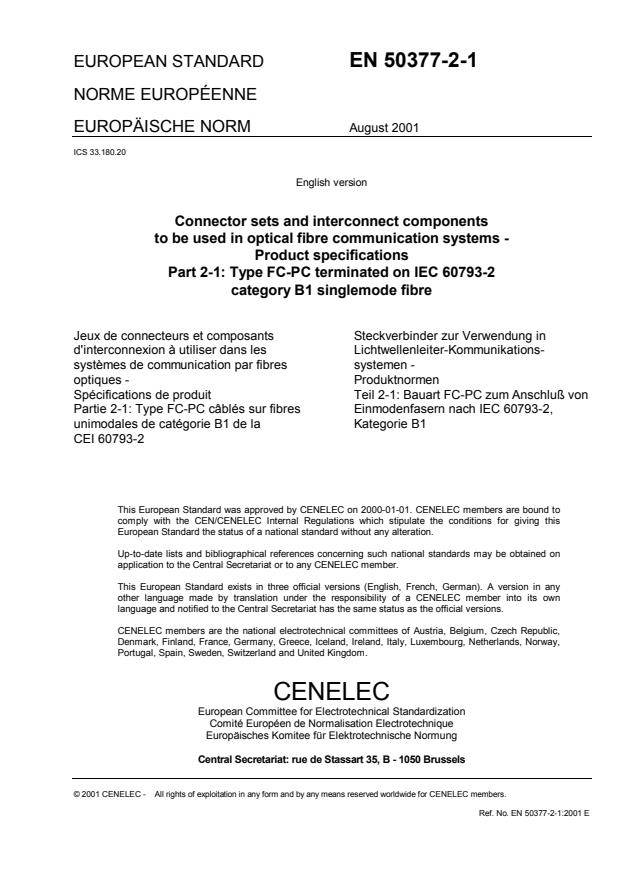
EUROPEAN STANDARD EN 50377-2-1
NORME EUROPÉENNE
EUROPÄISCHE NORM August 2001
ICS 33.180.20
English version
Connector sets and interconnect components
to be used in optical fibre communication systems -
Product specifications
Part 2-1: Type FC-PC terminated on IEC 60793-2
category B1 singlemode fibre
Jeux de connecteurs et composants Steckverbinder zur Verwendung in
d'interconnexion à utiliser dans les Lichtwellenleiter-Kommunikations-
systèmes de communication par fibres systemen -
optiques - Produktnormen
Spécifications de produit Teil 2-1: Bauart FC-PC zum Anschluß von
Partie 2-1: Type FC-PC câblés sur fibres Einmodenfasern nach IEC 60793-2,
unimodales de catégorie B1 de la Kategorie B1
CEI 60793-2
This European Standard was approved by CENELEC on 2000-01-01. CENELEC members are bound to
comply with the CEN/CENELEC Internal Regulations which stipulate the conditions for giving this
European Standard the status of a national standard without any alteration.
Up-to-date lists and bibliographical references concerning such national standards may be obtained on
application to the Central Secretariat or to any CENELEC member.
This European Standard exists in three official versions (English, French, German). A version in any
other language made by translation under the responsibility of a CENELEC member into its own
language and notified to the Central Secretariat has the same status as the official versions.
CENELEC members are the national electrotechnical committees of Austria, Belgium, Czech Republic,
Denmark, Finland, France, Germany, Greece, Iceland, Ireland, Italy, Luxembourg, Netherlands, Norway,
Portugal, Spain, Sweden, Switzerland and United Kingdom.
CENELEC
European Committee for Electrotechnical Standardization
Comité Européen de Normalisation Electrotechnique
Europäisches Komitee für Elektrotechnische Normung
Central Secretariat: rue de Stassart 35, B - 1050 Brussels
© 2001 CENELEC - All rights of exploitation in any form and by any means reserved worldwide for CENELEC members.
Ref. No. EN 50377-2-1:2001 E
Foreword
This European Standard was prepared by the Technical Committee CENELEC TC 86BXA, Fibre optic connectors.
The text of the draft was submitted to the Unique Acceptance Procedure and was approved by CENELEC as
EN 186500 on 2000-01-01. According to the new numbering scheme accepted by the 107th Technical Board of
CENELEC, the standard was renamed EN 50377-2-1.
The following dates were fixed:
- latest date by which the EN has to be implemented
at national level by publication of an identical
national standard or by endorsement (dop) 2002-03-01
- latest date by which the national standards conflicting
with the EN have to be withdrawn (dow) 2003-01-01
__________
- 3 - EN 50377-2-1:2001
PRODUCT SPECIFICATION FOR CONNECTOR SET TO BE USED IN
SINGLE MODE OPTICAL FIBRE COMMUNICATION SYSTEMS
Type: FC-PC terminated on IEC 60793-2 category B1 fibre
Description Performance
Coupling mechanism: screw Application: For use in IEC 61753-2-1
category U and ES 300 671
environments (see 1.3)
Configuration: plug/adaptor/plug Attenuation Grades:
P: ≤0,35dB mean.
(Random Mate)
≤1,0dB
Q: ≤0,30dB mean.
Fibre Category: IEC 60793-2
≤0,60dB for ≥99% of measurements
type B1
Return Loss Grades:
S: ≥26dB
T: ≥35dB
Cable Type see table 3
U: ≥50dB
Related documents:
IEC 61754-13 Basic Standard for Interface Dimensions - Part 13 Type FC/PC
IEC 61753 Performance Standard - Part 1 General and Guidance
EN 186000 Generic Specification for Fibre Optic Connectors
EN 61300- Basic Test and Measurement Procedures
IEC 60793-2 Optical Fibres – Part 2 Product Specifications
IEC 60794-2 Optical Fibre Cables - Part 2 Product Specifications
ETS 300 671 Fibre optical connectors for single-mode optical fibre communication systems.
Outline and maximum dimensions:
61 REF
83 REF
36 MAX 58 MAX
R25 MIN
R25 MIN
CONTENTS
1 Scope . 5
1.1 Product definition. 5
1.2 Intermateability . 5
1.3 Operating environment . 5
1.4 Reliability. 5
1.5 Quality assurance . 6
2 Related documents. 6
3 Description. 6
3.1 Plug . 6
3.2 Adaptor. 6
3.3 Materials . 6
3.4 Dimensions. 7
3.5 Colour and marking. 7
4 Variants. 7
4.1 Terminated plug . 7
4.2 Adaptor. 8
4.3 Identification of variants . 8
5 Dimensional requirements . 10
5.1 Outline dimensions . 10
5.1.1 Plug variants . 10
5.1.2 Adaptor variants . 11
5.2 Mating face and other limit dimensions. 13
5.2.1 Plug . 13
5.2.2 Ferrule endtip geometry after termination. 15
5.2.3 Positioning of fibre core . 17
5.2.4 Control of fibre axis . 18
5.2.5 Adaptor . 19
5.2.6 Pin gauge for adaptor. 21
6 Tests. 22
6.1 Sample size . 22
6.2 Test and measurement methods . 22
6.3 Test sequence. 22
6.4 Pass/fail criteria . 22
7 Test report. 22
8 Testing requirements. 23
8.1 Dimensional requirements. 23
8.2 Optical performance requirements . 23
8.3 Mechanical performance requirements . 25
8.4 Environmental performance requirements . 29
Annex A - Reference connector details. 32
Annex B - Sample size and product sourcing requirements . 32
- 5 - EN 50377-2-1:2001
1Scope
1.1 Product definition
This specification contains the initial, start of life dimensional, optical, mechanical and
environmental performance requirements which a terminated and assembled singlemode
resilient alignment sleeve FC/PC connector set (plug adaptor plug) must meet in order for it to
be categorised as an EN standard product.
Since different variants and grades of performance are permitted, product marking details are
given in 3.5.
1.2 Intermateability
Although all products conforming to the requirements of this specification will intermate, the
resulting level of random attenuation performance will only be ensured in accordance with
Table 1 The intention is that this will be true irrespective of the manufacturing source(s) of the
product.
In all cases, the intermating of plug variants having different attenuation grades will result in an
uncertain level of random attenuation performance.
Similarly, when intermating plug variants having different return loss grades, the resulting level
of return loss cannot be assured to be any better than the worst return loss grade.
Table 1 - Ensured level of random attenuation
Plug variant/attenuation grade P Q
PP
Q Q
1.3 Operating environment
The tests selected combined with the severities and durations are representative of an external
weather protected environment defined by
- IEC 61753-1-2 category U: uncontrolled environment
- ES 300 671 external weather protected environment defined by ES 300 019 [8] classes 3.3,
3.4 and 3.5.
1.4 Reliability
Whilst the anticipated service life expectancy of the product in this environment is 20 years,
compliance with this specification does not guarantee the reliability of the product. This should
be predicted using a recognised reliability assessment programme.
1.5 Quality assurance
Compliance with this specification does not guarantee the manufacturing consistency of the
product. This should be maintained using a recognised quality assurance programme.
2 Related documents
IEC 61754-13 Basic Standard for interface dimensions - Part 13 Type FC/PC
IEC 61753 Performance Standard - Part 1: General and guidance
EN 186000 Generic Specification for fibre optic connectors
EN 61300-X Basic test and measurement pProcedures
IEC 60793-2 Optical fibres – Part 2 Product Specifications
IEC 60794-2 Optical fibre cables - Part 2 Product Specifications
ETS 300-671 Fibre optical connectors for single-mode optical fibre communication
systems
3 Description
The FC/PC connector is a single position plug connector set of plug adaptor plug
configuration characterised by a cylindrical, spring loaded butting ferrule of 2,5 mm typical
diameter and a screw coupling mechanism. The optical alignment mechanism of the connector
is of a resilient sleeve style
3.1 Plug
The plug features a cylindrical zirconia ceramic ferrule and a screw thread coupling
mechanism. It has a single male key that is used to limit and may be used to orientate, the
relative rotation between mated connectors.
A cover (dustcap) to protect the ferrule endface when the connector is in the unmated
condition shall be provided.
3.2 Adaptor
The adaptor has a zirconia ceramic resilient alignment sleeve. The mounting style can be:
i square flange - 4 hole
ii square flange - 2 hole
iii single “d-hole” fixing with back nut
iv double “d-hole” fixing with back nut
Covers (dustcaps) shall be provided to protect each port of the adaptor.
3.3 Materials
Materials which are not specified or which are not specifically described are left to the
discretion of the manufacturer.
- 7 - EN 50377-2-1:2001
3.4 Dimensions
Outline dimensions and other dimensions necessary to ensure intermateability or which affect
performance are specified. All other dimensions are left to the discretion of the manufacturer.
Where the mating face limit dimensions are not in agreement with an IEC Interface Standard
this is clearly stated.
3.5 Colour and marking
Marking of the product shall be in accordance with 2.6.2 of EN 186000 in the following order
of precedence:
a. Identification of manufacturer
b. Manufacturing date code : year/week
c. Manufacturers part number
d. Variant identification number
The following colour scheme is preferred:
Table 2 - Preferred colour scheme
Coupling nut/adaptor Boot
Blue Blue
4 Variants
4.1 Terminated plug
The following variants are permitted:
Table 3 - Plug variants
Variant number Fibre/cable Structure Notes
∅∅∅∅mm
P01 0,7 - 1,4 Buffered fibre
P02 Reinforced Cable
2,0 ± 0,2
P03 Reinforced Cable
2,5 ± 0,2
P04 2,8 ± 0,2 Reinforced Cable
P05 Reinforced Cable
3,0 ± 0,2
P06 3,2 ± 0,2 Reinforced Cable
Q01 0,7 - 1,4 Buffered fibre
Q02 Reinforced Cable
2,0 ± 0,2
Q03 Reinforced Cable
2,5 ± 0,2
Q04 Reinforced Cable
2,8 ± 0,2
Q05 Reinforced Cable
3,0 ± 0,2
Q06 3,2 ± 0,2 Reinforced Cable
4.2 Adaptor
The following variants are permitted:
Table 4 - Adaptor variants
Variant number Format
A01 Square flange 4 hole
A02 Square flange 2 hole
A03 single “d-hole”
A04 double “d-hole”
4.3 Identification of variants
Table 5 - P grade plugs
Variant number Performance grade Identification number
(Return loss)
P01 S EN50377-2-1-P01-S
P01 T EN50377-2-1-P01-T
P01 U EN50377-2-1-P01-U
P02 S EN50377-2-1-P02-S
P02 T EN50377-2-1-P02-T
P02 U EN50377-2-1-P02-U
P03 S EN50377-2-1-P03-S
P03 T EN50377-2-1-P03-T
P03 U EN50377-2-1-P03-U
P04 S EN50377-2-1-P04-S
P04 T EN50377-2-1-P04-T
P04 U EN50377-2-1-P04-U
P05 S EN50377-2-1-P05-S
P05 T EN50377-2-1-P05-T
P05 U EN50377-2-1-P05-U
P06 S EN50377-2-1-P06-S
P06 T EN50377-2-1-P06-T
P06 U EN50377-2-1-P06-U
- 9 - EN 50377-2-1:2001
Table 6 - Q grade plugs
Variant number Performance grade Identification number
(Return loss)
Q01 S EN50377-2-1-Q01-S
Q01 T EN50377-2-1-Q01-T
Q01 U EN50377-2-1-Q01-U
Q02 S EN50377-2-1-Q02-S
Q02 T EN50377-2-1-Q02-T
Q02 U EN50377-2-1-Q02-U
Q03 S EN50377-2-1-Q03-S
Q03 T EN50377-2-1-Q03-T
Q03 U EN50377-2-1-Q03-U
Q04 S EN50377-2-1-Q04-S
Q04 T EN50377-2-1-Q04-T
Q04 U EN50377-2-1-Q04-U
Q05 S EN50377-2-1-Q05-S
Q05 T EN50377-2-1-Q05-T
Q05 U EN50377-2-1-Q05-U
Q06 S EN50377-2-1-Q06-S
Q06 T EN50377-2-1-Q06-T
Q06 U EN50377-2-1-Q06-U
Table 7 - Adaptor variants
Variant Number Performance Grade Identification Number
(Attenuation/Return Loss)
A01 - EN50377-2-1-A01
A02 - EN50377-2-1-A02
A03 - EN50377-2-1-A03
A04 - EN50377-2-1-A04
A05 - EN50377-2-1-A05
5 Dimensional requirements
5.1 Outline dimensions
5.1.1 Plug variants
Variant No. P01/Q01
C
A
B
Ref. Dimensions Note
Min. mm Max.
A - 32
B - 36
C 0,7 1,4
Variant Nos. P02/P03/P04/P05/P06, Q02/Q03/Q04/Q05/Q06
C
A
B
Ref. Dimensions Note
Min. mm Max.
A - 54
B - 58
C 1,8 3,4
Figure 1 - Outline dimensions - Plug
- 11 - EN 50377-2-1:2001
5.1.2 Adaptor variants
Variant No. A01
D
A
K
B
A
C
B
Ref. Dimensions Note
Min. mm Max.
A 9,4 9,6
B 15,0 15,2
C 14,8 15,0
D M8 x 0,75
K 2,15 2,60
Variant No. A02
D
A
K
B
A
C
B
Ref. Dimensions Note
Min. mm Max.
A 9,4 9,6
B 15,0 15,2
C 14,8 15,0
D M8 x 0,75
K 2,15 2,60
Figure 2 -Outline dimensions - adaptor
Variant No. A03
Panel Cut Out
D
F
G
K
H E
C
J
Ref. Dimensions Note
Min. mm Max.
C 14,8 15,0
D M8 x 0,75
K 2,15 2,60
E 9,1 9,4
F 8,8 9,0
G 8,5 8,7
H 8.8 9,0
J 10,9 11,1
Variant No. A04
Panel Cut Out
D
L M
K
H
E
C
J
Ref. Dimensions Note
Min. mm Max.
C 14,8 15,0
D M8 x 0,75
E 9,1 9,4
H 8,8 9,0
J 10,9 11,1
K 2,15 2,60
L 7,9 8,1
M 8,2 8,4
Figure 3 - Outline dimensions - adaptor
- 13 - EN 50377-2-1:2001
5.2 Mating face and other limit dimensions
5.2.1 Plug
i e
f
h
k
l
m m
n
fb fc
fa
Detail A
g
d
j
MECHANICAL REFERENCE PLANE
Ref. Dimensions Note
Min. mm Max.
a 2,4985 2,4995 diameter, 1
b 4,40 4,60 diameter
c 5,80 6,00 diameter
d 2,92 3,42
e(free) 3,75 4,05 4
e(mated) 3,60 - 4
f 1,77 3,00
g M8 x 0,75 - 6H 3
h 0,0 1,00 2
i 3,50 3,55 2,3
j 3,95 4,45
k 1,86 2,14
l -1,00 0,40 2,7
m 0,0 46 degree, 8
n 0,30 0,50
Notes and detail A: see following pages
Figure 4 -Mating face and other limit dimensions.
Notes:
1. The ferrule material is zirconia ceramic. A chamfer or radius is allowed to a maximum depth
of 1,2 mm from the ferrule endface.
2. Dimensions h and i shall be measured with the coupling nut in its most forward position.
3. Dimension g is a metric thread. M8 X 0,75 indicates a thread with a nominal diameter of 8
mm and pitch of 0,75 mm. 6 H represents the class of fit.
4. Dimension e (free) refers to the plug in the unmated condition. Dimension e (mated) varies
according to the axial compression generated when mated. The axial compression force
shall be between 7,8 N and 11,8 N. when dimension e(mated) is between 3,6 and 3,7 mm
5. Surface finish shall be consistent with the associated toleranced dimensions to ensure that
performance requirements are met.
6. All cylindrical components shall be capable of taking up a common axis.
7. Dimension l may be negative (i.e. behind the mechanical reference plane) up to dimension h.
8. The maximum dimension given for “m”, is for a plug having 4 tuning positions. Grade Q
does not imply the use of tuning or define the number of tuning positions. When tuning is
used, the fibre core shall be eccentric towards the key and be located within the section
defined in 5.2.3.
- 15 - EN 50377-2-1:2001
5.2.2 Ferrule endface geometry after termination
Note 6
BK
BG
DETAIL A
A
BF
Note 3
BI
Ref. Dimensions Note
Min. mm Max.
BF 10 25 1,5
BG 1,90 2,26 diameter
BI 25 35 degree
BK -0.0001 Figure 4b 2,4
Figure 5a - Ferrule endface geometry - after termination
Allowable undercut versus ferrule endface radius
10 11 12 13 14 15 16 17 18 19 20 21 22 23 24 25
Ferrule Endface Radius (mm)
3 2
Allowable undercut BK = -0,02BF +1.3BF - 31BF + 325
Figure 5b - Allowable undercut versus endface radius
Notes: See following page
Allowable undercut (nm)
Notes:
1. Dome eccentricity of the spherically polished endface shall be less than 50 μm.
2. The negative dimension refers to fibre protrusion.
3. A chamfer or radius is allowed to a maximum depth of 1,2 mm from the ferrule endface.
4. Dimension BK shall be measured in accordance with EN 61300-3-23
5. The radius shall be measured over a diameter of 0,25 mm.
6. Visual examination with x200 magnification of fibre end surface after cleaning, no defects
dirt or residues shall be visible in the 10µm diameter core zone.
- 17 - EN 50377-2-1:2001
5.2.3 Positioning of fibre core
The shaded areas in the figure below denote the target area in which the fibre core must be
positioned during the plug termination process. To obtain the performances indicated by grade
P or Q, the fibre core must be positioned within the shaded segments shown.
Key
b b
c
a
d
Variant P Variant Q
Ref. Dimensions Note
Min. mm Max.
Grade P Grade Q
a - 0,0008 diameter, see 5.2.4
b - 50 degree,
c - 0,0015 see 5.2.4
d - 0,0030 diameter, see 5.2.4
Notes:
1. Grade Q does not imply the use of tuning or define the
...