

IEC 60079-1:2026
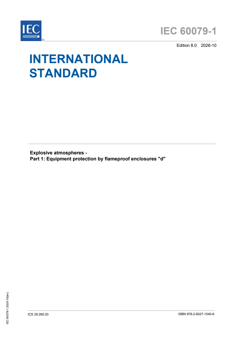
(Main)Explosive atmospheres - Part 1: Equipment protection by flameproof enclosures "d"
- Abstract
IEC 60079-1:2026 contains specific requirements for the construction and testing of Ex Equipment and Ex Components with the Type of Protection flameproof enclosure "d", intended for use in explosive gas atmospheres.
This document supplements and modifies the general requirements of IEC 60079‑0. Where a requirement of this document conflicts with a requirement of IEC 60079‑0, the requirement of this document takes precedence.
This eighth edition constitutes a technical revision. Refer to the Foreword of the document for a complete listing of the technical changes between edition 8.0 and the previous edition of the document.
Users of this document are advised that interpretation sheets clarifying the interpretation of this document can be published. Interpretation sheets are available from the IEC webstore and can be found in the "history" tab of the page for each document.
- Status
- Published
- Publication Date
- 08-Oct-2026
- Technical Committee
- TC 31 - Equipment for explosive atmospheres
- Drafting Committee
- MT 60079-1 - TC 31/MT 60079-1
- Current Stage
- PPUB - Publication issued
- Start Date
- 09-Oct-2026
- Completion Date
- 30-Oct-2026
Buy Documents
IEC 60079-1:2026 - Explosive atmospheres - Part 1: Equipment protection by flameproof enclosures "d"

IEC 60079-1:2026 - Atmosphères explosives - Partie 1: Protection des appareils par enveloppes antidéflagrantes "d"
IEC 60079-1:2026 is an IEC International Standard for explosive atmospheres. It specifies how to construct and test Ex Equipment and Ex Components with the Type of Protection flameproof enclosure "d" for use in explosive gas atmospheres. The document supplements IEC 60079-0, and where the two conflict, IEC 60079-1:2026 takes precedence.
What does IEC 60079-1:2026 specify?
IEC 60079-1:2026 sets out the detailed requirements for flameproof enclosures "d", including enclosure construction, joint design, entry devices, testing, marking and instructions. It applies to Ex Equipment and Ex Components and is organized into clauses 1 to 22, followed by annexes A to I.
| Annex | What it covers |
|---|---|
| A | Additional requirements for crimped ribbon elements and multiple screen elements of breathing and draining devices |
| B | Additional requirements for elements with non-measurable paths in breathing and draining devices |
| C | Additional requirements for flameproof entry devices |
| D | Empty flameproof enclosures as Ex Components |
| E | Cells and batteries used in flameproof enclosures |
| F | Mechanical properties for screws and nuts |
| G | Additional requirements for flameproof enclosures with a containment system |
| H | Electric machines used with converters |
| I | Recommendation to improve the effectiveness of the determination of explosion pressure |
The main body covers the general protection levels, flameproof joints, sealed joints, operating rods, electric machines, breathing and draining devices, fasteners, materials, entries, batteries, testing, switchgear for Group I, lampholders, non-metallic enclosures, marking and instructions.
What are the key requirements of IEC 60079-1:2026?
IEC 60079-1:2026 is mainly about keeping an internal explosion inside the enclosure while preventing ignition of the surrounding atmosphere. In practice, that means the enclosure geometry, materials, fasteners, entries and test results all have to work together as part of the protection concept.
Protection levels and overall design
IEC 60079-1:2026 defines three Levels of Protection for flameproof enclosure "d": da, db and dc, corresponding to equipment protection levels (EPL) Ma or Ga, Mb or Gb, and Gc. Clause 4 says the document applies to all levels unless a later clause states a special rule. For a designer or certifier, this means the intended level must be fixed early because it drives the construction and testing route.
Level of Protection "da" is a special case for catalytic sensors in certain gas detection equipment. The sensor volume is limited, the conductors must enter through a sealed joint in the sensor wall, the breathing device must be bonded or press-fitted so that gaps are eliminated, and the sensor must be supplied by an "ia" circuit with a limited dissipated power. Clause 4 also requires a higher number of non-transmission tests. In practice, "da" is not a general-purpose flameproof solution, but a narrow one for specific gas detection applications.
Level of Protection "db" follows the general requirements of the document except where the "da" and "dc" rules add further conditions. Level of Protection "dc" has its own construction and type-test requirements in Clause 4.4. That matters because the same flameproof enclosure family can be assessed at different protection levels, but not with the same evidence package.
Flameproof joints, sealed joints and moving parts
Clause 5 is the core of the standard. It requires all flameproof joints, whether permanently closed or opened during installation or maintenance, to meet the dimensional requirements and the relevant tests. The clause covers non-threaded joints, threaded joints, gaskets, capillaries and a range of joint geometries such as spigot, cylindrical, conical, serrated and multi-step forms. For the user, this means the flamepath is a controlled design feature, not an incidental manufacturing detail.
The document uses minimum lengths, maximum gaps and thread engagement rules to define flamepath performance. When the joint dimensions are outside the standard limits, the certificate and instructions have to carry the extra conditions of use, including the "X" suffix where applicable. That is important for maintenance and repair because the enclosure may depend on exact dimensions that must be preserved over its life.
Clause 6 covers cemented, fused glass, welded, brazed and moulded sealed joints. Clause 7 covers operating rods, and Clause 8 adds extra requirements for electric machines, including shaft joints and bearings. In practice, any moving penetration through the enclosure wall has to be treated as part of the explosion-protection design.
Entries, fasteners and materials
Clause 11 controls fasteners and openings. Fasteners that pass through enclosure walls have to form a flameproof joint or be permanently fixed, and special fasteners are required when they are accessible from outside and needed for assembly. Plastic fasteners and light-alloy fasteners are not permitted. Blind holes, thread inserts and openings for optional devices all have specific conditions. This matters because a small fastening detail can affect the integrity of the whole enclosure.
Clause 12 sets material rules. Cast iron must be at least grade 150, zinc and zinc alloys with 80 % zinc or more are not allowed, and some insulating materials in Group I enclosures need a comparative tracking index (CTI) of at least 400 M when they are exposed to electrical stresses capable of arcing. Liquids are allowed only when they do not create a more hazardous atmosphere by decomposition, or when the enclosure passes the relevant tests for the mixture produced. For buyers and manufacturers, these rules affect material selection, supplier qualification and change control.
Clause 13 covers threaded and non-threaded entries, cable glands, conduit sealing devices, plugs and sockets, bushings, blanking elements, thread adapters and fluid entries. Separate entries may be treated as Ex Equipment or Ex Components depending on type and Group, while non-threaded entries for Groups IIA and IIB are only Ex Components. Annex C adds the detailed construction and test requirements. In practice, the entry device is not an accessory - it is part of the certified protection system.
Verification, type tests and routine tests
Clauses 15 to 17 define verification, type tests and routine tests. Type testing starts with determination of explosion pressure, followed by overpressure testing and the test for non-transmission of an internal ignition. Non-metallic enclosures and parts add an erosion-by-flame test. Clause 17 requires routine testing to confirm pressure resistance and freedom from holes or cracks, and it provides special treatment for welded or brazed joints and batch testing. That is the basis for both certification and production control.
The test program changes with the equipment family. Clause 16 gives separate paths for Groups I, IIA, IIB and IIC, and for flameproof enclosures with breathing and draining devices. Clause 15 also ties surface-temperature determination to defined overload or malfunction conditions for luminaires and electric machines. For the practical user, this means the test plan has to match the exact equipment type, not just the enclosure shape.
Special equipment, marking and instructions
Clause 18 deals with Group I switchgear that is opened on site and can produce arcs or sparks. Clause 19 covers lampholders and lamp caps that form a flameproof enclosure together, and Clause 20 applies special rules to non-metallic enclosures and non-metallic parts, including tracking, creepage and flame-erosion testing. These clauses matter where the enclosure is part of a larger functional assembly rather than a simple housing.
Clause 21 sets marking for da, db and dc, plus caution, warning and informative markings. Clause 22 requires instructions to include flamepath details where needed, selection guidance for entry and breathing/draining devices at higher reference pressures, information for non-threaded entries, and containment-system instructions where applicable. In practice, the label and the instructions carry part of the safety case.
What terms does IEC 60079-1:2026 define?
- flameproof enclosure "d" - an enclosure that contains parts able to ignite an explosive gas atmosphere, withstands the pressure of an internal explosion, prevents transmission of the explosion to the outside atmosphere, and avoids external surface temperatures capable of ignition.
- flameproof joint or flamepath - the place where enclosure parts meet in a way intended to stop flame transmission from inside to outside.
- sealed joint - a joint sealed by a material intended to prevent transmission of an internal explosion to the surrounding explosive gas atmosphere.
- containment system - the part of the equipment that contains a flammable or non-flammable substance that can become an internal source of release.
- internal source of release - a point or location from which a substance can be released into the enclosure so that an explosive gas atmosphere could form.
- quick-acting door or quick-acting cover - a door or cover that opens or closes by a simple operation, with a separate locking or unlocking stage.
- door fixed by threaded fasteners - a door or cover that requires screws, studs, bolts or nuts to open or close.
Who uses IEC 60079-1:2026?
IEC 60079-1:2026 is used by manufacturers of Ex Equipment and Ex Components, certification bodies, and test laboratories that assess flameproof designs. It is also used by design engineers, quality managers and buyers who need to specify or review flameproof enclosures, entry devices, cable glands, bushings, blanking elements, batteries, electric machines, switchgear and luminaires.
The standard is relevant in industries that use explosive gas atmospheres, including Group I applications and Group II gas applications. It is particularly important for gas detection equipment, electric machines, switchgear, lighting equipment and enclosure component suppliers because the details of joints, entries, markings and tests directly affect certification and maintenance.
What changed in IEC 60079-1:2026 from the previous edition?
IEC 60079-1:2026 is the eighth edition and the foreword describes it as a technical revision. The change list visible in the document includes a clarification for the application of bushing requirements to moulded joints, removal of the limitation that previously did not allow the use of a blanking element with a thread adaptor, and a significant rewrite of Annex G. The foreword also states that the full list of technical changes is given there.
Which standards are used with IEC 60079-1:2026?
IEC 60079-1:2026 refers to several standards that supply general requirements, methods or component definitions used in flameproof design and testing:
- IEC 60079-0 - the general requirements baseline for Ex Equipment and Ex Components.
- IEC 60079-7 - increased safety requirements used for clearances, creepage distances and some lampholder and insulation provisions.
- IEC 60079-11 - intrinsic safety requirements used for certain circuits and isolation arrangements.
- IEC 60061 - lamp caps, lamp holders and gauges for interchangeability and safety.
- IEC 60086-1 - primary batteries, used in Annex E for acceptable cell systems.
- IEC 60127 and ANSI/UL 248 - miniature and low-voltage fuse standards used where fuse selection matters.
- ISO 185 - cast iron classification for material selection.
- ISO 228-1, ISO 965-1 and ISO 965-3 - thread dimensions and tolerances for threaded entries and joints.
- ANSI/ASME B1.20.1 - NPT pipe thread requirements.
- ISO 2859-1 - sampling by attributes for batch testing.
- ISO 4003 and ASTM F316 - bubble-test and pore-size methods for sintered and porous elements.
- ISO 80000-1 - quantity and unit rules used when rounding dimensions.
What does the IEC 60079-1:2026 document contain?
IEC 60079-1:2026 contains many dimensioned tables, test conditions and construction examples that are central to design and certification work. The tables cover joint lengths and gaps, threaded joint engagement, batch sampling, static pressures, battery systems and tightening torques, while the figures illustrate flange, spigot, cylindrical, conical and serrated joints, gasket arrangements, blanking elements and sealing-test setups.
The annexes add detailed methods for breathing and draining devices, entry devices, empty enclosures as Ex Components, batteries, containment systems and electric machines with converters. The document also includes acceptance criteria, routine-test options and marking text that manufacturers and certifiers use to document the approved configuration.
Relations
- Effective Date
- 05-Sep-2023
- Revises
IEC 60079-1:2014 - Explosive atmospheres - Part 1: Equipment protection by flameproof enclosures "d" - Effective Date
- 05-Sep-2023
- Effective Date
- 05-Sep-2023
Buy Documents
IEC 60079-1:2026 - Explosive atmospheres - Part 1: Equipment protection by flameproof enclosures "d"
IEC 60079-1:2026 - Atmosphères explosives - Partie 1: Protection des appareils par enveloppes antidéflagrantes "d"
Get Certified
Connect with accredited certification bodies for this standard

IMQ S.p.A. (Certification)
Italian electrical product certification.

SLG Prüf- und Zertifizierungs GmbH
German testing and certification body.

UL Solutions
Global safety science company with testing, inspection and certification.
Sponsored listings
Frequently Asked Questions
IEC 60079-1:2026 is a standard published by the International Electrotechnical Commission (IEC). Its full title is "Explosive atmospheres - Part 1: Equipment protection by flameproof enclosures "d"". This standard covers: IEC 60079-1:2026 contains specific requirements for the construction and testing of Ex Equipment and Ex Components with the Type of Protection flameproof enclosure "d", intended for use in explosive gas atmospheres. This document supplements and modifies the general requirements of IEC 60079‑0. Where a requirement of this document conflicts with a requirement of IEC 60079‑0, the requirement of this document takes precedence. This eighth edition constitutes a technical revision. Refer to the Foreword of the document for a complete listing of the technical changes between edition 8.0 and the previous edition of the document. Users of this document are advised that interpretation sheets clarifying the interpretation of this document can be published. Interpretation sheets are available from the IEC webstore and can be found in the "history" tab of the page for each document.
IEC 60079-1:2026 contains specific requirements for the construction and testing of Ex Equipment and Ex Components with the Type of Protection flameproof enclosure "d", intended for use in explosive gas atmospheres. This document supplements and modifies the general requirements of IEC 60079‑0. Where a requirement of this document conflicts with a requirement of IEC 60079‑0, the requirement of this document takes precedence. This eighth edition constitutes a technical revision. Refer to the Foreword of the document for a complete listing of the technical changes between edition 8.0 and the previous edition of the document. Users of this document are advised that interpretation sheets clarifying the interpretation of this document can be published. Interpretation sheets are available from the IEC webstore and can be found in the "history" tab of the page for each document.
IEC 60079-1:2026 is classified under the following ICS (International Classification for Standards) categories: 29.260.20 - Electrical apparatus for explosive atmospheres. The ICS classification helps identify the subject area and facilitates finding related standards.
IEC 60079-1:2026 has the following relationships with other standards: It is inter standard links to IEC 60079-1:2014/ISH1:2020, IEC 60079-1:2014, IEC 60079-1:2014/COR1:2018. Understanding these relationships helps ensure you are using the most current and applicable version of the standard.
IEC 60079-1:2026 is available in PDF format for immediate download after purchase. The document can be added to your cart and obtained through the secure checkout process. Digital delivery ensures instant access to the complete standard document.
Standards Content (Sample)
IEC 60079-1 ®
Edition 8.0 2026-10
INTERNATIONAL
STANDARD
Explosive atmospheres -
Part 1: Equipment protection by flameproof enclosures "d"
ICS 29.260.20 ISBN 978-2-8327-1540-6
All rights reserved. Unless otherwise specified, no part of this publication may be reproduced or utilized in any form or
by any means, electronic or mechanical, including photocopying and microfilm, without permission in writing from either
IEC or IEC's member National Committee in the country of the requester. If you have any questions about IEC copyright
or have an enquiry about obtaining additional rights to this publication, please contact the address below or your local
IEC member National Committee for further information.
IEC Secretariat Tel.: +41 22 919 02 11
3, rue de Varembé info@iec.ch
CH-1211 Geneva 20 www.iec.ch
Switzerland
About the IEC
The International Electrotechnical Commission (IEC) is the leading global organization that prepares and publishes
International Standards for all electrical, electronic and related technologies.
About IEC publications
The technical content of IEC publications is kept under constant review by the IEC. Please make sure that you have the
latest edition, a corrigendum or an amendment might have been published.
IEC publications search - IEC Products & Services Portal - products.iec.ch
webstore.iec.ch/advsearchform Discover our powerful search engine and read freely all the
The advanced search enables to find IEC publications by a publications previews, graphical symbols and the glossary.
variety of criteria (reference number, text, technical With a subscription you will always have access to up to date
committee, …). It also gives information on projects, content tailored to your needs.
replaced and withdrawn publications.
Electropedia - www.electropedia.org
The world's leading online dictionary on electrotechnology,
IEC Just Published - webstore.iec.ch/justpublished
Stay up to date on all new IEC publications. Just Published containing more than 22 500 terminological entries in English
details all new publications released. Available online and and French, with equivalent terms in 25 additional languages.
once a month by email. Also known as the International Electrotechnical Vocabulary
(IEV) online.
IEC Customer Service Centre - webstore.iec.ch/csc
If you wish to give us your feedback on this publication or
need further assistance, please contact the Customer
Service Centre: sales@iec.ch.
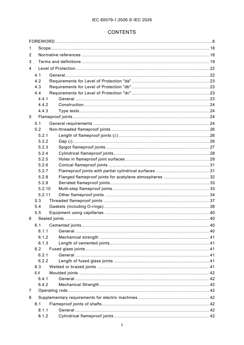
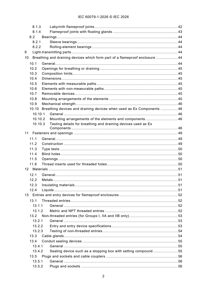
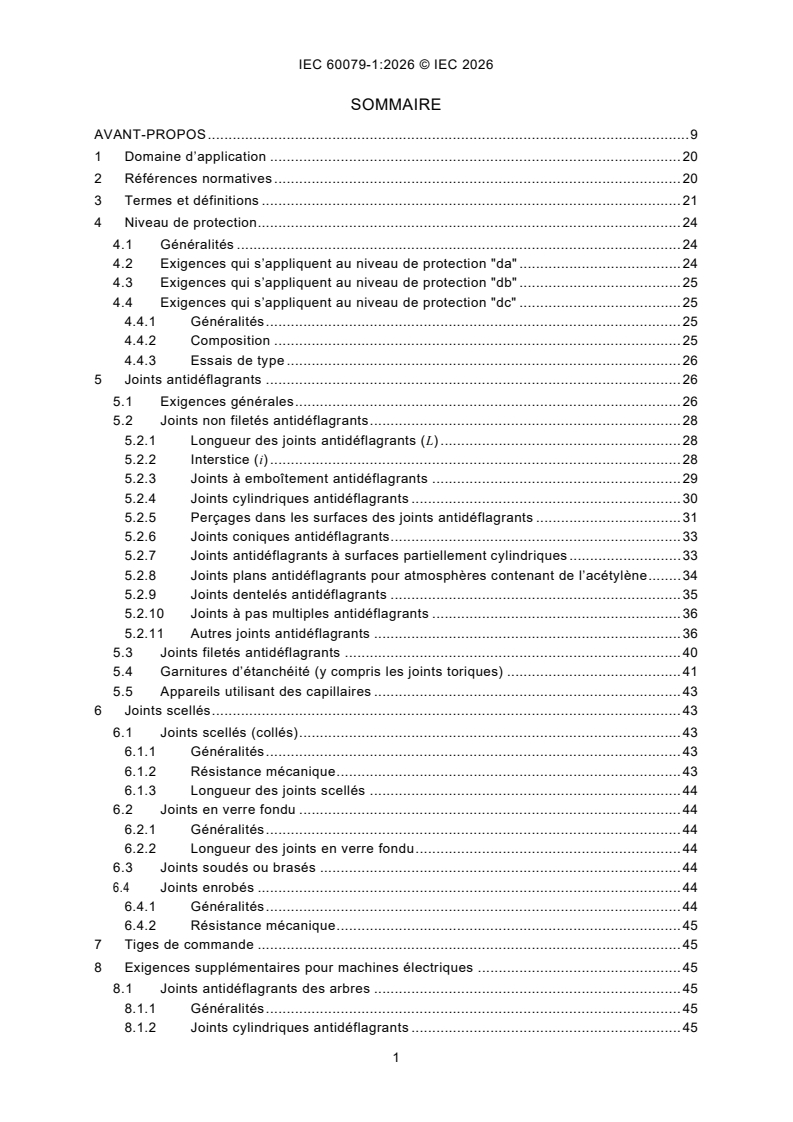
CONTENTS
FOREWORD . 8
1 Scope . 18
2 Normative references . 18
3 Terms and definitions . 19
4 Level of Protection. 22
4.1 General . 22
4.2 Requirements for Level of Protection "da" . 23
4.3 Requirements for Level of Protection "db" . 23
4.4 Requirements for Level of Protection "dc" . 23
4.4.1 General . 23
4.4.2 Construction . 24
4.4.3 Type tests. 24
5 Flameproof joints . 24
5.1 General requirements . 24
5.2 Non-threaded flameproof joints . 26
5.2.1 Length of flameproof joints (L) . 26
5.2.2 Gap (i) . 26
5.2.3 Spigot flameproof joints . 27
5.2.4 Cylindrical flameproof joints . 28
5.2.5 Holes in flameproof joint surfaces . 29
5.2.6 Conical flameproof joints . 31
5.2.7 Flameproof joints with partial cylindrical surfaces . 31
5.2.8 Flanged flameproof joints for acetylene atmospheres . 32
5.2.9 Serrated flameproof joints . 33
5.2.10 Multi-step flameproof joints . 33
5.2.11 Other flameproof joints . 34
5.3 Threaded flameproof joints . 37
5.4 Gaskets (including O-rings) . 38
5.5 Equipment using capillaries . 40
6 Sealed joints . 40
6.1 Cemented joints . 40
6.1.1 General . 40
6.1.2 Mechanical strength . 41
6.1.3 Length of cemented joints . 41
6.2 Fused glass joints . 41
6.2.1 General . 41
6.2.2 Length of fused glass joints . 41
6.3 Welded or brazed joints . 41
6.4 Moulded joints . 42
6.4.1 General . 42
6.4.2 Mechanical Strength . 42
7 Operating rods. 42
8 Supplementary requirements for electric machines . 42
8.1 Flameproof joints of shafts . 42
8.1.1 General . 42
8.1.2 Cylindrical flameproof joints . 42
8.1.3 Labyrinth flameproof joints . 42
8.1.4 Flameproof joints with floating glands . 43
8.2 Bearings . 44
8.2.1 Sleeve bearings . 44
8.2.2 Rolling-element bearings . 44
9 Light-transmitting parts . 44
10 Breathing and draining devices which form part of a flameproof enclosure . 44
10.1 General . 44
10.2 Openings for breathing or draining . 45
10.3 Composition limits . 45
10.4 Dimensions . 45
10.5 Elements with measurable paths . 45
10.6 Elements with non-measurable paths . 45
10.7 Removable devices . 45
10.8 Mounting arrangements of the elements . 45
10.9 Mechanical strength . 46
10.10 Breathing devices and draining devices when used as Ex Components . 46
10.10.1 General . 46
10.10.2 Mounting arrangements of the elements and components . 46
10.10.3 Testing details for breathing and draining devices used as Ex
Components . 46
11 Fasteners and openings . 49
11.1 General . 49
11.2 Construction . 49
11.3 Type tests . 50
11.4 Blind holes . 50
11.5 Openings . 50
11.6 Thread inserts used for threaded holes . 50
12 Materials . 51
12.1 General . 51
12.2 Metals . 51
12.3 Insulating materials . 51
12.4 Liquids . 51
13 Entries and entry devices for flameproof enclosures . 52
13.1 Threaded entries . 52
13.1.1 General . 52
13.1.2 Metric and NPT threaded entries . 52
13.2 Non-threaded entries (for Groups I, IIA and IIB only). 53
13.2.1 General . 53
13.2.2 Entry and entry device specifications . 53
13.2.3 Testing of non-threaded entries . 54
13.3 Cable glands . 54
13.4 Conduit sealing devices . 55
13.4.1 General . 55
13.4.2 Sealing device such as a stopping box with setting compound . 55
13.5 Plugs and sockets and cable couplers . 56
13.5.1 General . 56
13.5.2 Plugs and sockets . 56
13.6 Bushings . 56
13.7 Blanking elements . 57
13.7.1 General . 57
13.7.2 Enclosures with multiple entries . 57
13.7.3 Ex Component blanking elements . 57
13.7.4 Documentation . 57
13.8 Thread adapters . 57
13.9 Fluid entries . 57
14 Cells and batteries used in flameproof enclosures . 57
15 Verification and tests . 57
16 Type tests . 58
16.1 General . 58
16.2 Tests of ability of the enclosure to withstand pressure . 59
16.2.1 General . 59
16.2.2 Determination of explosion pressure (reference pressure) . 60
16.2.3 Overpressure test . 62
16.3 Test for non-transmission of an internal ignition . 64
16.3.1 General . 64
16.3.2 Equipment of Groups I, IIA and IIB . 67
16.3.3 Equipment of Group lIC . 68
16.4 Tests of flameproof enclosures with breathing and draining devices . 70
16.4.1 General . 70
16.4.2 Tests of ability of the enclosure to withstand pressure . 70
16.4.3 Thermal tests. 71
16.4.4 Test for non-transmission of an internal ignition . 71
16.5 Tests for Level of Protection "dc" . 72
16.5.1 General . 72
16.5.2 Preparation of samples . 72
16.5.3 Test conditions . 73
17 Routine tests . 74
17.1 General . 74
17.2 Enclosures not incorporating a welded or brazed joints . 75
17.3 Enclosures incorporating a welded or brazed joint . 75
17.4 Bushings not specific to one flameproof enclosure . 75
17.5 Acceptance criteria . 75
17.6 Batch testing . 76
18 Switchgear for Group I . 76
18.1 General . 76
18.2 Means of isolation . 76
18.3 Doors or covers . 77
18.3.1 Quick-acting doors or covers . 77
18.3.2 Doors or covers fixed by threaded fasteners . 77
18.3.3 Threaded doors or covers . 77
19 Lampholders and Iamp caps . 77
19.1 General . 77
19.2 Device preventing lamps working loose. 77
19.3 Holders and caps for lamps with cylindrical caps . 77
19.4 Lampholders for lamps with threaded lamp caps . 77
20 Non-metallic enclosures and non-metallic parts of enclosures . 78
20.1 General . 78
20.2 Materials . 78
20.3 Requirements for type tests . 78
20.4 Test of erosion by flame . 78
21 Marking . 79
21.1 General . 79
21.2 Caution and warning markings . 79
21.3 Informative markings . 79
22 Instructions . 80
Annex A (normative) Additional requirements for crimped ribbon elements and multiple
screen elements of breathing and draining devices . 81
A.1 Material . 81
A.2 Path dimensions . 81
A.3 Type tests . 81
Annex B (normative) Additional requirements for elements, with non-measurable paths
of breathing and draining devices . 82
B.1 Sintered metal elements . 82
B.1.1 Material . 82
B.1.2 Maximum bubble test pore size. 82
B.1.3 Documentation . 82
B.2 Pressed metal wire elements . 82
B.2.1 Material . 82
B.2.2 Maximum bubble test pore size. 82
B.2.3 Documentation . 83
B.3 Metal foam elements . 83
B.3.1 Material . 83
B.3.2 Maximum bubble test pore size. 83
B.3.3 Documentation . 83
Annex C (normative) Additional requirements for flameproof entry devices . 84
C.1 General . 84
C.2 Construction requirements . 84
C.2.1 Sealing methods . 84
C.2.2 Flameproof joints . 86
C.2.3 Construction requirements for Ex blanking elements . 87
C.2.4 Construction requirements for Ex thread adapters . 89
C.3 Type tests . 89
C.3.1 Sealing test . 89
C.3.2 Test of mechanical strength . 91
C.3.3 Type tests for Ex blanking elements . 92
C.3.4 Type tests for Ex thread adapters . 92
Annex D (normative) Empty flameproof enclosures as Ex Components . 94
D.1 General . 94
D.2 Introductory remarks . 94
D.3 Ex Component enclosure requirements . 94
D.3.1 General . 94
D.3.2 Electric machines . 94
D.3.3 Mounting and location of internal components . 94
D.3.4 Drilling of holes. 95
D.3.5 Determination of explosion pressure (reference pressure) . 95
D.3.6 Overpressure test . 95
D.3.7 Routine test . 95
D.3.8 Marking . 95
D.3.9 Ex Component enclosure certificate . 96
D.4 Utilization of an Ex Component enclosure certificate to prepare an Ex
Equipment certificate . 96
D.4.1 Procedure . 96
D.4.2 Application of the Schedule of Limitations . 96
Annex E (normative) Cells and batteries used in flameproof "db" enclosures . 97
E.1 Introductory remarks . 97
E.2 Acceptable electrochemical systems . 97
E.3 General requirements for cells or batteries inside flameproof enclosures . 100
E.3.1 General . 100
E.3.2 Restrictions of use . 100
E.3.3 Marking . 100
E.3.4 Mounting . 100
E.3.5 Cells in series . 101
E.3.6 Cells in parallel . 101
E.3.7 Cells in series connected in parallel . 101
E.3.8 No additional protection needed . 101
E.4 Arrangement of safety devices . 101
E.4.1 Protection against excessive temperature and excessive
discharging/charging current . 101
E.4.2 Protection against cell polarity reversal or reverse charging by another
cell in the same battery . 102
E.4.3 Prevention of inadvertent charging of a battery by other voltage sources
in the enclosure . 103
E.5 Recharging of secondary cells inside flameproof enclosures . 103
E.6 Ratings of protective components used as safety devices . 104
Annex F (informative) Mechanical properties for screws and nuts . 105
Annex G (normative) Additional requirements for flameproof enclosures with a
containment system . 106
G.1 General . 106
G.2 Release conditions . 109
G.2.1 No release . 109
G.2.2 Limited release of a gas or vapour . 109
G.2.3 Limited release of a liquid . 109
G.3 Design requirements for the containment system . 109
G.3.1 General design requirements . 109
G.3.2 Infallible containment system . 110
G.3.3 Limited release containment system . 110
G.4 Type tests for the containment system . 112
G.4.1 Overpressure test . 112
G.4.2 Leakage test . 112
G.4.3 Limited release venting test . 113
G.5 Routine tests for containment systems . 113
G.5.1 Infallible containment systems . 113
G.5.2 Limited release containment systems . 113
Annex H (normative) Requirements for electric machines used with converters . 114
H.1 General . 114
H.2 Construction requirements for bearings . 114
H.3 Temperature requirements . 114
Annex I (informative) Recommendation to improve the effectiveness of the
determination of explosion pressure. 115
I.1 General . 115
I.2 Aspects to improve consistency . 115
Bibliography . 118
Figure 1 – Example of a regular shaped waveform . 21
Figure 2 – Example of an irregular shaped waveform . 21
Figure 3 – Example of construction for indirect checking of a flanged Group I
flameproof joint . 27
Figure 4 – Example of spigot flameproof joint . 28
Figure 5 – Examples of Cylindrical flameproof joints . 28
Figure 6 – Holes in surfaces of flanged flameproof joints, example 1 . 29
Figure 7 – Holes in surfaces of flanged flameproof joints, example 2 . 29
Figure 8 – Holes in surfaces of flanged flameproof joints, example 3 . 30
Figure 9 – Holes in surfaces of spigot flameproof joints, example 1 . 30
Figure 10 – Holes in surfaces of spigot flameproof joints, example 2 . 31
Figure 11 – Holes in surfaces of spigot flameproof joints, example 3 . 31
Figure 12 – Example of a flameproof joint with partial cylindrical surfaces . 32
Figure 13 – Example of a flanged flameproof joint with a dynamically increased gap . 32
Figure 14 – Example of serrated flameproof joint . 33
Figure 15 – An example of an "other flameproof joint" that incorporates flamepaths not
addressed elsewhere in this document . 35
Figure 16 – Illustration of the requirements concerning gaskets – Example 1 . 39
Figure 17 – Illustration of the requirements concerning gaskets – Example 2 . 39
Figure 18 – Illustration of the requirements concerning gaskets – Example 3 . 39
Figure 19 – Illustration of the requirements concerning gaskets – Example 4 . 39
Figure 20 – Illustration of the requirements concerning gaskets – Example 5 . 39
Figure 21 – Illustration of the requirements concerning gaskets – Example 6 . 39
Figure 22 – Illustration of the requirements concerning gaskets – Example 7 . 40
Figure 23 – Example of cylindrical flameproof joint for shaft of rotating electric machine . 43
Figure 24 – Example of labyrinth flameproof joint for shaft of rotating electric machine . 43
Figure 25 – Example of flameproof joint with floating gland for shaft of rotating electric
machine . 43
Figure 26 – Flameproof joints of shaft glands of electric machines . 43
Figure 27 – Component test rig for breathing and draining devices . 47
Figure 28 – Example of representation of required information . 54
Figure C.1 – Examples of blanking elements for unused entries. 88
Figure C.2 – Device for the sealing tests for cable glands . 90
Figure E.1 – Fitting of diode arrangement for three cells in series . 102
Figure E.2 – Fitting of blocking diodes to meet E.4.3 (third example) . 103
Figure G.1 – Example of a flameproof enclosure with an infallible containment system . 107
Figure G.2 – Example of a flameproof enclosure with a limited release containment
system without flow limiting devices . 107
Figure G.3 – Example of a flameproof enclosure with a limited release containment
system with a flow limiting device . 108
Figure G.4 – Example of a flameproof enclosure with a limited release containment
system (limited release in normal operation) with a flow limiting device . 108
Table 1 – Number of non-transmission tests for Level of Protection "da" . 23
Table 2 – Minimum length of flameproof joints and maximum gaps for enclosures to be
used in Groups I, IIA and IIB . 36
Table 3 – Minimum length of flameproof joints and maximum gaps for enclosures to be
used in Group IIC . 37
Table 4 – Cylindrical threaded flameproof joints . 38
Table 5 – Taper threaded flameproof joints . 38
Table 6 – Conditions for the determination of maximum surface temperature . 58
Table 7 – Test factors for reduced ambient conditions . 61
Table 8 – Relative pressures when reference pressure determination has been
impracticable . 63
Table 9 – Reduction in length of a threaded flameproof joint for non-transmission test. 65
Table 10 – Test factors to increase test pressure or test gap (i ) . 66
E
Table 11 – Minimum distance of any obstacle from flameproof flanged flameproof joints . 66
Table 12 – Gas/air mixtures . 68
Table 13 – Static pressures . 74
Table 14 – Text of caution or warning markings . 79
Table 15 – Text of informative markings . 79
Table C.1 – Tightening torque values, metric . 93
Table C.2 – Tightening torque values, NPT . 93
Table E.1 – Acceptable primary cells . 98
Table E.2 – Acceptable secondary cells . 99
Table F.1 – Mechanical properties for screws and nuts . 105
Table G.1 – Overpressure test parameters . 112
INTERNATIONAL ELECTROTECHNICAL COMMISSION
____________
Explosive atmospheres -
Part 1: Equipment protection by flameproof enclosures "d"
FOREWORD
1) The International Electrotechnical Commission (IEC) is a worldwide organization for standardization comprising
all national electrotechnical committees (IEC National Committees). The object of IEC is to promote international
co-operation on all questions concerning standardization in the electrical and electronic fields. To this end and
in addition to other activities, IEC publishes International Standards, Technical Specifications, Technical Reports,
Publicly Available Specifications (PAS) and Guides (hereafter referred to as "IEC Publication(s)"). Their
preparation is entrusted to technical committees; any IEC National Committee interested in the subject dealt with
may participate in this preparatory work. International, governmental and non-governmental organizations liaising
with the IEC also participate in this preparation. IEC collaborates closely with the International Organization for
Standardization (ISO) in accordance with conditions determined by agreement between the two organizations.
2) The formal decisions or agreements of IEC on technical matters express, as nearly as possible, an international
consensus of opinion on the relevant subjects since each technical committee has representation from all
interested IEC National Committees.
3) IEC Publications have the form of recommendations for international use and are accepted by IEC National
Committees in that sense. While all reasonable efforts are made to ensure that the technical content of IEC
Publications is accurate, IEC cannot be held responsible for the way in which they are used or for any
misinterpretation by any end user.
4) In order to promote international uniformity, IEC National Committees undertake to apply IEC Publications
transparently to the maximum extent possible in their national and regional publications. Any divergence between
any IEC Publication and the corresponding national or regional publication shall be clearly indicated in the latter.
5) IEC itself does not provide any attestation of conformity. Independent certification bodies provide conformity
assessment services and, in some areas, access to IEC marks of conformity. IEC is not responsible for any
services carried out by independent certification bodies.
6) All users should ensure that they have the latest edition of this publication.
7) No liability shall attach to IEC or its directors, employees, servants or agents including individual experts and
members of its technical committees and IEC National Committees for any personal injury, property damage or
other damage of any nature whatsoever, whether direct or indirect, or for costs (including legal fees) and
expenses arising out of the publication, use of, or reliance upon, this IEC Publication or any other IEC
Publications.
8) Attention is drawn to the Normative references cited in this publication. Use of the referenced publications is
indispensable for the correct application of this publication.
9) IEC draws attention to the possibility that the implementation of this document may involve the use of (a)
patent(s). IEC takes no position concerning the evidence, validity or applicability of any claimed patent rights in
respect thereof. As of the date of publication of this document, IEC had received notice of (a) patent(s), which
may be required to implement this document. However, implementers are cautioned that this may not represent
the latest information, which may be obtained from the patent database available at https://patents.iec.ch. IEC
shall not be held responsible for identifying any or all such patent rights.
IEC 60079-1 has been prepared by IEC technical committee 31: Equipment for explosive
atmospheres. It is an International Standard.
Users of this document are advised that interpretation sheets clarifying the interpretation of this
document can be published. Interpretation sheets are available from the IEC webstore and can
be found in the "history" tab of the page for each document.
This eighth edition cancels and replaces the seventh edition published in 2014. This edition
constitutes a technical revision.
The significant changes between IEC Standard, IEC 60079-1, Edition 8 (this document) and
IEC 60079-1:2014 (Edition 7) are as listed below:
Type
Changes Clause / Subclause Minor and Extension Major
editorial technical
changes changes
Scope 1 X
Clarification of terminology
Normative references 2 X
Additional references were added
Terms and definitions 3 X
Additional terms were added and
existing terms were clarified
Level of Protection "da" X
Catalytic sensors now permitted for
4.2
portable, transport
...
IEC 60079-1 ®
Edition 8.0 2026-10
NORME
INTERNATIONALE
Atmosphères explosives -
Partie 1: Protection des appareils par enveloppes antidéflagrantes "d"
ICS 29.260.20 ISBN 978-2-8327-1540-6
Droits de reproduction réservés. Sauf indication contraire, aucune partie de cette publication ne peut être reproduite ni
utilisée sous quelque forme que ce soit et par aucun procédé, électronique ou mécanique, y compris la photocopie et
les microfilms, sans l'accord écrit de l'IEC ou du Comité national de l'IEC du pays du demandeur. Si vous avez des
questions sur le copyright de l'IEC ou si vous désirez obtenir des droits supplémentaires sur cette publication, utilisez
les coordonnées ci-après ou contactez le Comité national de l'IEC de votre pays de résidence.
IEC Secretariat Tel.: +41 22 919 02 11
3, rue de Varembé info@iec.ch
CH-1211 Geneva 20 www.iec.ch
Switzerland
A propos de l'IEC
La Commission Electrotechnique Internationale (IEC) est la première organisation mondiale qui élabore et publie des
Normes internationales pour tout ce qui a trait à l'électricité, à l'électronique et aux technologies apparentées.
A propos des publications IEC
Le contenu technique des publications IEC est constamment revu. Veuillez vous assurer que vous possédez l’édition la
plus récente, un corrigendum ou amendement peut avoir été publié.
Recherche de publications IEC - IEC Products & Services Portal - products.iec.ch
webstore.iec.ch/advsearchform Découvrez notre puissant moteur de recherche et consultez
La recherche avancée permet de trouver des publications gratuitement tous les aperçus des publications, symboles
IEC en utilisant différents critères (numéro de référence, graphiques et le glossaire. Avec un abonnement, vous aurez
texte, comité d’études, …). Elle donne aussi des toujours accès à un contenu à jour adapté à vos besoins.
informations sur les projets et les publications remplacées
ou retirées. Electropedia - www.electropedia.org
Le premier dictionnaire d'électrotechnologie en ligne au
IEC Just Published - webstore.iec.ch/justpublished monde, avec plus de 22 500 articles terminologiques en
Restez informé sur les nouvelles publications IEC. Just anglais et en français, ainsi que les termes équivalents
dans 25 langues additionnelles. Egalement appelé
Published détaille les nouvelles publications parues.
Disponible en ligne et une fois par mois par email. Vocabulaire Electrotechnique International (IEV) en ligne.
Service Clients - webstore.iec.ch/csc
Si vous désirez nous donner des commentaires sur cette
publication ou si vous avez des questions contactez-
nous: sales@iec.ch.
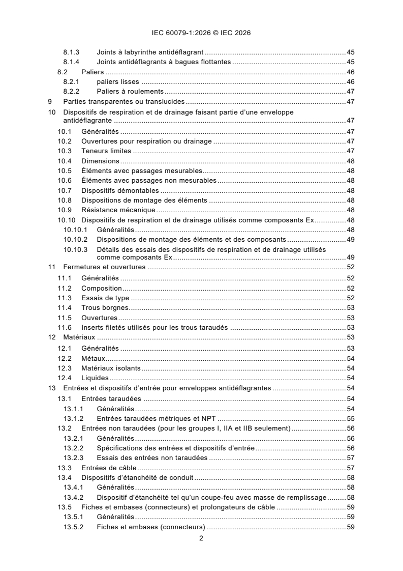
SOMMAIRE
AVANT-PROPOS . 9
1 Domaine d’application . 20
2 Références normatives . 20
3 Termes et définitions . 21
4 Niveau de protection . 24
4.1 Généralités . 24
4.2 Exigences qui s’appliquent au niveau de protection "da" . 24
4.3 Exigences qui s’appliquent au niveau de protection "db" . 25
4.4 Exigences qui s’appliquent au niveau de protection "dc" . 25
4.4.1 Généralités . 25
4.4.2 Composition . 25
4.4.3 Essais de type . 26
5 Joints antidéflagrants . 26
5.1 Exigences générales . 26
5.2 Joints non filetés antidéflagrants . 28
5.2.1 Longueur des joints antidéflagrants (L) . 28
5.2.2 Interstice (i) . 28
5.2.3 Joints à emboîtement antidéflagrants . 29
5.2.4 Joints cylindriques antidéflagrants . 30
5.2.5 Perçages dans les surfaces des joints antidéflagrants . 31
5.2.6 Joints coniques antidéflagrants . 33
5.2.7 Joints antidéflagrants à surfaces partiellement cylindriques . 33
5.2.8 Joints plans antidéflagrants pour atmosphères contenant de l’acétylène . 34
5.2.9 Joints dentelés antidéflagrants . 35
5.2.10 Joints à pas multiples antidéflagrants . 36
5.2.11 Autres joints antidéflagrants . 36
5.3 Joints filetés antidéflagrants . 40
5.4 Garnitures d’étanchéité (y compris les joints toriques) . 41
5.5 Appareils utilisant des capillaires . 43
6 Joints scellés . 43
6.1 Joints scellés (collés) . 43
6.1.1 Généralités . 43
6.1.2 Résistance mécanique . 43
6.1.3 Longueur des joints scellés . 44
6.2 Joints en verre fondu . 44
6.2.1 Généralités . 44
6.2.2 Longueur des joints en verre fondu . 44
6.3 Joints soudés ou brasés . 44
6.4 Joints enrobés . 44
6.4.1 Généralités . 44
6.4.2 Résistance mécanique . 45
7 Tiges de commande . 45
8 Exigences supplémentaires pour machines électriques . 45
8.1 Joints antidéflagrants des arbres . 45
8.1.1 Généralités . 45
8.1.2 Joints cylindriques antidéflagrants . 45
8.1.3 Joints à labyrinthe antidéflagrant . 45
8.1.4 Joints antidéflagrants à bagues flottantes . 45
8.2 Paliers . 46
8.2.1 paliers lisses . 46
8.2.2 Paliers à roulements . 47
9 Parties transparentes ou translucides . 47
10 Dispositifs de respiration et de drainage faisant partie d’une enveloppe
antidéflagrante . 47
10.1 Généralités . 47
10.2 Ouvertures pour respiration ou drainage . 47
10.3 Teneurs limites . 47
10.4 Dimensions . 48
10.5 Éléments avec passages mesurables. 48
10.6 Éléments avec passages non mesurables . 48
10.7 Dispositifs démontables . 48
10.8 Dispositions de montage des éléments . 48
10.9 Résistance mécanique . 48
10.10 Dispositifs de respiration et de drainage utilisés comme composants Ex . 48
10.10.1 Généralités . 48
10.10.2 Dispositions de montage des éléments et des composants . 49
10.10.3 Détails des essais des dispositifs de respiration et de drainage utilisés
comme composants Ex . 49
11 Fermetures et ouvertures . 52
11.1 Généralités . 52
11.2 Composition . 52
11.3 Essais de type . 52
11.4 Trous borgnes. 53
11.5 Ouvertures . 53
11.6 Inserts filetés utilisés pour les trous taraudés . 53
12 Matériaux . 53
12.1 Généralités . 53
12.2 Métaux . 54
12.3 Matériaux isolants . 54
12.4 Liquides . 54
13 Entrées et dispositifs d’entrée pour enveloppes antidéflagrantes . 54
13.1 Entrées taraudées . 54
13.1.1 Généralités . 54
13.1.2 Entrées taraudées métriques et NPT . 55
13.2 Entrées non taraudées (pour les groupes I, IIA et IIB seulement) . 56
13.2.1 Généralités . 56
13.2.2 Spécifications des entrées et dispositifs d’entrée . 56
13.2.3 Essais des entrées non taraudées . 57
13.3 Entrées de câble . 57
13.4 Dispositifs d’étanchéité de conduit . 58
13.4.1 Généralités . 58
13.4.2 Dispositif d’étanchéité tel qu’un coupe-feu avec masse de remplissage . 58
13.5 Fiches et embases (connecteurs) et prolongateurs de câble . 59
13.5.1 Généralités . 59
13.5.2 Fiches et embases (connecteurs) . 59
13.6 Traversées . 59
13.7 Dispositifs d’obturation . 60
13.7.1 Généralités . 60
13.7.2 Enveloppes avec entrées multiples . 60
13.7.3 Dispositifs d’obturation de composants Ex . 60
13.7.4 Documentation . 60
13.8 Adaptateurs filetés . 60
13.9 Entrées de fluide . 60
14 Piles et accumulateurs utilisés dans les enveloppes antidéflagrantes . 60
15 Vérification et essais . 61
16 Essais de type . 62
16.1 Généralités . 62
16.2 Essais de tenue à la pression de l’enveloppe . 62
16.2.1 Généralités . 62
16.2.2 Détermination de la pression d’explosion (pression de référence) . 63
16.2.3 Essai de surpression . 66
16.3 Essai de non-transmission d’une inflammation interne . 68
16.3.1 Généralités . 68
16.3.2 Appareils des groupes I, lIA et IIB . 70
16.3.3 Appareils du groupe IIC . 72
16.4 Essais des enveloppes antidéflagrantes avec dispositifs de respiration et de
drainage . 74
16.4.1 Généralités . 74
16.4.2 Essais de tenue à la pression de l’enveloppe. 74
16.4.3 Essais thermiques . 74
16.4.4 Essai de non-transmission d’une inflammation interne . 75
16.5 Distances dans l’air pour le niveau de protection "dc" . 76
16.5.1 Généralités . 76
16.5.2 Préparation des échantillons . 76
16.5.3 Conditions d’essai . 76
17 Épreuves individuelles de série . 77
17.1 Généralités . 77
17.2 Enveloppes ne comportant aucun joint soudé ou brasé . 79
17.3 Enveloppes comportant un joint soudé ou brasé . 79
17.4 Traversées non spécifiques d’une enveloppe antidéflagrante . 79
17.5 Critères d’acceptation . 79
17.6 Essais par lots . 79
18 Appareillage pour le groupe I . 80
18.1 Généralités . 80
18.2 Organes de mise hors tension. 80
18.3 Portes ou couvercles . 81
18.3.1 Portes ou couvercles à manœuvre rapide . 81
18.3.2 Porte ou couvercle à vis . 81
18.3.3 Portes ou couvercles vissés . 81
19 Douilles et culots de lampes . 81
19.1 Généralités . 81
19.2 Dispositif qui empêche l’autodesserrage des lampes . 81
19.3 Douilles et culots pour lampes à culots cylindriques . 81
19.4 Douilles pour lampes à culots à vis . 81
20 Enveloppes non métalliques ou parties non métalliques d’enveloppes . 82
20.1 Généralités . 82
20.2 Matériaux . 82
20.3 Exigences pour les essais de type . 82
20.4 Essai d’érosion par la flamme . 82
21 Marquage . 83
21.1 Généralités . 83
21.2 Avertissement et marquages . 83
21.3 Marquages informatifs . 83
22 Instructions . 84
Annexe A (normative) Exigences supplémentaires pour les éléments à ruban gaufré et
les éléments à grilles multiples des dispositifs de respiration et de drainage . 85
A.1 Matériau . 85
A.2 Dimensions des passages. 85
A.3 Essais de type . 85
Annexe B (normative) Exigences supplémentaires pour les éléments, avec passages
non mesurables pour les dispositifs de respiration et de drainage . 86
B.1 Éléments en métal fritté . 86
B.1.1 Matériau . 86
B.1.2 Dimension maximale de pore bulloscopique . 86
B.1.3 Documentation . 86
B.2 Éléments en fil métallique pressé . 86
B.2.1 Matériau . 86
B.2.2 Dimension maximale de pore bulloscopique . 86
B.2.3 Documentation . 87
B.3 Éléments en mousse métallique . 87
B.3.1 Matériau . 87
B.3.2 Dimension maximale de pore bulloscopique . 87
B.3.3 Documentation . 87
Annexe C (normative) Exigences supplémentaires pour les dispositifs d’entrée
antidéflagrants . 88
C.1 Généralités . 88
C.2 Exigences relatives à la construction . 88
C.2.1 Méthodes d’étanchéité . 88
C.2.2 Joints antidéflagrants . 90
C.2.3 Exigences de construction pour dispositifs d’obturation Ex . 91
C.2.4 Exigences de construction pour adaptateurs filetés Ex . 93
C.3 Essais de type . 93
C.3.1 Essai d’étanchéité . 93
C.3.2 Essai de résistance mécanique. 95
C.3.3 Essais de type pour dispositifs d’obturation Ex . 96
C.3.4 Essais de type pour adaptateurs filetés Ex . 96
Annexe D (normative) Enveloppes antidéflagrantes vides, comme composants Ex . 99
D.1 Généralités . 99
D.2 Remarques introductives . 99
D.3 Exigences relatives aux enveloppes de composants Ex . 99
D.3.1 Généralités . 99
D.3.2 Machines électriques . 99
D.3.3 Montage et emplacement des composants internes . 99
D.3.4 Perçage de trous . 100
D.3.5 Détermination de la pression d’explosion (pression de référence) . 100
D.3.6 Essai de surpression . 100
D.3.7 Épreuves individuelles de série . 100
D.3.8 Marquage . 100
D.3.9 Certificat d’enveloppe de composants Ex . 101
D.4 Utilisation du certificat d’enveloppe de composants Ex pour préparer un
certificat d’appareil Ex . 101
D.4.1 Procédure . 101
D.4.2 Application de la liste des limitations . 102
Annexe E (normative) Piles et accumulateurs utilisés dans les enveloppes
antidéflagrantes "db" . 103
E.1 Remarques introductives . 103
E.2 Systèmes électrochimiques acceptables . 103
E.3 Exigences générales pour les éléments ou batteries à l’intérieur
d’enveloppes antidéflagrantes . 106
E.3.1 Généralités . 106
E.3.2 Restrictions d’utilisation . 106
E.3.3 Marquage . 106
E.3.4 Montage . 106
E.3.5 Éléments en série . 107
E.3.6 Éléments en parallèle . 107
E.3.7 Éléments en série connectés en parallèle . 107
E.3.8 Aucune protection supplémentaire nécessaire . 107
E.4 Dispositions des dispositifs de sécurité . 108
E.4.1 Protection contre une température excessive et un courant de
décharge/charge excessif . 108
E.4.2 Protection contre l’inversion de polarité des éléments ou l’inversion de
charge par un autre élément dans la même batterie . 108
E.4.3 Prévention de charge par inadvertance d’une batterie par d’autres
sources de tension présentes dans l’enveloppe . 109
E.5 Recharge des accumulateurs à l’intérieur des enveloppes antidéflagrantes . 109
E.6 Caractéristiques assignées des composants de protection utilisés comme
dispositifs de sécurité . 110
Annexe F (informative) Propriétés mécaniques des vis et écrous . 111
Annexe G (normative) Exigences supplémentaires pour les enveloppes
antidéflagrantes avec un système de confinement . 113
G.1 Généralités . 113
G.2 Conditions de dégagement . 116
G.2.1 Pas de dégagement . 116
G.2.2 Dégagement limité de gaz ou vapeur . 116
G.2.3 Dégagement limité de liquide . 116
G.3 Exigences de conception pour le système de confinement . 116
G.3.1 Exigences générales de conception . 116
G.3.2 Système de confinement infaillible . 117
G.3.3 Système de confinement à dégagement limité . 117
G.4 Essais de type du système de confinement . 119
G.4.1 Essai de surpression . 119
G.4.2 Essai d’étanchéité . 119
G.4.3 Essai de mise à l’air libre à dégagement limité . 120
G.5 Épreuves individuelles de série pour les systèmes de confinement . 120
G.5.1 Systèmes de confinement infaillibles . 120
G.5.2 Systèmes de confinement à dégagement limité . 121
Annexe H (normative) Exigences pour les machines électriques utilisées avec des
convertisseurs . 122
H.1 Généralités . 122
H.2 Exigences de construction qui s’appliquent aux paliers . 122
H.3 Exigences relatives à la température . 122
Annexe I (informative) Recommandation visant à améliorer l’efficacité de la
détermination de la pression d’explosion . 123
I.1 Généralités . 123
I.2 Aspects pour améliorer la cohérence . 123
Bibliographie . 126
Figure 1 – Exemple de forme d’onde régulière . 23
Figure 2 – Exemple de forme d’onde irrégulière . 23
Figure 3 – Exemple de construction pour le contrôle indirect d’un joint plan
antidéflagrant du groupe I . 29
Figure 4 – Exemple de joint à emboîtement antidéflagrant . 30
Figure 5 – Exemples de joints cylindriques antidéflagrants . 30
Figure 6 – Orifices aux surfaces des joints plans antidéflagrants, exemple 1 . 31
Figure 7 – Orifices aux surfaces des joints plans antidéflagrants, exemple 2 . 31
Figure 8 – Orifices aux surfaces des joints plans antidéflagrants, exemple 3 . 32
Figure 9 – Orifices aux surfaces des joints à emboîtement antidéflagrants, exemple 1 . 32
Figure 10 – Orifices aux surfaces des joints à emboîtement antidéflagrants, exemple 2 . 33
Figure 11 – Orifices aux surfaces des joints à emboîtement antidéflagrants, exemple 3 . 33
Figure 12 – Exemple d’un joint antidéflagrant avec des surfaces partiellement
cylindriques . 34
Figure 13 – Exemple d’un joint plan antidéflagrant avec un interstice dynamiquement
augmenté. 35
Figure 14 – Exemple d’un joint dentelé antidéflagrant . 36
Figure 15 – Exemple d’un "autre joint antidéflagrant"·qui intègre des passages de
flamme non traités ailleurs dans le présent document . 38
Figure 16 – Représentation des exigences relatives aux garnitures d’étanchéité –
Exemple 1 . 41
Figure 17 – Représentation des exigences relatives aux garnitures d’étanchéité –
Exemple 2 . 41
Figure 18 – Représentation des exigences relatives aux garnitures d’étanchéité –
Exemple 3 . 42
Figure 19 – Représentation des exigences relatives aux garnitures d’étanchéité –
Exemple 4 . 42
Figure 20 – Représentation des exigences relatives aux garnitures d’étanchéité –
Exemple 5 . 42
Figure 21 – Représentation des exigences relatives aux garnitures d’étanchéité –
Exemple 6 . 42
Figure 22 – Représentation des exigences relatives aux garnitures d’étanchéité –
Exemple 7 . 42
Figure 23 – Exemple de joint cylindrique antidéflagrant pour arbre de machine
électrique tournante . 46
Figure 24 – Exemple de joint à labyrinthe antidéflagrant pour arbre de machine
électrique tournante . 46
Figure 25 – Exemple de joint antidéflagrant à bague flottante pour arbre de machine
électrique tournante . 46
Figure 26 – Joints antidéflagrants des traversées d’arbre de machines électriques . 46
Figure 27 – Dispositif d’essai de composants pour dispositifs de respiration et de
drainage . 50
Figure 28 – Exemple de représentation des informations exigées . 57
Figure C.1 – Exemples de dispositifs d’obturation pour les entrées non utilisées . 92
Figure C.2 – Dispositif pour les essais d’étanchéité des entrées de câble . 94
Figure E.1 – Montage de diodes pour trois éléments en série . 109
Figure E.2 – Mise en place de diodes antiretour pour la conformité à E.4.3 (troisième
exemple) . 109
Figure G.1 – Exemple d’enveloppe antidéflagrante avec système de confinement
infaillible . 114
Figure G.2 – Exemple d’enveloppe antidéflagrante avec un système de confinement à
dégagement limité sans dispositif limiteur de débit. 114
Figure G.3 – Exemple d’enveloppe antidéflagrante avec système de confinement à
dégagement limité avec dispositif limiteur de débit. 115
Figure G.4 – Exemple d’enveloppe antidéflagrante avec système de confinement à
dégagement limité (dégagement limité en fonctionnement normal) avec dispositif
limiteur de débit . 115
Tableau 1 – Nombre d’essais de non-transmission pour le niveau de protection "da" . 25
Tableau 2 – Longueur minimale de joints antidéflagrants et longueur maximale
interstices pour les enveloppes à utiliser dans les Groupes I, IIA et IIB . 39
Tableau 3 – Longueur minimale des joints antidéflagrants et interstices maximaux pour
les enveloppes à utiliser dans le groupe IIC . 39
Tableau 4 – Joints filetés cylindriques antidéflagrants. 40
Tableau 5 – Joints filetés coniques antidéflagrants . 41
Tableau 6 – Conditions de détermination de la température maximale de surface . 61
Tableau 7 – Facteurs d’essai pour les conditions ambiantes réduites . 64
Tableau 8 – Pressions relatives lorsque la détermination de la pression de référence
n’a pas été possible . 67
Tableau 9 – Réduction de la longueur d’un joint fileté antidéflagrant pour l’essai de
non-transmission . 69
Tableau 10 – Facteurs d’essai pour augmenter la pression ou l’interstice d’essai (i ). 69
E
Tableau 11 – Distance minimale de tout obstacle par rapport aux joints plans
antidéflagrants . 70
Tableau 12 – Mélanges gaz/air . 71
Tableau 13 – Pressions statiques . 78
Tableau 14 – Texte des avertissements ou marquages . 83
Tableau 15 – Texte des marquages informatifs . 84
Tableau C.1 – Valeurs de couple de serrage, filetages métriques . 97
Tableau C.2 – Valeurs de couple de serrage, filetages NPT . 98
Tableau E.1 – Piles acceptables . 104
Tableau E.2 – Accumulateurs acceptables . 105
Tableau F.1 – Propriétés mécaniques des vis et écrous . 111
Tableau G.1 – Paramètres d’essais de surpression . 119
COMMISSION ÉLECTROTECHNIQUE INTERNATIONALE
____________
Atmosphères explosives -
Partie 1: Protection des appareils par enveloppes antidéflagrantes "d"
AVANT-PROPOS
1) La Commission Électrotechnique Internationale (IEC) est une organisation mondiale de normalisation composée
de l’ensemble des comités électrotechniques nationaux (Comités nationaux de l’IEC). L’IEC a pour objet de
favoriser la coopération internationale pour toutes les questions de normalisation dans les domaines de
l’électricité et de l’électronique. À cet effet, l’IEC – entre autres activités – publie des Normes internationales,
des Spécifications techniques, des Rapports techniques, des Spécifications accessibles au public (PAS) et des
Guides (ci-après dénommés "Publication(s) de l’IEC"). Leur élaboration est confiée à des comités d’études, aux
travaux desquels tout Comité national intéressé par le sujet traité peut participer. Les organisations
internationales, gouvernementales et non gouvernementales, en liaison avec l’IEC, participent également aux
travaux. L’IEC collabore étroitement avec l’Organisation Internationale de Normalisation (ISO), selon des
conditions fixées par accord entre les deux organisations.
2) Les décisions ou accords officiels de l’IEC concernant les questions techniques représentent, dans la mesure du
possible, un accord international sur les sujets étudiés, étant donné que les Comités nationaux de l’IEC intéressés
sont représentés dans chaque comité d’études.
3) Les Publications de l’IEC se présentent sous la forme de recommandations internationales et sont agréées
comme telles par les Comités nationaux de l’IEC. Tous les efforts raisonnables sont entrepris afin que l’IEC
s’assure de l’exactitude du contenu technique de ses publications; l’IEC ne peut pas être tenue responsable de
l’éventuelle mauvaise utilisation ou interprétation qui en est faite par un quelconque utilisateur final.
4) Dans le but d’encourager l’uniformité internationale, les Comités nationaux de l’IEC s’engagent, dans toute la
mesure possible, à appliquer de façon transparente les Publications de l’IEC dans leurs publications nationales
et régionales. Toutes divergences entre toutes Publications de l’IEC et toutes publications nationales ou
régionales correspondantes doivent être indiquées en termes clairs dans ces dernières.
5) L’IEC elle-même ne fournit aucune attestation de conformité. Des organismes de certification indépendants
fournissent des services d’évaluation de conformité et, dans certains secteurs, accèdent aux marques de
conformité de l’IEC. L’IEC n’est responsable d’aucun des services effectués par les organismes de certification
indépendants.
6) Tous les utilisateurs doivent s’assurer qu’ils sont en possession de la dernière édition de cette publication.
7) Aucune responsabilité ne doit être imputée à l’IEC, à ses administrateurs, employés, auxiliaires ou mandataires,
y compris s
...