


IEC 62642-2-5:2010
(Main)Alarm systems - Intrusion and hold-up systems - Part 2-5: Intrusion detectors - Combined passive infrared / Ultrasonic detectors
General Information
- Abstract
IEC 62642-2-5:2010 is for combined passive infrared and ultrasonic detectors installed in buildings and provides for security grades 1 to 4 (see IEC 62642-1), specific or non-specific wired or wire-free detectors, and uses environmental classes I to IV (see IEC 62599-1).
- Status
- Withdrawn
- Publication Date
- 13-Dec-2010
- Withdrawal Date
- 05-Nov-2023
- Technical Committee
- TC 79 - Alarm and electronic security systems
- Current Stage
- WPUB - Publication withdrawn
- Start Date
- 06-Nov-2023
- Completion Date
- 06-Nov-2023

Get Certified
Connect with accredited certification bodies for this standard

NSF International
Global independent organization facilitating standards development and certification.

CIS Institut d.o.o.
Personal Protective Equipment (PPE) certification body. Notified Body NB-2890 for EU Regulation 2016/425 PPE.

Kiwa BDA Testing
Building and construction product certification.
Sponsored listings
Frequently Asked Questions
IEC 62642-2-5:2010 is a standard published by the International Electrotechnical Commission (IEC). Its full title is "Alarm systems - Intrusion and hold-up systems - Part 2-5: Intrusion detectors - Combined passive infrared / Ultrasonic detectors". This standard covers: IEC 62642-2-5:2010 is for combined passive infrared and ultrasonic detectors installed in buildings and provides for security grades 1 to 4 (see IEC 62642-1), specific or non-specific wired or wire-free detectors, and uses environmental classes I to IV (see IEC 62599-1).
IEC 62642-2-5:2010 is for combined passive infrared and ultrasonic detectors installed in buildings and provides for security grades 1 to 4 (see IEC 62642-1), specific or non-specific wired or wire-free detectors, and uses environmental classes I to IV (see IEC 62599-1).
IEC 62642-2-5:2010 is classified under the following ICS (International Classification for Standards) categories: 13.320 - Alarm and warning systems. The ICS classification helps identify the subject area and facilitates finding related standards.
IEC 62642-2-5:2010 is available in PDF format for immediate download after purchase. The document can be added to your cart and obtained through the secure checkout process. Digital delivery ensures instant access to the complete standard document.
Standards Content (Sample)
IEC 62642-2-5 ®
Edition 1.0 2010-12
INTERNATIONAL
STANDARD
NORME
INTERNATIONALE
colour
inside
Alarm systems – Intrusion and hold-up systems –
Part 2-5: Intrusion detectors – Combined passive infrared / Ultrasonic detectors
Systèmes d'alarme – Systèmes d'alarme contre l’intrusion et les hold-up –
Partie 2-5: Détecteurs d'intrusion – Détecteurs combinés à infrarouges passifs et
à ultrasons
All rights reserved. Unless otherwise specified, no part of this publication may be reproduced or utilized in any form or by
any means, electronic or mechanical, including photocopying and microfilm, without permission in writing from either IEC or
IEC's member National Committee in the country of the requester.
If you have any questions about IEC copyright or have an enquiry about obtaining additional rights to this publication,
please contact the address below or your local IEC member National Committee for further information.
Droits de reproduction réservés. Sauf indication contraire, aucune partie de cette publication ne peut être reproduite
ni utilisée sous quelque forme que ce soit et par aucun procédé, électronique ou mécanique, y compris la photocopie
et les microfilms, sans l'accord écrit de la CEI ou du Comité national de la CEI du pays du demandeur.
Si vous avez des questions sur le copyright de la CEI ou si vous désirez obtenir des droits supplémentaires sur cette
publication, utilisez les coordonnées ci-après ou contactez le Comité national de la CEI de votre pays de résidence.
IEC Central Office
3, rue de Varembé
CH-1211 Geneva 20
Switzerland
Email: inmail@iec.ch
Web: www.iec.ch
About the IEC
The International Electrotechnical Commission (IEC) is the leading global organization that prepares and publishes
International Standards for all electrical, electronic and related technologies.
About IEC publications
The technical content of IEC publications is kept under constant review by the IEC. Please make sure that you have the
latest edition, a corrigenda or an amendment might have been published.
§ Catalogue of IEC publications: www.iec.ch/searchpub
The IEC on-line Catalogue enables you to search by a variety of criteria (reference number, text, technical committee,…).
It also gives information on projects, withdrawn and replaced publications.
§ IEC Just Published: www.iec.ch/online_news/justpub
Stay up to date on all new IEC publications. Just Published details twice a month all new publications released. Available
on-line and also by email.
§ Electropedia: www.electropedia.org
The world's leading online dictionary of electronic and electrical terms containing more than 20 000 terms and definitions
in English and French, with equivalent terms in additional languages. Also known as the International Electrotechnical
Vocabulary online.
§ Customer Service Centre: www.iec.ch/webstore/custserv
If you wish to give us your feedback on this publication or need further assistance, please visit the Customer Service
Centre FAQ or contact us:
Email: csc@iec.ch
Tel.: +41 22 919 02 11
Fax: +41 22 919 03 00
A propos de la CEI
La Commission Electrotechnique Internationale (CEI) est la première organisation mondiale qui élabore et publie des
normes internationales pour tout ce qui a trait à l'électricité, à l'électronique et aux technologies apparentées.
A propos des publications CEI
Le contenu technique des publications de la CEI est constamment revu. Veuillez vous assurer que vous possédez
l’édition la plus récente, un corrigendum ou amendement peut avoir été publié.
§ Catalogue des publications de la CEI: www.iec.ch/searchpub/cur_fut-f.htm
Le Catalogue en-ligne de la CEI vous permet d’effectuer des recherches en utilisant différents critères (numéro de référence,
texte, comité d’études,…). Il donne aussi des informations sur les projets et les publications retirées ou remplacées.
§ Just Published CEI: www.iec.ch/online_news/justpub
Restez informé sur les nouvelles publications de la CEI. Just Published détaille deux fois par mois les nouvelles
publications parues. Disponible en-ligne et aussi par email.
§ Electropedia: www.electropedia.org
Le premier dictionnaire en ligne au monde de termes électroniques et électriques. Il contient plus de 20 000 termes et
définitions en anglais et en français, ainsi que les termes équivalents dans les langues additionnelles. Egalement appelé
Vocabulaire Electrotechnique International en ligne.
§ Service Clients: www.iec.ch/webstore/custserv/custserv_entry-f.htm
Si vous désirez nous donner des commentaires sur cette publication ou si vous avez des questions, visitez le FAQ du
Service clients ou contactez-nous:
Email: csc@iec.ch
Tél.: +41 22 919 02 11
Fax: +41 22 919 03 00
IEC 62642-2-5 ®
Edition 1.0 2010-12
INTERNATIONAL
STANDARD
NORME
INTERNATIONALE
colour
inside
Alarm systems – Intrusion and hold-up systems –
Part 2-5: Intrusion detectors – Combined passive infrared / Ultrasonic detectors
Systèmes d'alarme – Systèmes d'alarme contre l’intrusion et les hold-up –
Partie 2-5: Détecteurs d'intrusion – Détecteurs combinés à infrarouges passifs
et à ultrasons
INTERNATIONAL
ELECTROTECHNICAL
COMMISSION
COMMISSION
ELECTROTECHNIQUE
PRICE CODE
INTERNATIONALE
X
CODE PRIX
ICS 13.320 ISBN 978-2-88912-306-3
– 2 – 62642-2-5 Ó IEC:2010
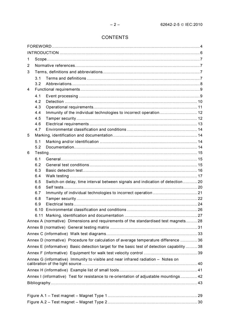
CONTENTS
FOREW ORD . 4
INTRODUCTION . 6
1 Sc o pe . 7
2 Normative references . 7
3 Terms, definitions and abbreviations. 7
3.1 Terms and definitions . 7
3.2 Abbrev iations. 8
4 Functional requirements . 9
4.1 Event processing . 9
4.2 Detection . 10
4.3 Operational requirements . 11
4.4 Immunity of the individual technologies to incorrect operation . 12
4.5 Tamper security . 12
4.6 Electrical requirements . 13
4.7 Environmental classification and conditions . 14
5 Marking, identification and documentation . 14
5.1 Marking and/or identification . 14
5.2 Documentation. 14
6 Testing . 15
6.1 General . 15
6.2 General test conditions . 15
6.3 Basic detection test . 16
6.4 Walk testing . 17
6.5 Switch-on delay, time interval between signals and indication of detection . 20
6.6 Self tests . 20
6.7 Immunity of individual technologies to incorrect operation . 21
6.8 Tamper security . 22
6.9 Electrical tests . 24
6.10 Environmental classification and conditions . 26
6.11 Marking, identification and documentation . 27
Annex A (normative) Dimensions and requirements of the standardised test magnets. 28
Annex B (normative) General testing matrix . 31
Annex C (informative) Walk test diagrams . 33
Annex D (normative) Procedure for calculation of average temperature difference . 36
Annex E (informative) Basic detection target for the basic test of detection capability . 38
Annex F (informative) Equipment for walk test velocity control . 39
Annex G (informative) Immunity to visible and near infrared radiation – Notes on
calibration of the light source . 40
Annex H (informative) Example list of small tools . 41
Annex I (informative) Test for resistance to re-orientation of adjustable mountings . 42
Bibliography . 43
Figure A.1 – Test magnet – Magnet Type 1 . 29
Figure A.2 – Test magnet – Magnet Type 2 . 30
62642-2-5 Ó IEC:2010 – 3 –
Figure C.1 – Detection across the boundary . 33
Figure C.2 – Detection within the boundary . 33
Figure C.3 – High velocity and intermittent movement . 34
Figure C.4 – Close-in detection . 34
Figure C.5 – Significant range reduction . 35
Figure I.1 – Re-orientation test . 42
Table 1 – Events to be processed by grade . 9
Table 2 – Generation of signals or messages . 9
Table 3 – General walk test velocity and attitude requirements. 10
Table 4 – Tamper security requirements . 13
Table 5 – Grade dependencies for electrical requirements . 13
Table 6 – Range of materials for masking tests . 24
Table 7 – Operational tests. 27
Table 8 – Endurance tests . 27
Table D.1 – Measurement and calculation of the real average temperature difference
between the SWT and the background . 36
– 4 – 62642-2-5 Ó IEC:2010
INTERNATIONAL ELECTROTECHNICAL COMMISSION
____________
ALARM SYSTEMS –
INTRUSION AND HOLD-UP SYSTEMS –
Part 2-5: Intrusion detectors –
Combined passive infrared / Ultrasonic detectors
FOREWORD
1) The International Electrotechnical Commission (IEC) is a worldwide organization for standardization comprising
all national electrotechnical committees (IEC National Committees). The object of IEC is to promote
international co-operation on all questions concerning standardization in the electrical and electronic fields. To
this end and in addition to other activities, IEC publishes International Standards, Technical Specifications,
Technical Reports, Publicly Available Specifications (PAS) and Guides (hereafter referred to as “IEC
Publication(s)”). Their preparation is entrusted to technical committees; any IEC National Committee interested
in the subject dealt with may participate in this preparatory work. International, governmental and non-
governmental organizations liaising with the IEC also participate in this preparation. IEC collaborates closely
with the International Organization for Standardization (ISO) in accordance with conditions determined by
agreement between the two organizations.
2) The formal decisions or agreements of IEC on technical matters express, as nearly as possible, an international
consensus of opinion on the relevant subjects since each technical committee has representation from all
interested IEC National Committees.
3) IEC Publications have the form of recommendations for international use and are accepted by IEC National
Committees in that sense. While all reasonable efforts are made to ensure that the technical content of IEC
Publications is accurate, IEC cannot be held responsible for the way in which they are used or for any
misinterpretation by any end user.
4) In order to promote international uniformity, IEC National Committees undertake to apply IEC Publications
transparently to the maximum extent possible in their national and regional publications. Any divergence
between any IEC Publication and the corresponding national or regional publication shall be clearly indicated in
the latter.
5) IEC itself does not provide any attestation of conformity. Independent certification bodies provide conformity
assessment services and, in some areas, access to IEC marks of conformity. IEC is not responsible for any
services carried out by independent certification bodies.
6) All users should ensure that they have the latest edition of this publication.
7) No liability shall attach to IEC or its directors, employees, servants or agents including individual experts and
members of its technical committees and IEC National Committees for any personal injury, property damage or
other damage of any nature whatsoever, whether direct or indirect, or for costs (including legal fees) and
expenses arising out of the publication, use of, or reliance upon, this IEC Publication or any other IEC
Publications.
8) Attention is drawn to the Normative references cited in this publication. Use of the referenced publications is
indispensable for the correct application of this publication.
9) Attention is drawn to the possibility that some of the elements of this IEC Publication may be the subject of
patent rights. IEC shall not be held responsible for identifying any or all such patent rights.
International Standard IEC 62642-2-5 has been prepared by IEC technical committee 79:
Alarm and electronic security systems.
This standard is based on EN 50131-2-5 (2008).
The text of this standard is based on the following documents:
FDIS Report on voting
79/324/FDIS 79/330/RVD
Full information on the voting for the approval of this standard can be found in the report on
voting indicated in the above table.
This publication has been drafted in accordance with the ISO/IEC Directives, Part 2.
62642-2-5 Ó IEC:2010 – 5 –
A list of all parts of the IEC 62642 series can be found, under the general title Alarm systems
– Intrusion and hold-up systems, on the IEC website.
The committee has decided that the contents of this publication will remain unchanged until
the stability result date indicated on the IEC web site under "http://webstore.iec.ch" in the data
related to the specific publication. At this date, the publication will be
reconfirmed,
withdrawn,
replaced by a revised edition, or
amended.
IMPORTANT – The “colour inside” logo on the cover page of this publication indicates
that it contains colours which are considered to be useful for the correct understanding
of its contents. Users should therefore print this publication using a colour printer.
– 6 – 62642-2-5 Ó IEC:2010
INTRODUCTION
This part 2-5 of the IEC 62642 series of standards gives requirements for combined passive
infrared and ultrasonic detectors used in intrusion and hold-up alarm systems. The other parts
of this series of standards are as follows:
Part 1 System requirements
Part 2-2 Intrusion detectors – Passive infrared detectors
Part 2-3 Intrusion detectors – Microwave detectors
Part 2-4 Intrusion detectors – Combined passive infrared / Microwave detectors
Part 2-5 Intrusion detectors – Combined passive infrared / Ultrasonic detectors
Part 2-6 Intrusion detectors – Opening contacts (magnetic)
Part 2-71 Intrusion detectors – Glass break detectors – Acoustic
Part 2-72 Intrusion detectors – Glass break detectors – Passive
Part 2-73 Intrusion detectors – Glass break detectors – Active
Part 3 Control and indicating equipment
Part 4 Warning devices
Part 5-3 Requirements for interconnections equipment using radio frequency
techniques
Part 6 Power supplies
Part 7 Application guidelines
Part 8 Security fog devices/systems
This standard is for combined passive infrared and ultrasonic detectors (to be referred to as
the detector) used as part of intrusion alarm systems installed in buildings. It includes four
security grades and four environmental classes.
The purpose of a detector is to detect the broad spectrum infrared radiation emitted by an
intruder and, at the same time, to emit ultrasonic radiation over the area being protected, and
analyse signals that are returned, to provide the necessary range of signals or messages to
be used by the rest of the intrusion alarm system.
The number and scope of these signals or messages will be more comprehensive for systems
that are specified at the higher grades.
This standard is only concerned with the requirements and tests for the detector. Other types
of detector are covered by other documents identified as IEC 62642-2 series.
62642-2-5 Ó IEC:2010 – 7 –
ALARM SYSTEMS –
INTRUSION AND HOLD-UP SYSTEMS –
Part 2-5: Intrusion detectors –
Combined passive infrared / Ultrasonic detectors
1 Scope
This part of the IEC 62642 is for combined passive infrared and ultrasonic detectors installed
in buildings and provides for security grades 1 to 4 (see IEC 62642-1), specific or non-specific
wired or wire-free detectors, and uses environmental classes I to IV (see IEC 62599-1). This
standard does not include requirements for combined passive infra red and ultrasonic
detectors intended for use outdoors.
A detector should fulfil all the requirements of the specified grade.
Functions additional to the mandatory functions specified in this standard may be included in
the detector, providing they do not influence the correct operation of the mandatory functions.
The International Standard does not apply to system interconnections.
2 Normative references
The following referenced documents are indispensable for the application of this document.
For dated references, only the edition cited applies. For undated references, the latest edition
of the referenced document (including any amendments) applies.
IEC 60068-1:1988, Environmental testing – Part 1: General and guidance
IEC 60068-2-52, Environmental testing – Part 2-52: Tests – Test Kb: Salt mist, cyclic (sodium
chloride solution)
IEC 62599-1, Alarm systems – Part 1: Environmental test methods
IEC 62599-2, Alarm systems – Part 2: Electromagnetic compatibility – Immunity requirements
for components of fire and security alarm systems
IEC 62642-1, Alarm systems – Intrusion and hold-up systems – Part 1: System requirements
IEC 62642-6, Alarm systems – Intrusion and hold-up systems – Part 6: Power supplies
3 Terms, definitions and abbreviations
3.1 Terms and definitions
For the purposes of this document, the terms and definitions given in IEC 62642-1, as well as
the following apply.
– 8 – 62642-2-5 Ó IEC:2010
3.1.1
basic detection target
heat source and/or ultrasonic reflector designed to verify the operation of a detector
3.1.2
combined passive infrared and ultrasonic detector
detector of the broad-spectrum infrared radiation emitted by a human being, with an active
ultrasonic emitter and receiver installed in the same housing
3.1.3
incorrect operation
physical condition that causes an inappropriate signal or message from a detector
3.1.4
masking
interference with the detector input capability by the introduction of a physical barrier such as
metal, plastics, paper or sprayed paints or lacquers in close proximity to the detector
3.1.5
simulated walk test target
non-human or synthetic heat source or ultrasonic reflector designed to simulate the standard
walk test target
3.1.6
standard walk test target
human being of standard weight and height clothed in close fitting clothing appropriate to the
simulation of an intruder
3.1.7
walk test
operational test during which a detector is stimulated by the standard walk test target in a
controlled environment
3.1.8
walk test attitude, crawling
crawling attitude that consists of the standard walk test target moving with hands and knees in
contact with the floor
3.1.9
walk test attitude, upright
upright attitude that consists of the standard walk test target standing and walking with arms
held at the sides of the body. The standard walk test target begins and ends a traverse with
feet together
3.2 Abbreviations
For the purposes of this document, the abbreviations given in IEC 62642-1, as well as the
following apply.
HDPE high density polyethylene
PIR passive infrared
EMC electromagnetic compatibility
SWT standard walk-test target
BDT basic detection target
62642-2-5 Ó IEC:2010 – 9 –
FOV field of view
4 Functional requirements
4.1 Event processing
Detectors shall process the events shown in Table 1. Detectors shall generate signals or
messages as shown in Table 2.
Table 1 – Events to be processed by grade
Event Grade
1 2 3 4
Intrusion detection M M M M
Tamper detection Op M M M
Masking detection Op Op M M
Significant reduction of range Op Op Op M
Low supply voltage Op Op M M
Total loss of power supply Op M M M
Local self test Op Op M M
Remote self test Op Op Op M
Key
M = Mandatory
Op = Optional
Table 2 – Generation of signals or messages
Event Signals or messages
Intrusion Tamper Fault
No event NP NP NP
Intrusion M NP NP
Tamper NP M NP
a
Masking M Op M
a
Significant reduction of range M Op M
Low supply voltage Op Op M
b
Total loss of power supply
M Op Op
Local self test pass NP NP NP
Local self test fail NP NP M
Remote self test pass M NP NP
Remote self test fail NP NP M
Key
M = Mandatory
NP = Not Permitted
Op = Optional
NOTE 1 This permits two methods of signalling a masking or reduction of range event:
either by the intrusion signal and fault signal, or by a dedicated masking or reduction of
range signal or message. Use of the intrusion signal and fault signal is preferable, as this
requires fewer connections between CIE and detector. If multiple events overlap there will
be some signal combinations that may be ambiguous. To overcome this ambiguity it is
suggested that detectors should not signal ‘intrusion‘ and ‘fault‘ at the same time except
to indicate masking. This implies that the detector should prioritise signals, e.g. 1
Intrusion, 2 Fault, 3 Masking.
– 10 – 62642-2-5 Ó IEC:2010
NOTE 2 When, in Table 1, an event may optionally generate signals or messages, they
are as shown in this table.
NOTE 3 It is accepted that a bus system may send out dedicated signals or messages
and does not necessarily have to follow the mapping of Table 2 provided that all of the
required events are signalled.
a
An independent signal or message may be provided instead.
b
Alternatively total loss of power supply shall be determined by loss of communication
with the detector.
4.2 Detection
4.2.1 Detection performance
The detector shall generate an intrusion signal or message when the standard or simulated
walk-test target moves at velocities and attitudes specified in Table 3. For detection across
the boundary, the walk-test distance shall be 1,5 m either side of the boundary. For detection
within the boundary, the walk-test distance shall be 3,0 m.
Table 3 – General walk test velocity and attitude requirements
Test Grade 1 Grade 2 Grade 3 Grade 4
Detection across the boundary Required Required Required Required
–1 –1 –1 –1
Velocity 1,0 ms 1,0 ms 1,0 ms 1,0 ms
Attitude Upright Upright Upright Upright
Detection within the boundary Required Required Required Required
–1 –1 –1 –1
Velocity 0,3 ms 0,3 ms 0,2 ms 0,1 ms
Attitude Upright Upright Upright Upright
Detection at high velocity Not required Required Required Required
–1 –1 –1
Velocity N/A 2,0 ms 2,5 ms 3,0 ms
Attitude N/A Upright Upright Upright
Close-in detection performance Required Required Required Required
Distance 2,0 m 2,0 m 0,5 m 0,5 m
–1 –1 –1 –1
Velocity 0,5 ms 0,4 ms 0,3 ms 0,2 ms
Attitude Upright Upright Crawling Crawling
Intermittent movement detection Not required Not required Required Required
a
performance
–1 –1
Velocity N/A N/A 1,0 ms 1,0 ms
Attitude N/A N/A Upright Upright
b
Significant reduction of specified range Not required Not required Not required Required
–1
Velocity N/A N/A N/A 1,0 ms
Attitude N/A N/A N/A Upright
a
For grades 3 and 4 detectors, the intermittent movement shall consist of the SWT walking 1 m at a velocity of
–1
1,0 ms then pausing for 5 s before continuing. The sequence shall be maintained until the SWT has traversed
through the entire detection area. This constitutes one walk test. The test shall be repeated in each of the
directions shown in Figure C.3.
b
The means to detect a significant reduction in range may be met either by detectors having the appropriate
function (4.2.3) or by suitable system design. Two or more devices (e.g. a detector in conjunction with a
camera, active transmitter or additional detector), may cooperate and interconnect with the system to provide
means to detect a significant reduction of range.
62642-2-5 Ó IEC:2010 – 11 –
4.2.2 Indication of detection
An indicator shall be provided at the detector to indicate when an intrusion signal or message
has been generated. At grades 1 and 2 this indicator shall be capable of being enabled and
disabled either remotely at Access Level 2 and/or locally after removal of a cover which
provides tamper detection as described in Tables 1 and 4. At grades 3 and 4 this indicator
shall be capable of being enabled and disabled remotely at Access Level 2.
4.2.3 Significant reduction of range
Grade 4 detectors shall detect significant reduction of range or coverage area due, for
example, to deliberate or accidental introduction of objects or obstructions into the coverage
area.
Range reduction along the principal axis of detection of more than 50 % shall generate a
signal or message within 180 s, according to the requirements of Table 2 and Table 3.
If additional equipment is required to detect significant reduction of range, reference shall be
made to this equipment and its operation in the manufacturer’s documentation.
4.3 Operational requirements
4.3.1 Time interval between intrusion signals or messages
Detectors using wired interconnections shall be able to provide an intrusion signal or message
not more than 15 s after the end of the preceding intrusion signal or message.
Detectors using wirefree interconnections shall be able to provide an intrusion signal or
message after the end of the preceding intrusion signal or message within the following times:
Grade 1 300 s;
Grade 2 180 s;
Grade 3 30 s;
Grade 4 15 s.
4.3.2 Switch on delay
The detector shall meet all functional requirements within 180 s of the power supply reaching
its nominal voltage as specified by the manufacturer.
4.3.3 Self tests
4.3.3.1 Local self test
The detector shall automatically test itself at least once every 24 h according to the
requirements of Tables 1 and 2. If normal operation of the detector is inhibited during a local
self-test, the detector inhibition time shall be limited to a maximum of 30 s in any period of
2 h.
4.3.3.2 Remote self test
A detector shall process remote self tests and generate signals or messages in accordance
with Tables 1 and 2 within 10 s of the remote self test signal being received, and shall return
to normal operation within 30 s of the remote test signal being received.
– 12 – 62642-2-5 Ó IEC:2010
4.4 Immunity of the individual technologies to incorrect operation
The detector shall be considered to have sufficient immunity to incorrect operation if the
following requirements have been met. No intrusion signal or message shall be generated
during the tests.
4.4.1 Immunity to air flow
The PIR component of the detector shall not generate any signal or message when air is
blown over the face of the detector.
4.4.2 Immunity to visible and near infrared radiation
The PIR component of the detector shall not generate any signal or message when a car
headlamp is swept across the front window or lens through two panes of glass.
4.4.3 Immunity to ultrasonic signal interference by extraneous sound sources
The ultrasonic component of the combined detector shall not generate an intrusion signal or
message due to the operation of a sound source mounted nearby.
4.5 Tamper security
Tamper security requirements for each grade of detector are shown in Table 4.
4.5.1 Resistance to and detection of unauthorised access to components and means
of adjustment
All components, means of adjustment and access to mounting screws, which, when interfered
with, could adversely affect the operation of the detector, shall be located within the detector
housing. Such access shall require the use of an appropriate tool and depending on the grade
as specified in Table 4 shall generate a tamper signal or message before access can be
gained.
It shall not be possible to gain such access without generating a tamper signal or message or
causing visible damage.
4.5.2 Detection of removal from the mounting surface
A tamper signal or message shall be generated if the detector is removed from its mounting
surface, in accordance with Table 4.
4.5.3 Resistance to, or detection of, re-orientation
When the torque given in Table 4 is applied to the detector it shall not rotate more than 5°.
Alternatively, when the torque given in Table 4 is applied, a tamper signal or message shall
be generated before the detector has rotated by 5°.
4.5.4 Immunity to magnetic field interference
It shall not be possible to inhibit any signals or messages with a magnet of grade dependence
according to Table 4. The magnet types shall be as described in Annex A.
4.5.5 Detection of masking
Means shall be provided to detect inhibition of the operation of the detector by masking
according to the requirements of Table 4.
The maximum response time for the masking detection device shall be 180 s. Masking shall
be signalled according to the requirements of Table 2. The signals or messages shall remain
62642-2-5 Ó IEC:2010 – 13 –
for at least as long as the masking condition is present. A masking signal or message shall
not be reset while the masking condition is still present. Alternatively the masking signal or
message shall be generated again within 180 s of being reset if the masking condition is still
present.
NOTE From a system design point of view it would be preferable for masked detectors to automatically reset after
the masking condition is removed.
–1
No masking signal or message shall be generated by normal human movement at 1 ms at a
distance equal to or greater than 1 m.
For detectors where detection of masking may be remotely disabled, the detection of masking
shall operate when the I&HAS is unset; it is not required to operate when the I&HAS is set.
Table 4 – Tamper security requirements
Requirement Grade 1 Grade 2 Grade 3 Grade 4
Resistance to access to the inside of the Required Required Required Required
detector
Detection of access to the inside of the detector Not Required Required Required Required
Removal from the mounting surface wired Not required Not Required Required Required
detectors
Removal from the mounting surface wirefree Not required Required Required Required
detectors
Resistance to, or detection of, re-orientation - for Not required Required Required Required
detectors mounted on brackets only
Applied torque 2 Nm 5 Nm 10 Nm
Magnetic field immunity Not required Required Required Required
Magnet type defined in Annex A Type 1 Type 2 Type 2
Masking detection Not required Not required Required Required
4.6 Electrical requirements
4.6.1 Grade dependencies
The grade dependencies appear in Table 5. These requirements do not apply to detectors
having Type C power supplies. For these detectors, refer to IEC 62642-6.
Table 5 – Grade dependencies for electrical requirements
Test Grade 1 Grade 2 Grade 3 Grade 4
Detector current consumption Required Required Required Required
Input voltage range Required Required Required Required
Slow input voltage rise Not required Required Required Required
Input voltage ripple Not required Required Required Required
Input voltage step change Not required Required Required Required
4.6.2 Detector current consumption
The detector’s quiescent and maximum current consumption shall not exceed the figures
claimed by the manufacturer at the nominal input voltage.
– 14 – 62642-2-5 Ó IEC:2010
4.6.3 Slow input voltage change and voltage range limits
The detector shall meet all functional requirements when the input voltage lies between
± 25 % of the nominal value, or between the manufacturer’s stated values if greater. When the
supply voltage is raised slowly, the detector shall function normally at the specified range
limits.
4.6.4 Input voltage ripple
The detector shall meet all functional requirements during the sinusoidal variation of the input
voltage by ± 10 % of nominal, at a frequency of 100 Hz.
4.6.5 Input voltage step change
No signals or messages shall be caused by a step in the input voltage between nominal and
maximum and between nominal and minimum.
4.7 Environmental classification and conditions
4.7.1 Environmental classification
The environmental classification is described in IEC 62642-1 and shall be specified by the
manufacturer.
4.7.2 Immunity to environmental conditions
Detectors shall meet the requirements of the environmental tests described in Tables 7 and 8.
These tests shall be performed in accordance with IEC 62599-1 and IEC 62642-2.
Unless specified otherwise for operational tests, the detector shall not generate unintentional
intrusion, tamper, fault or other signals or messages when subjected to the specified range of
environmental conditions.
Impact tests shall not be carried out on delicate detector components such as LEDs, optical
windows or lenses.
For endurance tests, the detector shall continue to meet the requirements of this standard
after being subjected to the specified range of environmental conditions.
5 Marking, identification and documentation
5.1 Marking and/or identification
Marking and/or identification shall be applied to the product in accordance with the
requirements of IEC 62642-1.
5.2 Documentation
The product shall be accompanied with clear and concise documentation conforming to the
main systems document IEC 62642-1. The documentation shall additionally state
a) a list of all options, functions, inputs, signals or messages, indications and their relevant
characteristics;
b) the manufacturer’s diagram of the detector and its claimed detection boundary showing
top and side elevations at 2,0 m mounting height or at a height specified by the
manufacturer, superimposed upon a scaled 2 m squared grid. The size of the grid shall be
directly related to the size of the claimed detection boundary;
62642-2-5 Ó IEC:2010 – 15 –
c) the recommended mounting height, and the effect of changes to it on the claimed
detection boundary;
d) the effect of adjustable controls on the detector’s performance or on the claimed detection
boundary including at least the minimum and maximum settings;
e) any disallowed field adjustable control settings or combinations of these;
f) any specific settings needed to meet the requirements of this International Standard at the
claimed grade;
g) where alignment adjustments are provided, these shall be labelled as to their function;
h) a warning to the user not to obscure partially or completely the detector’s field of view;
i) the manufacturer’s quoted nominal operating voltage, and the maximum and quiescent
current consumption at that voltage;
j) any special requirements needed for detecting a significant reduction in range, where
provided.
6 Testing
6.1 General
The tests are intended to be primarily concerned with verifying the correct operation of the
detector to the specification provided by the manufacturer. All the test parameters specified
shall carry a general tolerance of ± 10 % unless otherwise stated. A list of tests appears as a
general test matrix in Annex B.
6.2 General test conditions
6.2.1 Standard conditions for testing
The general atmospheric conditions in the measurement and tests laboratory shall be those
specified in IEC 60068-1:1988, 5.3.1, unless stated otherwise.
Temperature 15 °C to 35 °C
Relative humidity 25 % RH to 75 % RH
Air pressure 86 kPa to 106 kPa
6.2.2 General detection testing environment and procedures
Manufacturer’s documented instructions regarding mounting and operation shall be read and
applied to all tests.
6.2.3 Testing environment
The detection tests require an enclosed, unobstructed and draught-free area that enables
testing of the manufacturer’s claimed coverage pattern. The test area shall be large enough
so as not to significantly affect the ultrasonic coverage pattern due to reflections.
The test area walls and floor shall have a recommended emissivity of at least 80 % between
8 mm and 14 mm wavelength, at least directly behind the SWT.
The temperature of the background surface immediately behind the SWT shall be in the range
15 °C to 25 °C, and shall be horizontally uniform over that area to ± 2 °C. Over the whole
background area, it shall be measured at ten points spread evenly throughout the coverage
pattern. The average background temperature is the linear average of the ten points.
The default mounting height shall be 2,0 m unless otherwise specified by the manufacturer.
– 16 – 62642-2-5 Ó IEC:2010
Annex C provides example diagrams for the range of walk tests for one format of detection
pattern. Many others are possible.
6.2.4 Standard walk test target (SWT)
6.2.4.1 General
The SWT shall have the physical dimensions of 1,60 m to 1,85 m in height, shall weigh
70 kg ± 10 kg and shall wear close-fitting clothing having a recommended emissivity of at
least 80 % between 8 mm and 14 mm wavelength.
Temperatures shall be measured at the following five points on the front of the body of the
SWT:
1. head;
2. chest;
3. back of hand;
4. knee;
5. feet.
Temperatures shall be measured using a non-contact thermometer or equivalent equipment.
The temperature differential at each body point is measured, then weighted and averaged as
detailed in D.1.
There shall be a means of calibration and control of the desired velocity at which the SWT is
required to move.
NOTE The use of a simulator/robot in place of the SWT is permitted, provided that it meets the specification of the
SWT with regard to temperature and ultrasonic reflectivity. It is known as the simulated target. In case of conflict, a
human walk test is the primary reference.
6.2.4.2 Standard walk test target temperature differential
The walk tests shall be performed either with an average temperature differential Dt (as
r
calculated in D.1) of 3,5 °C ± 20 %, or if the temperature differential is larger than 3,5 °C
+ 20 % (4,2 °C), it may be adjusted to achieve an equivalent temperature differential Dt
e
within this range by one of the means specified in D.2.
If Dt is less than 3,5 °C – 20 % (2,8 °C), no valid test is possible.
r
If Dt is between 2,8 °C and 4,2 °C, no adjustment is required.
r
6.2.5 Testing procedures
The detector shall be mounted at a height of 2,0 m unless otherwise specified by the
manufacturer. The orientation shall be as specified by the manufacturer with unobstructed
view of the walk test to be performed. The detector shall be connected to the nominal supply
voltage, and connected to equipment with a means of monitoring intrusion signals or
messages. The detector shall be allowed to stabilise for 180 s. If multiple sensitivity modes
such as pulse counting are available, any non-compliant modes shall be identified by the
manufacturer. All compliant modes shall be tested.
6.3 Basic detection test
The purpose of the basic detection test is to verify that a detector is still operational after a
test or tests has/have been carried out. The basic detection test verifies only the qualitative
performance of a detector. The basic detection test is performed using the BDT.
62642-2-5 Ó IEC:2010 – 17 –
6.3.1 Basic detection targets (BDT)
The manufacturer shall provide, for testing purposes only, methods for placing either
technology permanently in a state where the other technology may cause an intrusion signal
or message.
The passive infrared BDT consists of a heat source with heat emission equivalent to that of a
human hand, which can be moved across the field of view of the detector. An informative
description is given in Annex E. The temperature of the source shall be between 3,5 °C and
10,0 °C above the background.
The ultrasonic BDT shall be a metal plate having equivalent ultrasonic reflectivity to that of
the human hand, which can be moved across the field of view of the detector.
BDTs may be used separately or together.
A close-in walk test may be carried out as an alternative to using the BDT.
6.3.2 PIR basic detection test
Activate the ultrasonic technology; the unit shall not generate an intrusion signal or message.
A stimulus that is similar to that produced by the SWT is applied to the detector, using the PIR
BDT. Move the PIR BDT perpendicularly across the centre line of the detection field at a
distance of not more than 1 m, and at a height where the manufacturer claims detection will
occur.
–1 –1
Move the PIR BDT a distance of 1 m at a velocity of 0,5 ms to 1,0 ms . The detector shall
produce an intrusion signal or message when exposed to an a
...