

IEC PAS 63693:2026
(Main)Industrial networks - Fieldbus specifications - WiTSnet
- Abstract
IEC PAS 63693:2026 provides the common elements for basic time-critical messaging communications between devices in an automation environment and user programs with a means to access the fieldbus communication environment.
The term “time-critical” is used to represent the presence of a time-window, within which one or more specified actions are required to be completed with some defined level of certainty. Failure to complete specified actions within the time window risks failure of the applications requesting the actions, with attendant risk to equipment, plant and possibly human life.
This document defines in an abstract way:
a) The externally visible services provided by the WiTSnet in terms of:
1) an abstract model for defining application resources (objects) capable of being manipulated by users via the use of the FAL services;
2) the primitive actions and events of the services;
3) the parameters associated with each primitive action and event, and the form which they take;
4) the interrelationship between these actions and events, and their valid sequences.
b) The externally visible behavior provided by the WiTSnet in terms of:
1) the abstract syntax defining the data-link layer and application layer protocol data units conveyed between communicating data-link and application entities;
2) the transfer syntax defining encoding rules that are applied to the data-link layer and the application layer protocol data units;
3) the data-link and the application context state machines defining the data-link and the application service behaviors visible between communicating data-link and application entities; and
4) the data-link and the application relationship state machines defining the data-link and the application service behaviors visible between communicating data-link and application entities.
The purpose of this document is to define the services provided to:
c) the WiTSnet fieldbus application layer at the boundary between the application and data-link layers of the Fieldbus Reference Model;
d) systems management at the boundary between the data-link layer and systems management of the Fieldbus Reference Model;
e) the FAL user at the boundary between the user and the application layer of the Fieldbus Reference Model, and
f) systems management at the boundary between the application layer and systems management of the Fieldbus Reference Model.
The purpose of this document is to define the protocol provided to:
g) define the wire-representation of the service primitives defined in clause 7; and
h) define the externally visible behavior associated with their transfer.
- Status
- Published
- Publication Date
- 02-Jun-2026
- Technical Committee
- SC 65C - Industrial networks
- Current Stage
- PPUB - Publication issued
- Start Date
- 03-Jun-2026
- Completion Date
- 19-Jun-2026
IEC PAS 63693:2026 is an IEC publicly available specification for Industrial networks - Fieldbus specifications - WiTSnet. It defines the abstract services, data-link behavior, and application-layer behavior for time-critical messaging between automation devices, user programs, and systems management in a fieldbus environment. It is written for engineers, integrators, device vendors, and buyers who need a clear basis for implementing or checking WiTSnet communication in automation systems.
What does IEC PAS 63693:2026 specify?
IEC PAS 63693:2026 specifies the common elements of WiTSnet for basic time-critical messaging communications and for access to the fieldbus communication environment. The standard describes the services and protocol behavior in an abstract way, so it can be used to design interoperable implementations rather than a single product design.
Clause 1 sets the scope and applicability. Clauses 2 and 3 name the normative references, terms, symbols, abbreviations, and conventions. Clauses 4 to 8 then move from system architecture to data-link services, data-link protocol, application-layer services, and application-layer protocol behavior.
What are the key requirements of IEC PAS 63693:2026?
System architecture and timing
Clause 4 describes the WTSn system architecture, including the characteristic elements of an A-Node and the structure of FAL. In practice, this gives implementers the architectural model they need to decide where functions belong in the controller, device, and network.
- IEC PAS 63693:2026 distinguishes A-Controllers and A-Devices. The document treats these roles from the DLS-user point of view, which matters because the same node may be managed differently depending on whether it controls communication or provides device data.
- The architecture supports cyclic communication and spontaneous data exchange, with up to four priority classes. That matters when a network must keep time-critical traffic separate from less urgent traffic.
- The transmission cycle time is given as a range, and devices with more than one port have a specific cycle-time support requirement. In practice, this tells designers what timing classes the network has to sustain.
- Clause 4 also describes topology options such as line, star, and loop, plus direct access to nodes or groups of nodes. That matters for wiring, switch-like behavior, and redundancy planning.
- Synchronization and scheduling are built into the model. The document ties precise operation to synchronized applications and communication cycles, so implementers need to plan clocking and schedule distribution together.
Data-link layer services and protocol behavior
Clauses 5 and 6 define the data-link layer services and the WTSn data-link layer protocol. These clauses tell you how local and remote users interact with communication resources and how frames, discovery, relay, and timing are handled on the wire.
- Clause 5 defines mailbox, buffer, extended buffer, queue, open queue, and attribute access. This matters because different traffic patterns need different resource models, such as request/reply messaging, buffered process data, or queued transfers.
- Clause 5 separates remote and local DLS-user access. That distinction is important when software must access the same resource from the node itself or from another communicating node.
- Clause 6 defines the Ethernet DLPDU structure, WTSn Frame structure, LLDPDU-related elements, and transfer syntax. In practice, this tells implementers how the protocol is represented on Ethernet and how it is encoded.
- Clause 6 includes A-Node structure and topology, DL discovery and configuration, relay and transit functions, error detection and recovery, and time control. That gives the rules for how a node discovers its place in the network and how traffic moves through it.
- Clause 6 also defines state machines for port receive, relay/transit/scheduling, port transmit, subframe processing, discovery, and synchronization. These state machines matter because they define behavior that software and hardware need to follow consistently.
- The protocol section includes management-related attributes such as identification, port parameters, statistics, synchronization, and schedule parameters. That is the practical basis for commissioning, diagnostics, and schedule handling.
Application-layer services and protocol behavior
Clauses 7 and 8 define the WiTSnet application layer. Together they describe the application data model, the communication model, and the application protocol units used for transfers, discovery, and control.
- Clause 7 defines the Data type ASE and the FAL-defined data types. This matters because application data must be encoded in a way both sides can interpret.
- Clause 7 defines the Modular device ASE, the AR ASE, and the Discovery ASE. In practice, this gives a structured model for modular devices, application relationships, and discovery data.
- Clause 7 maps DL attributes into an object list and defines addressing through AttCat, Port, Index, and AttNum. That matters when software needs to read or write data-link attributes through the application layer.
- Clause 8 defines APDU coding for transfer data, variable attributes, discovery, exchange of process elements, AR control, and IPv4Encapsulation. This is the main basis for implementing message formats and service exchanges.
- Clause 8 defines AR handling and the AR State Machine. That is important because application relationships are established, maintained, and terminated according to explicit states and events.
- Clause 8 covers fragmentation, isochronous interaction, and management functions such as synchronization management, identification, topology management, scheduling, and event monitoring. In practice, this supports both large payloads and time-controlled traffic.
What terms does IEC PAS 63693:2026 define?
- Fieldbus Application Layer (FAL) - The layer that provides application-facing services in the WiTSnet model, including the object and service structure used by the user side.
- A-Node - A network node in the WTSn architecture that can take part in communication as an A-Controller or an A-Device.
- A-Controller - The A-Node role that coordinates communication and is treated as the head A-Node in the network structure.
- A-Device - The A-Node role that exchanges data with an A-Controller and may also provide switch-like multiport behavior.
- Application Relationship (AR) - The communication relationship managed by the application layer, including initialization, data exchange, and termination behavior.
- Topology Node Address (TNA) - The topology-based address used for WTSn addressing and discovery across the network structure.
- SHIM - The component at the Application Layer Interface that can extend flexibility by bridging to another processing instance or another role in the system.
- DLS-user - The user of the data-link layer services, whether local or remote, that accesses mailbox, buffer, queue, or attribute services.
Who uses IEC PAS 63693:2026?
IEC PAS 63693:2026 is used by people who design, implement, test, or procure WiTSnet-based automation networks. Typical users include device vendors, automation engineers, system integrators, control-system architects, and quality teams that need to check whether implementations follow the same service and protocol model.
It is especially relevant where time-critical communication, synchronized operation, topology discovery, and structured device data are needed. In practice, that means teams working on industrial fieldbus devices, networked controllers, modular equipment, diagnostics, and deterministic data exchange in automation environments.
Which standards are used with IEC PAS 63693:2026?
- ISO/IEC 646 - Provides the 7-bit coded character set used as a baseline character encoding reference.
- ISO/IEC 7498-1:1994 - Supplies the OSI Basic Reference Model used for the reference-model terms in Clause 3.
- ISO/IEC 7498-3:1997 - Provides naming and addressing concepts used with the reference model.
- ISO/IEC 9545:1994 - Gives the OSI application-layer structure referenced by the document.
- ISO/IEC 10646 - Provides the Universal Coded Character Set used for UnicodeString-related handling.
- ISO/IEC 10731:1994 - Provides conventions for defining OSI services.
- ISO/IEC 19501:2005 - Provides UML 1.4.2 notation used for modeling conventions.
- ISO/IEC/IEEE 8802-3 - Defines Ethernet, which is the base link technology used by the protocol.
- IEEE Std 802 - Gives the local and metropolitan area network overview and architecture.
- IEEE Std 802.1AB - Provides station and media access control connectivity discovery, used with LLDP discovery.
- IETF RFC 768 - Defines UDP, used for one of the Ethernet packet carriage options.
- IETF RFC 791 - Defines IP, used for encapsulation and edge-network communication.
What does the IEC PAS 63693:2026 document contain?
IEC PAS 63693:2026 contains service definitions, protocol specifications, object models, data-type definitions, and state machines for WiTSnet. It includes tables for attributes, command execution lists, discovery variables, modular device objects, synchronization data, and AR parameter checks, along with detailed state tables for mailbox, buffer, queue, discovery, synchronization, and AR handling.
The document also describes transfer syntax, Ethernet packet structures, WTSn frame and subframe structures, and the coding of APDU elements. For implementation work, that means it gives both the abstract communication model and the concrete message behavior needed for design, testing, commissioning, and protocol conformance checking.
Get Certified
Connect with accredited certification bodies for this standard

DVS-ZERT GmbH
German welding certification society.
CARES (UK Certification Authority for Reinforcing Steels)
UK certification for reinforcing steels and construction.
EWF/IIW (European/International Welding Federation)
International welding personnel certification.
Sponsored listings
Frequently Asked Questions
IEC PAS 63693:2026 is a technical specification published by the International Electrotechnical Commission (IEC). Its full title is "Industrial networks - Fieldbus specifications - WiTSnet". This standard covers: IEC PAS 63693:2026 provides the common elements for basic time-critical messaging communications between devices in an automation environment and user programs with a means to access the fieldbus communication environment. The term “time-critical” is used to represent the presence of a time-window, within which one or more specified actions are required to be completed with some defined level of certainty. Failure to complete specified actions within the time window risks failure of the applications requesting the actions, with attendant risk to equipment, plant and possibly human life. This document defines in an abstract way: a) The externally visible services provided by the WiTSnet in terms of: 1) an abstract model for defining application resources (objects) capable of being manipulated by users via the use of the FAL services; 2) the primitive actions and events of the services; 3) the parameters associated with each primitive action and event, and the form which they take; 4) the interrelationship between these actions and events, and their valid sequences. b) The externally visible behavior provided by the WiTSnet in terms of: 1) the abstract syntax defining the data-link layer and application layer protocol data units conveyed between communicating data-link and application entities; 2) the transfer syntax defining encoding rules that are applied to the data-link layer and the application layer protocol data units; 3) the data-link and the application context state machines defining the data-link and the application service behaviors visible between communicating data-link and application entities; and 4) the data-link and the application relationship state machines defining the data-link and the application service behaviors visible between communicating data-link and application entities. The purpose of this document is to define the services provided to: c) the WiTSnet fieldbus application layer at the boundary between the application and data-link layers of the Fieldbus Reference Model; d) systems management at the boundary between the data-link layer and systems management of the Fieldbus Reference Model; e) the FAL user at the boundary between the user and the application layer of the Fieldbus Reference Model, and f) systems management at the boundary between the application layer and systems management of the Fieldbus Reference Model. The purpose of this document is to define the protocol provided to: g) define the wire-representation of the service primitives defined in clause 7; and h) define the externally visible behavior associated with their transfer.
IEC PAS 63693:2026 provides the common elements for basic time-critical messaging communications between devices in an automation environment and user programs with a means to access the fieldbus communication environment. The term “time-critical” is used to represent the presence of a time-window, within which one or more specified actions are required to be completed with some defined level of certainty. Failure to complete specified actions within the time window risks failure of the applications requesting the actions, with attendant risk to equipment, plant and possibly human life. This document defines in an abstract way: a) The externally visible services provided by the WiTSnet in terms of: 1) an abstract model for defining application resources (objects) capable of being manipulated by users via the use of the FAL services; 2) the primitive actions and events of the services; 3) the parameters associated with each primitive action and event, and the form which they take; 4) the interrelationship between these actions and events, and their valid sequences. b) The externally visible behavior provided by the WiTSnet in terms of: 1) the abstract syntax defining the data-link layer and application layer protocol data units conveyed between communicating data-link and application entities; 2) the transfer syntax defining encoding rules that are applied to the data-link layer and the application layer protocol data units; 3) the data-link and the application context state machines defining the data-link and the application service behaviors visible between communicating data-link and application entities; and 4) the data-link and the application relationship state machines defining the data-link and the application service behaviors visible between communicating data-link and application entities. The purpose of this document is to define the services provided to: c) the WiTSnet fieldbus application layer at the boundary between the application and data-link layers of the Fieldbus Reference Model; d) systems management at the boundary between the data-link layer and systems management of the Fieldbus Reference Model; e) the FAL user at the boundary between the user and the application layer of the Fieldbus Reference Model, and f) systems management at the boundary between the application layer and systems management of the Fieldbus Reference Model. The purpose of this document is to define the protocol provided to: g) define the wire-representation of the service primitives defined in clause 7; and h) define the externally visible behavior associated with their transfer.
IEC PAS 63693:2026 is classified under the following ICS (International Classification for Standards) categories: 25.040.40 - Industrial process measurement and control. The ICS classification helps identify the subject area and facilitates finding related standards.
IEC PAS 63693:2026 is available in PDF format for immediate download after purchase. The document can be added to your cart and obtained through the secure checkout process. Digital delivery ensures instant access to the complete standard document.
Standards Content (Sample)
IEC PAS 63693 ®
Edition 1.0 2026-06
PUBLICLY AVAILABLE
SPECIFICATION
Industrial networks - Fieldbus specifications - WiTSnet
ICS 25.040.40 ISBN 978-2-8327-1252-8
All rights reserved. Unless otherwise specified, no part of this publication may be reproduced or utilized in any form or
by any means, electronic or mechanical, including photocopying and microfilm, without permission in writing from either
IEC or IEC's member National Committee in the country of the requester. If you have any questions about IEC copyright
or have an enquiry about obtaining additional rights to this publication, please contact the address below or your local
IEC member National Committee for further information.
IEC Secretariat Tel.: +41 22 919 02 11
3, rue de Varembé info@iec.ch
CH-1211 Geneva 20 www.iec.ch
Switzerland
About the IEC
The International Electrotechnical Commission (IEC) is the leading global organization that prepares and publishes
International Standards for all electrical, electronic and related technologies.
About IEC publications
The technical content of IEC publications is kept under constant review by the IEC. Please make sure that you have the
latest edition, a corrigendum or an amendment might have been published.
IEC publications search - IEC Products & Services Portal - products.iec.ch
webstore.iec.ch/advsearchform Discover our powerful search engine and read freely all the
The advanced search enables to find IEC publications by a publications previews, graphical symbols and the glossary.
variety of criteria (reference number, text, technical With a subscription you will always have access to up to date
committee, …). It also gives information on projects, content tailored to your needs.
replaced and withdrawn publications.
Electropedia - www.electropedia.org
The world's leading online dictionary on electrotechnology,
IEC Just Published - webstore.iec.ch/justpublished
Stay up to date on all new IEC publications. Just Published containing more than 22 500 terminological entries in English
details all new publications released. Available online and and French, with equivalent terms in 25 additional languages.
once a month by email. Also known as the International Electrotechnical Vocabulary
(IEV) online.
IEC Customer Service Centre - webstore.iec.ch/csc
If you wish to give us your feedback on this publication or
need further assistance, please contact the Customer
Service Centre: sales@iec.ch.
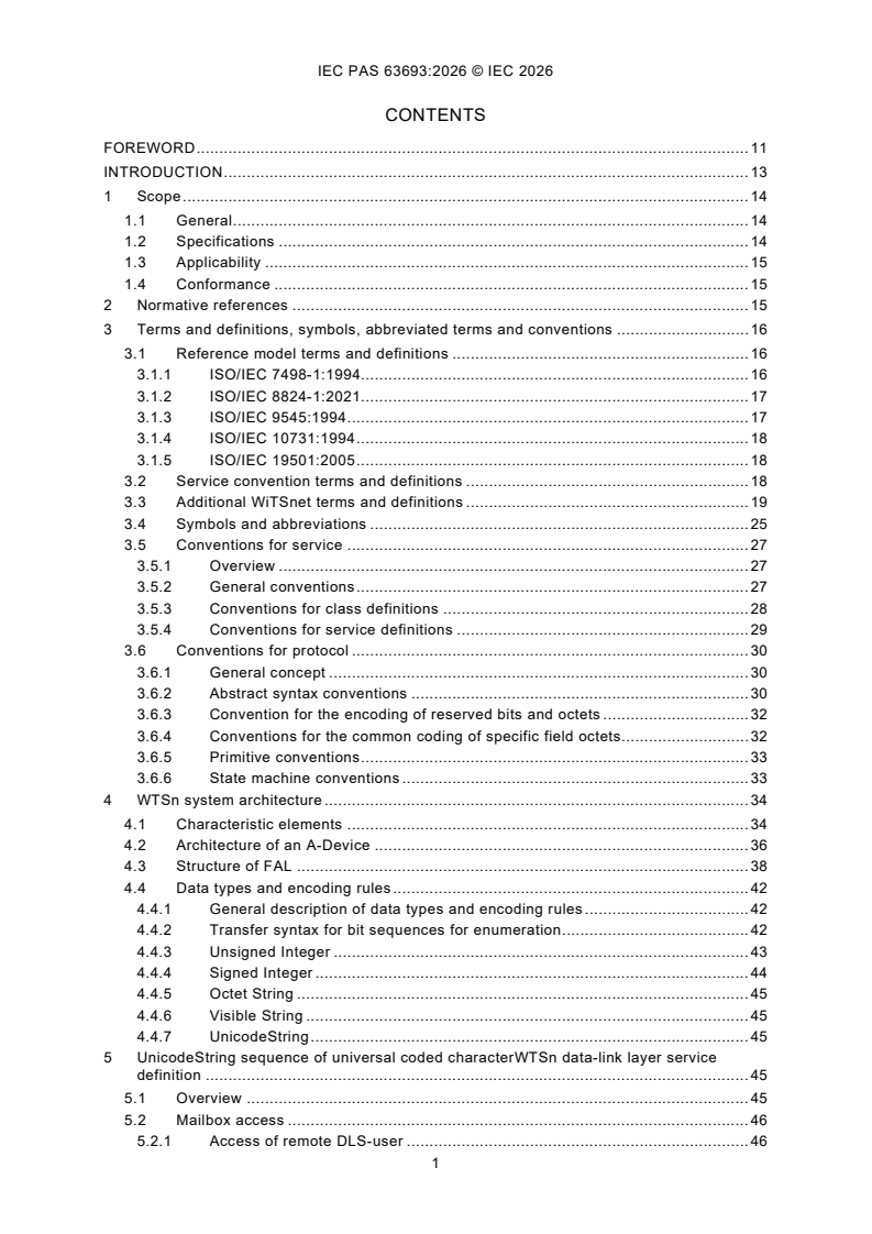
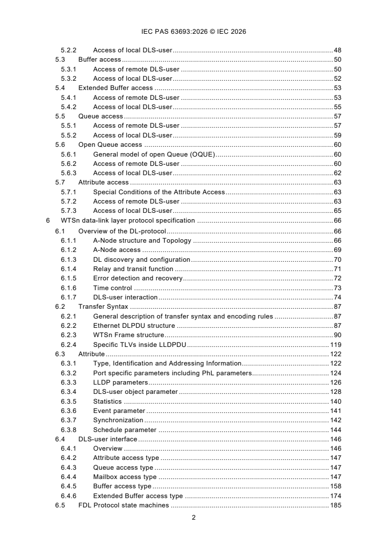
CONTENTS
FOREWORD . 11
INTRODUCTION . 13
1 Scope . 14
1.1 General . 14
1.2 Specifications . 14
1.3 Applicability . 15
1.4 Conformance . 15
2 Normative references . 15
3 Terms and definitions, symbols, abbreviated terms and conventions . 16
3.1 Reference model terms and definitions . 16
3.1.1 ISO/IEC 7498-1:1994. 16
3.1.2 ISO/IEC 8824-1:2021. 17
3.1.3 ISO/IEC 9545:1994 . 17
3.1.4 ISO/IEC 10731:1994 . 18
3.1.5 ISO/IEC 19501:2005 . 18
3.2 Service convention terms and definitions . 18
3.3 Additional WiTSnet terms and definitions . 19
3.4 Symbols and abbreviations . 25
3.5 Conventions for service . 27
3.5.1 Overview . 27
3.5.2 General conventions . 27
3.5.3 Conventions for class definitions . 28
3.5.4 Conventions for service definitions . 29
3.6 Conventions for protocol . 30
3.6.1 General concept . 30
3.6.2 Abstract syntax conventions . 30
3.6.3 Convention for the encoding of reserved bits and octets . 32
3.6.4 Conventions for the common coding of specific field octets. 32
3.6.5 Primitive conventions . 33
3.6.6 State machine conventions . 33
4 WTSn system architecture . 34
4.1 Characteristic elements . 34
4.2 Architecture of an A-Device . 36
4.3 Structure of FAL . 38
4.4 Data types and encoding rules . 42
4.4.1 General description of data types and encoding rules . 42
4.4.2 Transfer syntax for bit sequences for enumeration . 42
4.4.3 Unsigned Integer . 43
4.4.4 Signed Integer . 44
4.4.5 Octet String . 45
4.4.6 Visible String . 45
4.4.7 UnicodeString . 45
5 UnicodeString sequence of universal coded characterWTSn data-link layer service
definition . 45
5.1 Overview . 45
5.2 Mailbox access . 46
5.2.1 Access of remote DLS-user . 46
5.2.2 Access of local DLS-user . 48
5.3 Buffer access . 50
5.3.1 Access of remote DLS-user . 50
5.3.2 Access of local DLS-user . 52
5.4 Extended Buffer access . 53
5.4.1 Access of remote DLS-user . 53
5.4.2 Access of local DLS-user . 55
5.5 Queue access . 57
5.5.1 Access of remote DLS-user . 57
5.5.2 Access of local DLS-user . 59
5.6 Open Queue access . 60
5.6.1 General model of open Queue (OQUE) . 60
5.6.2 Access of remote DLS-user . 60
5.6.3 Access of local DLS-user . 62
5.7 Attribute access . 63
5.7.1 Special Conditions of the Attribute Access . 63
5.7.2 Access of remote DLS-user . 63
5.7.3 Access of local DLS-user . 65
6 WTSn data-link layer protocol specification . 66
6.1 Overview of the DL-protocol . 66
6.1.1 A-Node structure and Topology . 66
6.1.2 A-Node access . 69
6.1.3 DL discovery and configuration . 70
6.1.4 Relay and transit function . 71
6.1.5 Error detection and recovery . 72
6.1.6 Time control . 73
6.1.7 DLS-user interaction . 74
6.2 Transfer Syntax . 87
6.2.1 General description of transfer syntax and encoding rules . 87
6.2.2 Ethernet DLPDU structure . 87
6.2.3 WTSn Frame structure . 90
6.2.4 Specific TLVs inside LLDPDU . 119
6.3 Attribute . 122
6.3.1 Type, Identification and Addressing Information . 122
6.3.2 Port specific parameters including PhL parameters. 124
6.3.3 LLDP parameters . 126
6.3.4 DLS-user object parameter . 128
6.3.5 Statistics . 140
6.3.6 Event parameter . 141
6.3.7 Synchronization . 142
6.3.8 Schedule parameter . 144
6.4 DLS-user interface . 146
6.4.1 Overview . 146
6.4.2 Attribute access type . 147
6.4.3 Queue access type . 147
6.4.4 Mailbox access type . 147
6.4.5 Buffer access type . 158
6.4.6 Extended Buffer access type . 174
6.5 FDL Protocol state machines . 185
6.5.1 Overview of A-Node DL state machines . 185
6.5.2 General definitions for an Ethernet link segment operation . 185
6.5.3 Implementation option with a single Port . 186
6.5.4 Port Receive state machines (PRM) . 186
6.5.5 Relay, transit and scheduling state machines (RTSM) . 186
6.5.6 Port Transmit state machines (PTM) . 207
6.5.7 Subframe processing state machine (SFPM) . 209
6.5.8 Discovery state machines . 212
6.5.9 Synchronization . 222
7 WTSn application layer service definition. 229
7.1 Overview . 229
7.2 Data type ASE . 230
7.2.1 General . 230
7.2.2 Formal definition of data type objects . 230
7.2.3 FAL defined data types . 230
7.2.4 Data type ASE service specification. 236
7.3 Communication model specification . 236
7.3.1 Concepts . 236
7.3.2 Modular device ASE . 237
7.3.3 AR ASE . 252
7.3.4 Discovery ASE . 258
8 WTSn application layer protocol specification . 267
8.1 Coding of PDU elements . 267
8.1.1 APDU structure. 267
8.1.2 Common APDU elements . 267
8.1.3 Transfer Data . 271
8.1.4 Variable Attributes and Definition . 273
8.1.5 Discovery . 276
8.1.6 Exchange of Process Elements . 277
8.1.7 AR Control APDU . 278
8.1.8 IPv4Encapsulation . 281
8.2 AR handling . 282
8.2.1 General . 282
8.2.2 Primitive definitions . 284
8.2.3 AR State Machine . 286
8.3 Special elements in the data transmission . 293
8.3.1 General Rules for data allocation in packets . 293
8.3.2 Fragmentation . 294
8.3.3 Isochronous Interaction . 303
8.4 Modelling of management functions . 306
8.4.1 Overview . 306
8.4.2 Synchronization management . 306
8.4.3 Identification . 307
8.4.4 Topology Management . 308
8.4.5 Scheduling . 310
8.4.6 Event Monitoring . 313
8.5 Open protocol transmission. 314
8.5.1 Principles of Operation . 314
8.5.2 Using MAC Address Transfer . 314
8.5.3 Identification and assignment of TNA . 315
8.5.4 Actions on the edge of WTSn networks . 317
8.5.5 Relationship to management . 317
8.5.6 Access to object model . 318
8.6 SHIM . 318
8.6.1 General . 318
8.6.2 Handling . 318
8.7 Multiple A-Controller or A-Device instances in an A-Node . 319
8.7.1 General . 319
8.7.2 Multiple A-Controllers . 319
8.7.3 Multiple A-Devices with separate Ports . 319
8.7.4 Multiple A-Devices without separate Ports . 319
Bibliography . 320
Figure 1 – Common structure of specific fields . 32
Figure 2 – Structure of an A-Device/A-Node . 37
Figure 3 – AL structure of an A-Device . 42
Figure 4 – Set of 2 port A-Devices connected to an A-Controller . 67
Figure 5 – Structure of A-Nodes with transit ports within a network . 67
Figure 6 – Structure with subsection ring and loops . 68
Figure 7 – Structure with redundant A-Controller connection . 69
Figure 8 – Loopback and One-way method . 70
Figure 9 – Mailbox interactions . 78
Figure 10 – Mailbox unidirectional interactions . 79
Figure 11 – Buffer interaction from A-Controller to A-Device . 80
Figure 12 – Buffer interaction from A-Device to A-Controller . 81
Figure 13 – Input XBUF with successful previous transaction . 82
Figure 14 – Input XBUF with previous transaction failed . 83
Figure 15 – Output XBUF with successful previous transaction . 84
Figure 16 – Output XBUF with previous transaction failed . 85
Figure 17 – Aggregation of DL objects into a single Command Execution List . 86
Figure 18 – WTSn elements in an Ethernet packet . 87
Figure 19 – RTM components . 187
Figure 20 – Structure of an interval . 204
Figure 21 – PTM components . 208
Figure 22 – Structure of a single transmit queue . 208
Figure 23 – TNA incremental assignment . 213
Figure 24 – Model of clock synchronization . 224
Figure 25 – Measurement of the link delay . 225
Figure 26 – Determination of the Neighbor Frequency Difference . 226
Figure 27 – Distribution of startup parameters . 228
Figure 28 – Sequence of AR state interaction . 283
Figure 29 – AR state diagram . 286
Figure 30 – Example mapping steps of process elements . 293
Figure 31 – APDU types . 294
Figure 32 – Sequence of MBX interaction with request fragmentation . 295
Figure 33 – Sequence of MBX interaction with response fragmentation . 296
Figure 34 – Sequence of XBUF interaction with fragmentation . 297
Figure 35 – FRSM States . 297
Figure 36 – Isochronous Interactions . 304
Figure 37 – Interaction structure . 305
Figure 38 – Identification of a WTSn network . 308
Figure 39 – SHIM example . 318
Table 1 – PDU element description example . 31
Table 2 – Example attribute description . 32
Table 3 – State machine layout . 34
Table 4 – Description of state machine elements . 34
Table 5 – Characteristic features of WTSn DL protocol . 35
Table 6 – Transfer syntax for bit sequences . 43
Table 7 – Transfer syntax for Unsigned data types . 44
Table 8 – Transfer syntax for Integer data types . 45
Table 9 – DL-MBXwrite . 46
Table 10 – DL-MBXread. 47
Table 11 – DL-MBXset . 48
Table 12 – DL-MBXget . 49
Table 13 – DL-BUFwrite . 50
Table 14 – DL-BUFread . 51
Table 15 – DL-BUFset . 52
Table 16 – DL-BUFget . 52
Table 17 – DL-XBUFwrite . 53
Table 18 – DL-XBUFread . 54
Table 19 – DL-XBUFset . 55
Table 20 – DL-XBUFget . 56
Table 21 – DL-QUEwrite . 57
Table 22 – DL-QUEread. 58
Table 23 – DL-QUEset . 59
Table 24 – DL-QUEget . 59
Table 25 – DL-OQUEtransfer . 61
Table 26 – DL-OQUEset . 62
Table 27 – DL-OQUEget . 62
Table 28 – DL-REGwrite . 63
Table 29 – DL-REGread. 64
Table 30 – DL-ATTset . 65
Table 31 – DL-ATTget. 66
Table 32 – Types of Communication Relationship (CR) . 75
Table 33 – Command Execution List (CEL) description . 86
Table 34 – Command Execution List in an A-Node . 86
Table 35 – WTSn frame inside an Ethernet packet . 87
Table 36 – WTSn frame inside a UDP PDU . 88
Table 37 – LLDP frame inside an Ethernet frame . 89
Table 38 – FCS octets of an erroneous Packet . 90
Table 39 – WTSn Frame common header structure . 91
Table 40 – TNA Definition . 92
Table 41 – WTSn FrameA structure containing WTSn PDU . 93
Table 42 – Buffer Read (BFRD) . 94
Table 43 – Buffer Write (BFWT) . 95
Table 44 – Buffer multiple Write (BFmW) . 97
Table 45 – Buffer Read and multiple Write (BFRmW) . 98
Table 46 – Buffer Read Write (BFRW) . 100
Table 47 – Extended Buffer Read (XBRD) . 101
Table 48 – Extended Buffer Write (XBWT) . 103
Table 49 – Mailbox Read (MBRD) . 105
Table 50 – Mailbox Write (MBWT). 106
Table 51 – Queue Read (QURD). 108
Table 52 – Queue Write (QUWT) . 109
Table 53 – Command Execution List (CEL) . 111
Table 54 – Register Read (RGRD) . 112
Table 55 – Register Write (RGWT). 114
Table 56 – Register multiple Write (RGmW) . 115
Table 57 – Register Read and multiple Write (RGRmW) . 116
Table 58 – Register Mask Write (RGmsWT) . 118
Table 59 – TLV elements . 119
Table 60 – WTSn identification and TNA setup . 120
Table 61 – WTSn topology subtree . 121
Table 62 – Node information . 123
Table 63 – Link control/status . 125
Table 64 – LLDP attributes . 126
Table 65 – CR-bundle attributes . 129
Table 66 – Mailbox attributes . 131
Table 67 – Buffer attributes. 132
Table 68 – XBuffer attributes . 135
Table 69 – Queue attributes . 137
Table 70 – CEL attributes . 139
Table 71 – Multicast attributes . 140
Table 72 – TX/RX counters . 140
Table 73 – Additional counters . 141
Table 74 – Event structure . 141
Table 75 – Link local measurement . 143
Table 76 – Clock parameter . 144
Table 77 – Interval layout . 145
Table 78 – Interval specification . 145
Table 79 – Scheduler packet list attributes . 146
Table 80 – Primitives issued by SFPM to MBX . 148
Table 81 – Primitives issued by MBX to SFPM . 148
Table 82 – Primitives issued by DLS-user to MBX . 149
Table 83 – Primitives issued by MBX to DLS-user . 149
Table 84 – Parameters of the primitives . 149
Table 85 – MBX Variables . 150
Table 86 – MBX state table . 150
Table 87 – MBXr Variables . 154
Table 88 – MBXr state table . 155
Table 89 – Primitives issued by SFPM to OBUF . 159
Table 90 – Primitive issued by OBUF to SFPM . 159
Table 91 – Primitive issued by DLS-user to OBUF . 159
Table 92 – Primitive issued by OBUF to DLS-user . 159
Table 93 – Parameters of the primitives . 160
Table 94 – OBUF Variables . 160
Table 95 – Transfer of Output Buffers overview . 160
Table 96 – OBUF state table . 161
Table 97 – Primitives issued by SFPM to OBUFr . 163
Table 98 – Primitives issued by OBUFr to SFPM . 163
Table 99 – Primitives issued by DLS-user to OBUFr . 163
Table 100 – Primitives issued by OBUFr to DLS-user . 163
Table 101 – OBUFr Variables and Functions . 164
Table 102 – Transfer of redundant Output Buffers overview . 164
Table 103 – OBUFr state table . 165
Table 104 – Primitives issued by SFPM to IBUF . 167
Table 105 – Primitive issued by IBUF to SFPM . 167
Table 106 – Primitive issued by DLS-user to IBUF . 168
Table 107 – Primitive issued by IBUF to DLS-user . 168
Table 108 – Parameters of the primitives . 168
Table 109 – IBUF Variables . 169
Table 110 – Transfer of Input Buffers overview . 169
Table 111 – IBUF state table . 170
Table 112 – Primitives issued by SFPM to IBUFr . 171
Table 113 – Primitives issued by IBUFr to SFPM . 172
Table 114 – IBUFr Variables and Functions . 172
Table 115 – Transfer of redundant Input Buffers overview . 173
Table 116 – IBUFr state table . 173
Table 117 – Primitives issued by SFPM to OXBUF . 175
Table 118 – Primitive issued by OXBUF to SFPM . 175
Table 119 – Primitive issued by DLS-user to OXBUF . 176
Table 120 – Primitive issued by OXBUF to DLS-user . 176
Table 121 – Parameters of the primitives . 176
Table 122 – OXBUF Variables . 177
Table 123 – OXBUF state table. 177
Table 124 – Primitives issued by SFPM to IXBUF . 180
Table 125 – Primitive issued by IXBUF to SFPM . 180
Table 126 – Primitive issued by DLS-user to IXBUF . 180
Table 127 – Primitive issued by IXBUF to DLS-user . 181
Table 128 – Parameters of the primitives . 181
Table 129 – IXBUF Variables . 181
Table 130 – IXBUF state table . 182
Table 131 – Primitives issued by PRM to Parser . 188
Table 132 – Primitives between Parser and DelayFifo . 188
Table 133 – Primitives between Parser and TNA Handler . 188
Table 134 – Primitive between Parser and SFPM . 188
Table 135 – Primitive between Parser and Frame Conversion . 189
Table 136 – Primitive between SFPM and OutboundFifo . 189
Table 137 – Primitive between Frame Conversion and OutboundFifo . 189
Table 138 – Parameters of the primitives . 189
Table 139 – Parser Variables . 190
Table 140 – Parser decision list of Ethernet Packet structure . 191
Table 141 – WTSn Frame common elements decision list . 193
Table 142 – Parameter and Functions . 196
Table 143 – WTSn SubFrame decision list . 196
Table 144 – Determination of the target port . 198
Table 145 – Redundant Transmission Variables and Functions . 199
Table 146 – Determination of the target port with redundancy . 200
Table 147 – Parameter of an interval specification . 204
Table 148 – Example Interval layout . 206
Table 149 – Example parameter set of an interval specification . 207
Table 150 – Default multicast setting . 209
Table 151 – Functions for checking subframe information . 209
Table 152 – Checking Subfram
...