

IEC TR 60664-2-1:2026
(Main)Insulation coordination for equipment within low-voltage systems - Part 2-1: Application guide - Explanation of the application of the IEC 60664 series, dimensioning examples and dielectric testing
- Abstract
IEC TR 60664-2-1:2026 serves as an application guide, when using the IEC 60664 series for the design and verification of an insulation system of electrical equipment within low-voltage systems, in order to provide better understanding related to the:
- basic technical characteristics relevant for the design of clearances, creepage distances, and solid insulation,
- design for insulation coordination to clearances, creepage distances, and solid insulation and combinations of such,
- test and measurement of clearances, creepage distances, and solid insulation for electrical equipment and their components,
- practical examples for dimensioning of clearances, creepage distances and solid insulation.
This document is informative only and does not provide any additional requirements beyond the IEC 60664 series. It provides guidance to assist better understanding of the insulation coordination requirements and avoids repeating the content of the individual parts of IEC 60664 documents. In case of conflict between this document and documents mentioned above, requirements in these documents prevail over this technical report.
This document provides a summary for technical committees in the preparation of their standards, and for manufacturers of electrical equipment and components, on specific topics, activities and options which are considered when using the IEC 60664 series in their specific equipment or application. See Annex A.
This basic safety publication focusing on safety guidance related to IEC 60664 series is primarily intended for use by technical committees in the preparation of safety publications in accordance with the principles laid down in and.
One of the responsibilities of a technical committee is, wherever applicable, to make use of basic safety publications in the preparation of its publications.
This edition includes the following significant technical changes with respect to the previous edition:
- the third edition of this technical report is reconstructed to align with the structure of 60664-1:2020 and 60664-1:2020/AMD1:2025;
- reference numbers indicated in this technical report are updated in line with the changes to clause and table numbers in 60664-1:2020 and 60664-1:2020/AMD1:2025;
- references to 60664-5:2007, withdrawn in 2014, are deleted, and replaced, where applicable, to reference to TR 63040 ;
- explanations of the principles of IEC 60664 series and examples of practical application are improved;
- Table A.1, Table A.2, and Table A.3 are combined into one table;
- Annex B, Annex C, and Annex D are deleted.
- Status
- Published
- Publication Date
- 10-Nov-2026
- Technical Committee
- TC 109 - Insulation co-ordination for low-voltage equipment
- Drafting Committee
- MT 1 - TC 109/MT 1
- Current Stage
- PPUB - Publication issued
- Start Date
- 11-Nov-2026
- Completion Date
- 09-Oct-2026
Buy Documents
IEC TR 60664-2-1:2026 - Insulation coordination for equipment within low-voltage systems - Part 2-1: Application guide - Explanation of the application of the IEC 60664 series, dimensioning examples and dielectric testing
IEC TR 60664-2-1:2026 is an IEC technical report that acts as an application guide to the IEC 60664 series for insulation coordination in electrical equipment within low-voltage systems. It explains how to use the series for design, verification, testing and measurement of clearances, creepage distances and solid insulation, and it includes practical dimensioning examples. IEC TR 60664-2-1:2026 is informative only - it adds no requirements beyond the IEC 60664 series, and where there is a conflict, the IEC 60664 requirements prevail.
What does IEC TR 60664-2-1:2026 specify?
IEC TR 60664-2-1:2026 provides guidance for understanding and applying insulation coordination in low-voltage equipment. It is aimed at designers, manufacturers and technical committees that need to apply the IEC 60664 series to a specific product or application.
The document explains the main technical factors that influence insulation design, how to dimension clearances, creepage distances and solid insulation, how to check them, and how to use practical examples and worksheets. It is organized into clauses on scope, normative references, terms, basic technical characteristics, design, tests and measurements, practical examples, and worksheet examples, plus Annex A.
The structure is:
- Clause 1 - Scope
- Clause 2 - Normative references
- Clause 3 - Terms, definitions and abbreviated terms
- Clause 4 - Basic technical characteristics for insulation coordination
- Clause 5 - Design for insulation coordination
- Clause 6 - Tests and measurements
- Clause 7 - Practical examples for dimensioning of insulation
- Clause 8 - Examples of a dimensioning worksheet
- Annex A - Overview of clauses of IEC 60664-1 for considerations and decisions by technical committee or the manufacturer
What are the key requirements of IEC TR 60664-2-1:2026?
IEC TR 60664-2-1:2026 is a guidance document, so its practical value is in showing how to apply the IEC 60664 series in design and verification. The most important points are the factors to consider, the way the insulation types are dimensioned, and the test and measurement logic that supports the design.
How the document frames insulation coordination
Clause 4.1 says insulation coordination must be read in context. IEC TR 60664-2-1:2026 distinguishes between the electrical stresses present in the installation, the stresses generated by the equipment itself, and the purpose of the insulation, such as basic function, safety, reliability or a safe internal function.
That matters because the document is not only about protection against electric shock. It also points technical committees toward other hazards and design goals, including fire, explosive atmosphere and functional safety, so the chosen insulation type and verification method fit the actual risk.
How clearances are chosen
Clause 4 and Clause 5 show that clearance design depends on the voltage conditions, overvoltage category, pollution degree, altitude and field distribution. IEC TR 60664-2-1:2026 explains that the default case is inhomogeneous field conditions, while approximate homogeneous field conditions can justify optimized, smaller clearances if verification is carried out.
This matters in practice because clearance is not a single fixed number. The reader has to identify the stress case, decide whether the design is based on transient overvoltage or steady-state voltage, and then check whether altitude or field shape changes the distance needed.
How creepage distances are chosen
Clause 5.3 explains that creepage distance depends on voltage, pollution degree and material group, with further influence from surface shape, orientation, voltage duration, ribs, floating conductive parts and mixed materials. It also explains the relationship between creepage distance and clearance, including cases where one can govern the other.
The practical effect is that a surface path cannot be treated like an air gap. The designer has to look at contamination, humidity, the insulation surface and the material characteristics, not just the spacing between conductors.
How solid insulation is treated
Clause 5.4 covers design of solid insulation, including coordination with clearances, dimensioning by breakdown field strength and dimensioning by testing. Clause 5.5 then explains combination designs where clearance and solid insulation act in series, including cases where air gaps or air bubbles create a combined stress path.
This matters because a piece of solid insulation can still fail if internal voids or manufacturing imperfections create local stress. The document therefore pushes the reader to think about both material strength and the electrical path through the insulation system.
How parallel insulation paths are handled
Clause 5.6 addresses clearances and solid insulation in parallel for reinforced insulation. IEC TR 60664-2-1:2026 explains that the parallel path changes how the test voltage and the design distance are considered for the combined insulation system.
In practice, this prevents the designer from checking only one part of the insulation path. Both the air path and the solid path have to be accounted for as part of the same safety concept.
How verification is done
Clause 6 separates verification of clearances, creepage distances and solid insulation. Creepage distances are verified by measurement and inspection, not by voltage test alone, while solid insulation may require dielectric and partial discharge-related checks depending on the stress case.
This is important for quality control and certification work. It tells the reader which proof method fits which insulation feature, and where a measurement, a test or both are needed.
How the examples should be used
Clause 7 and Clause 8 show worked application examples and worksheet logic. They use case-based examples for Class I and Class II equipment, and they compare clearances and creepage distances under different assumptions, including overvoltage category, pollution degree and the location of the circuit.
That helps engineers translate the abstract rules into a calculation or review process. It is especially useful when preparing a product standard, a design file or a verification worksheet.
What terms does IEC TR 60664-2-1:2026 define?
IEC TR 60664-2-1:2026 uses terms and definitions from IEC 60664-1:2020, IEC 60664-1:2020/AMD1:2025, IEC 60664-3:2016 and IEC 60664-4:2005, and it adds these abbreviations in Clause 3.2.
- Surge protective device (SPD) - A device connected to low-voltage power systems for surge protection, used when the installation includes surge suppression.
- Surge protective component (SPC) - A component used in low-voltage surge protective devices, relevant when the insulation design depends on surge protection inside the equipment.
- Overvoltage category (OVC) - The category used to describe transient overvoltage conditions at the installation point, and a key input to clearance design.
- Temporary overvoltage (TOV) - A temporary voltage stress condition that affects the selection of clearance and insulation verification.
- Comparative tracking index (CTI) - An indicator used when selecting creepage distance, because it relates to how the insulating material behaves on its surface under pollution.
- Clearance - The air distance between conductive parts that the document sizes and verifies for dielectric withstand.
- Creepage distance - The surface distance along insulating material between conductive parts, used to address pollution and tracking.
- Solid insulation - Insulation provided by a solid material, which the document treats separately from air spacing because its failure modes are different.
Who uses IEC TR 60664-2-1:2026?
IEC TR 60664-2-1:2026 is primarily intended for technical committees preparing safety publications and product standards. It is also written for manufacturers of electrical equipment and components that need to apply the IEC 60664 series to a specific design.
In practice, it is used by people who have to decide:
- which insulation type applies in a product or subsystem
- how to size clearances and creepage distances
- how to verify solid insulation
- how to interpret dielectric test and measurement methods
- how to document a worksheet or design rationale for a standard, product file or verification package
What changed in IEC TR 60664-2-1:2026 from the previous edition?
IEC TR 60664-2-1:2026 is the third edition of the technical report. The edition notes state these changes from the previous edition:
- the report was reconstructed to align with the structure of IEC 60664-1:2020 and IEC 60664-1:2020/AMD1:2025
- reference numbers were updated to match the revised clause and table numbering in those documents
- references to IEC 60664-5:2007 were deleted and replaced, where applicable, by references to TR 63040
- the explanations of the IEC 60664 principles and practical application examples were improved
- Table A.1, Table A.2 and Table A.3 were combined into one table
- Annex B, Annex C and Annex D were deleted
Which standards are used with IEC TR 60664-2-1:2026?
IEC TR 60664-2-1:2026 uses the following normative references:
- IEC 60664-1:2020 - supplies the core principles, requirements and tests for insulation coordination, and provides the main rules that this technical report explains and illustrates.
- IEC 60664-1:2020/AMD1:2025 - updates the base document that this technical report follows, including the changed clause and table references used throughout the examples.
- IEC 60664-3:2016 - provides the guidance for coating, potting or moulding used for protection against pollution, which is referenced where reduced distances are discussed.
- IEC 60664-4:2005 - provides the method for considering high-frequency voltage stress, which is used in the frequency-related parts of the guide.
What does the IEC TR 60664-2-1:2026 document contain?
IEC TR 60664-2-1:2026 contains explanatory text, clause-by-clause guidance, practical examples and a worksheet-oriented approach. Clause 4 explains the technical factors that shape insulation coordination, while Clause 5 develops the design logic for clearances, creepage distances, solid insulation and combined insulation paths.
The document also contains figures that illustrate field distribution, grooves, floating conductive parts and equipment examples, plus tables and examples that compare insulation choices for different equipment classes and operating conditions. Clause 6 describes verification methods, including dielectric tests and measurement practice, and Clause 8 gives worksheet examples for applying the IEC 60664-1 and IEC 60664-4 logic to specific circuits.
Annex A gives an overview of the clauses of IEC 60664-1 that require consideration or decisions by technical committees or manufacturers. In practice, that annex works as a checklist for standard writers and product developers who need to decide which parts of the insulation coordination model apply to their equipment.
Relations
- Effective Date
- 07-Mar-2025
- Effective Date
- 12-Apr-2024
Buy Documents
IEC TR 60664-2-1:2026 - Insulation coordination for equipment within low-voltage systems - Part 2-1: Application guide - Explanation of the application of the IEC 60664 series, dimensioning examples and dielectric testing
Get Certified
Connect with accredited certification bodies for this standard

IMQ S.p.A. (Certification)
Italian electrical product certification.

SLG Prüf- und Zertifizierungs GmbH
German testing and certification body.

UL Solutions
Global safety science company with testing, inspection and certification.
Sponsored listings
Frequently Asked Questions
IEC TR 60664-2-1:2026 is a technical report published by the International Electrotechnical Commission (IEC). Its full title is "Insulation coordination for equipment within low-voltage systems - Part 2-1: Application guide - Explanation of the application of the IEC 60664 series, dimensioning examples and dielectric testing". This standard covers: IEC TR 60664-2-1:2026 serves as an application guide, when using the IEC 60664 series for the design and verification of an insulation system of electrical equipment within low-voltage systems, in order to provide better understanding related to the: - basic technical characteristics relevant for the design of clearances, creepage distances, and solid insulation, - design for insulation coordination to clearances, creepage distances, and solid insulation and combinations of such, - test and measurement of clearances, creepage distances, and solid insulation for electrical equipment and their components, - practical examples for dimensioning of clearances, creepage distances and solid insulation. This document is informative only and does not provide any additional requirements beyond the IEC 60664 series. It provides guidance to assist better understanding of the insulation coordination requirements and avoids repeating the content of the individual parts of IEC 60664 documents. In case of conflict between this document and documents mentioned above, requirements in these documents prevail over this technical report. This document provides a summary for technical committees in the preparation of their standards, and for manufacturers of electrical equipment and components, on specific topics, activities and options which are considered when using the IEC 60664 series in their specific equipment or application. See Annex A. This basic safety publication focusing on safety guidance related to IEC 60664 series is primarily intended for use by technical committees in the preparation of safety publications in accordance with the principles laid down in and. One of the responsibilities of a technical committee is, wherever applicable, to make use of basic safety publications in the preparation of its publications. This edition includes the following significant technical changes with respect to the previous edition: - the third edition of this technical report is reconstructed to align with the structure of 60664-1:2020 and 60664-1:2020/AMD1:2025; - reference numbers indicated in this technical report are updated in line with the changes to clause and table numbers in 60664-1:2020 and 60664-1:2020/AMD1:2025; - references to 60664-5:2007, withdrawn in 2014, are deleted, and replaced, where applicable, to reference to TR 63040 ; - explanations of the principles of IEC 60664 series and examples of practical application are improved; - Table A.1, Table A.2, and Table A.3 are combined into one table; - Annex B, Annex C, and Annex D are deleted.
IEC TR 60664-2-1:2026 serves as an application guide, when using the IEC 60664 series for the design and verification of an insulation system of electrical equipment within low-voltage systems, in order to provide better understanding related to the: - basic technical characteristics relevant for the design of clearances, creepage distances, and solid insulation, - design for insulation coordination to clearances, creepage distances, and solid insulation and combinations of such, - test and measurement of clearances, creepage distances, and solid insulation for electrical equipment and their components, - practical examples for dimensioning of clearances, creepage distances and solid insulation. This document is informative only and does not provide any additional requirements beyond the IEC 60664 series. It provides guidance to assist better understanding of the insulation coordination requirements and avoids repeating the content of the individual parts of IEC 60664 documents. In case of conflict between this document and documents mentioned above, requirements in these documents prevail over this technical report. This document provides a summary for technical committees in the preparation of their standards, and for manufacturers of electrical equipment and components, on specific topics, activities and options which are considered when using the IEC 60664 series in their specific equipment or application. See Annex A. This basic safety publication focusing on safety guidance related to IEC 60664 series is primarily intended for use by technical committees in the preparation of safety publications in accordance with the principles laid down in and. One of the responsibilities of a technical committee is, wherever applicable, to make use of basic safety publications in the preparation of its publications. This edition includes the following significant technical changes with respect to the previous edition: - the third edition of this technical report is reconstructed to align with the structure of 60664-1:2020 and 60664-1:2020/AMD1:2025; - reference numbers indicated in this technical report are updated in line with the changes to clause and table numbers in 60664-1:2020 and 60664-1:2020/AMD1:2025; - references to 60664-5:2007, withdrawn in 2014, are deleted, and replaced, where applicable, to reference to TR 63040 ; - explanations of the principles of IEC 60664 series and examples of practical application are improved; - Table A.1, Table A.2, and Table A.3 are combined into one table; - Annex B, Annex C, and Annex D are deleted.
IEC TR 60664-2-1:2026 is classified under the following ICS (International Classification for Standards) categories: 29.080.30 - Insulation systems. The ICS classification helps identify the subject area and facilitates finding related standards.
IEC TR 60664-2-1:2026 has the following relationships with other standards: It is inter standard links to IEC 60664-2-1:2011/COR1:2011, IEC TR 60664-2-1:2011. Understanding these relationships helps ensure you are using the most current and applicable version of the standard.
IEC TR 60664-2-1:2026 is available in PDF format for immediate download after purchase. The document can be added to your cart and obtained through the secure checkout process. Digital delivery ensures instant access to the complete standard document.
Standards Content (Sample)
IEC TR 60664-2-1 ®
Edition 3.0 2026-11
TECHNICAL
REPORT
BASIC SAFETY PUBLICATION
HORIZONTAL PUBLICATION
Insulation coordination for equipment within low-voltage systems
Part 2-1: Application guide - Explanation of the application of the IEC 60664
series, dimensioning examples and dielectric testing
ICS 29.080.30 ISBN 978-2-8327-1482-9
All rights reserved. Unless otherwise specified, no part of this publication may be reproduced or utilized in any form or
by any means, electronic or mechanical, including photocopying and microfilm, without permission in writing from either
IEC or IEC's member National Committee in the country of the requester. If you have any questions about IEC copyright
or have an enquiry about obtaining additional rights to this publication, please contact the address below or your local
IEC member National Committee for further information.
IEC Secretariat Tel.: +41 22 919 02 11
3, rue de Varembé info@iec.ch
CH-1211 Geneva 20 www.iec.ch
Switzerland
About the IEC
The International Electrotechnical Commission (IEC) is the leading global organization that prepares and publishes
International Standards for all electrical, electronic and related technologies.
About IEC publications
The technical content of IEC publications is kept under constant review by the IEC. Please make sure that you have the
latest edition, a corrigendum or an amendment might have been published.
IEC publications search - IEC Products & Services Portal - products.iec.ch
webstore.iec.ch/advsearchform Discover our powerful search engine and read freely all the
The advanced search enables to find IEC publications by a publications previews, graphical symbols and the glossary.
variety of criteria (reference number, text, technical With a subscription you will always have access to up to date
committee, …). It also gives information on projects, content tailored to your needs.
replaced and withdrawn publications.
Electropedia - www.electropedia.org
The world's leading online dictionary on electrotechnology,
IEC Just Published - webstore.iec.ch/justpublished
Stay up to date on all new IEC publications. Just Published containing more than 22 500 terminological entries in English
details all new publications released. Available online and and French, with equivalent terms in 25 additional languages.
once a month by email. Also known as the International Electrotechnical Vocabulary
(IEV) online.
IEC Customer Service Centre - webstore.iec.ch/csc
If you wish to give us your feedback on this publication or
need further assistance, please contact the Customer
Service Centre: sales@iec.ch.
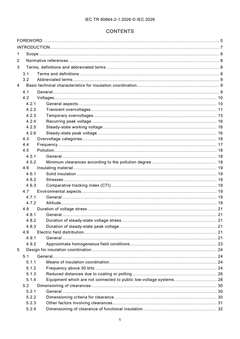
CONTENTS
FOREWORD . 5
INTRODUCTION . 7
1 Scope . 8
2 Normative references . 8
3 Terms, definitions and abbreviated terms . 8
3.1 Terms and definitions . 8
3.2 Abbreviated terms . 9
4 Basic technical characteristics for insulation coordination . 9
4.1 General . 9
4.2 Voltages . 10
4.2.1 General aspects . 10
4.2.2 Transient overvoltages . 11
4.2.3 Temporary overvoltages . 15
4.2.4 Recurring peak voltage . 16
4.2.5 Steady-state working voltage . 16
4.2.6 Steady-state peak voltage . 16
4.3 Overvoltage categories . 16
4.4 Frequency . 17
4.5 Pollution . 18
4.5.1 General . 18
4.5.2 Minimum clearances according to the pollution degree . 18
4.6 Insulating material . 19
4.6.1 Solid insulation . 19
4.6.2 Stresses . 19
4.6.3 Comparative tracking index (CTI) . 19
4.7 Environmental aspects. 19
4.7.1 General . 19
4.7.2 Altitude. 19
4.8 Duration of voltage stress . 21
4.8.1 General . 21
4.8.2 Duration of steady-state voltage stress . 21
4.8.3 Duration of steady-state peak voltage . 21
4.9 Electric field distribution . 21
4.9.1 General . 21
4.9.2 Approximate homogeneous field conditions . 23
5 Design for insulation coordination . 24
5.1 General . 24
5.1.1 Means of insulation coordination . 24
5.1.2 Frequency above 30 kHz . 24
5.1.3 Reduced distances due to coating or potting . 26
5.1.4 Equipment which are not connected to public low-voltage systems . 28
5.2 Dimensioning of clearances . 30
5.2.1 General . 30
5.2.2 Dimensioning criteria for clearance . 30
5.2.3 Other factors involving clearances. 31
5.2.4 Dimensioning of clearance of functional insulation . 32
5.2.5 Dimensioning of clearances of basic insulation, supplementary insulation and reinforced
insulation . 32
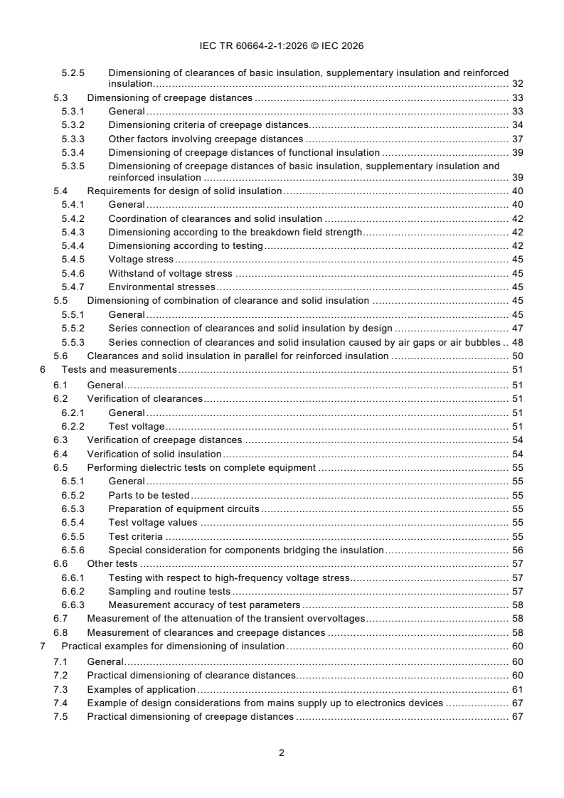
5.3 Dimensioning of creepage distances . 33
5.3.1 General . 33
5.3.2 Dimensioning criteria of creepage distances. 34
5.3.3 Other factors involving creepage distances . 37
5.3.4 Dimensioning of creepage distances of functional insulation . 39
5.3.5 Dimensioning of creepage distances of basic insulation, supplementary insulation and
reinforced insulation . 39
5.4 Requirements for design of solid insulation . 40
5.4.1 General . 40
5.4.2 Coordination of clearances and solid insulation . 42
5.4.3 Dimensioning according to the breakdown field strength . 42
5.4.4 Dimensioning according to testing . 42
5.4.5 Voltage stress . 45
5.4.6 Withstand of voltage stress . 45
5.4.7 Environmental stresses . 45
5.5 Dimensioning of combination of clearance and solid insulation . 45
5.5.1 General . 45
5.5.2 Series connection of clearances and solid insulation by design . 47
5.5.3 Series connection of clearances and solid insulation caused by air gaps or air bubbles . 48
5.6 Clearances and solid insulation in parallel for reinforced insulation . 50
6 Tests and measurements . 51
6.1 General . 51
6.2 Verification of clearances . 51
6.2.1 General . 51
6.2.2 Test voltage . 51
6.3 Verification of creepage distances . 54
6.4 Verification of solid insulation . 54
6.5 Performing dielectric tests on complete equipment . 55
6.5.1 General . 55
6.5.2 Parts to be tested . 55
6.5.3 Preparation of equipment circuits . 55
6.5.4 Test voltage values . 55
6.5.5 Test criteria . 55
6.5.6 Special consideration for components bridging the insulation . 56
6.6 Other tests . 57
6.6.1 Testing with respect to high-frequency voltage stress . 57
6.6.2 Sampling and routine tests . 57
6.6.3 Measurement accuracy of test parameters . 58
6.7 Measurement of the attenuation of the transient overvoltages . 58
6.8 Measurement of clearances and creepage distances . 58
7 Practical examples for dimensioning of insulation . 60
7.1 General . 60
7.2 Practical dimensioning of clearance distances. 60
7.3 Examples of application . 61
7.4 Example of design considerations from mains supply up to electronics devices . 67
7.5 Practical dimensioning of creepage distances . 67
8 Examples of a dimensioning worksheet (based on case A as described in IEC 60664-1:2020 [2]
and IEC 60664-1:2020/AMD1:2025 [3]) . 67
8.1 Use of IEC 60664-1 [9], for circuits in equipment either directly or not directly connected to
the mains supply . 67
8.2 Use of IEC 60664-4 [12], for circuits in equipment either directly or not directly connected to
the mains supply . 68
8.3 Examples of dimension comparison for clearances and creepage distances according to
IEC 60664-1:2020 [2], IEC 60664-1:2020/AMD1:2025 [3] and IEC 60664-4:2005 [8] based
on case A condition (basic insulation, for equipment up to 2 000 m altitude) . 70
8.3.1 General . 70
8.3.2 Example of circuits not directly connected to mains supply . 70
Annex A (informative) Overview of clauses of IEC 60664-1 [9] for considerations and decisions by
technical committee or the manufacturer . 74
Bibliography . 79
Figure 1 – Typical example of the application of overvoltage categories (OVCs) . 17
Figure 2 – Principle of Paschen's law impacting the insulation behaviour of atmospheric air . 20
Figure 3 – Example of homogeneous field . 22
Figure 4 – Example of inhomogeneous field . 22
Figure 5 – Example of approximately homogenous field . 22
Figure 6 – Principle of electric breakdown due to avalanche of electrons . 23
Figure 7 – Spacings on multi-layer printed wiring material . 27
Figure 8 – Example of electrical distribution with renewable sources in a new building . 29
Figure 9 – Example of electrical distribution with renewable sources in an existing building . 30
Figure 10 – Example of creepage distances less than applicable clearances . 35
Figure 11 – Creepage distances increased to the applicable clearances . 36
Figure 12 – Creepage distances increased to the applicable clearances with different materials . 36
Figure 13 – Example of creepage distances split into two different materials in the same
pollution degree . 37
Figure 14 – Example of creepage distances split into two different pollution degrees on the same
insulating material . 38
Figure 15 – Creepage distances across the surface of printed wiring material and component . 39
Figure 16 – Breakdown voltage of solid insulation depending upon the time of voltage stress . 41
Figure 17 – Series connection of clearance and solid insulation . 45
Figure 18 – Capacitive voltage divider . 46
Figure 19 – Example: Clearances and solid insulation in parallel for reinforced insulation . 50
Figure 20 – Arrangement for AC (or DC) voltage test . 56
Figure 21 – Clearances and creepage distances across a groove in combination of IEC 60664-1:2020 [2]
and IEC 60664-1:2020/AMD1:2025 [3], Figure 5 and Figure 6 . 58
Figure 22 – Clearance and creepage distance with conductive floating part . 59
Figure 23 – Simple illustration of insulation system containing functional, basic and reinforced or double
insulation for class I equipment . 61
Figure 24 – Example 1 - Dimensioning of clearances for Class I equipment, based on overvoltage
category III . 61
Figure 25 – Example 2 - Dimensioning of clearances (Class I equipment) . 63
Figure 26 – Example 3 - Dimensioning of clearances (Class II equipment) . 65
Table 1 – Examples of test voltages for equipment rated voltage 100 V and 230 V in
overvoltage category II . 44
Table 2 – Example of test voltages to verify clearances at test site altitudes lower than 2 000 m . 52
Table 3 – Example of test voltages to verify clearances at test site altitudes higher than 2 000 m . 52
Table 4 – IEC 60664-1:2020 [2], Table F.2 with linear interpolation . 53
Table 5 – Test voltage multiplication factor K . 54
u
Table 6 – Example 1 - Dimensioning of clearances according to IEC 60664-1:2020 [2], Table F.2
(pollution degree 2) . 62
Table 7 – Example 1 - Dimensioning of clearances according to impulse withstand voltages
(IEC 60664-1:2020 [2], Table F.2) and steady-state peak voltage, temporary overvoltages and
recurring peak voltages (IEC 60664-1:2020 [2], Table F.8). . 62
Table 8 – Example 2 - Dimensioning of clearances according to IEC 60664-1:2020 [2], Table F.2
(pollution degree 2) . 64
Table 9 – Example 2 - Dimensioning of clearances according to IEC 60664-1:2020 [2], Table F.2
and Table F.8, temporary overvoltages according to IEC 60664-1:2020 [2]
and IEC 60664-1:2020/AMD1:2025 [3], 5.4.3.2 (U + 1 200 V) . 64
n
Table 10 – Example 3 - Dimensioning of clearances according to IEC 60664-1:2020 [2], Table F.2
(pollution degree 2) . 66
Table 11 – Example 3 - Dimensioning of clearances according to IEC 60664-1:2020 [2], Table F.2
and Table F.8, temporary overvoltages according to IEC 60664-1:2020 [2] and
IEC 60664-1:2020/AMD1:2025 [3], 5.4.3.2 (U + 1 200 V) . 66
n
Table 12 – Relationship between influencing parameters and normative references in
IEC 60664-1:2020 [2] and IEC 60664-1:2020/AMD1:2025 [3] . 67
Table 13 – Relationship between influencing parameters and normative references in
IEC 60664-1:2020 [2], IEC 60664-1:2020/AMD1:2025 [3] and IEC 60664-4:2005 [8] . 68
Table 14 – Example 1 for dimensioning a clearance and creepage distance following IEC 60664-1 [9]
in circuits not directly connected to mains supply . 71
Table 15 – Example 1 for dimensioning a clearance and creepage distance following
IEC 60664-4:2005 [8] (approximately homogeneous field) . 71
Table 16 – Example 2 for dimensioning a clearance and creepage distance following IEC 60664-1 [9]
in circuits not directly connected to mains supply . 72
Table 17 – Example 2 for dimensioning a clearance and creepage distance following
IEC 60664-4:2005 [8] (approximately homogeneous field) . 73
Table A.1 – Clauses and subclauses of IEC 60664-1:2020 [2] and IEC 60664-1:2020/AMD1:2025 [3]
requiring considerations and decisions by technical committee or the manufacturer . 74
INTERNATIONAL ELECTROTECHNICAL COMMISSION
____________
Insulation coordination for equipment within low-voltage systems -
Part 2-1: Application guide - Explanation of the application of the IEC 60664 series,
dimensioning examples and dielectric testing
FOREWORD
1) The International Electrotechnical Commission (IEC) is a worldwide organization for standardization comprising all national
electrotechnical committees (IEC National Committees). The object of IEC is to promote international co-operation on all
questions concerning standardization in the electrical and electronic fields. To this end and in addition to other activities, IEC
publishes International Standards, Technical Specifications, Technical Reports, Publicly Available Specifications (PAS) and
Guides (hereafter referred to as "IEC Publication(s)"). Their preparation is entrusted to technical committees; any IEC National
Committee interested in the subject dealt with may participate in this preparatory work. International, governmental and non-
governmental organizations liaising with the IEC also participate in this preparation. IEC collaborates closely with the
International Organization for Standardization (ISO) in accordance with conditions determined by agreement between the two
organizations.
2) The formal decisions or agreements of IEC on technical matters express, as nearly as possible, an international consensus of
opinion on the relevant subjects since each technical committee has representation from all interested IEC National Committees.
3) IEC Publications have the form of recommendations for international use and are accepted by IEC National Committees in that
sense. While all reasonable efforts are made to ensure that the technical content of IEC Publications is accurate, IEC cannot
be held responsible for the way in which they are used or for any misinterpretation by any end user.
4) In order to promote international uniformity, IEC National Committees undertake to apply IEC Publications transparently to the
maximum extent possible in their national and regional publications. Any divergence between any IEC Publication and the
corresponding national or regional publication shall be clearly indicated in the latter.
5) IEC itself does not provide any attestation of conformity. Independent certification bodies provide conformity assessment
services and, in some areas, access to IEC marks of conformity. IEC is not responsible for any services carried out by
independent certification bodies.
6) All users should ensure that they have the latest edition of this publication.
7) No liability shall attach to IEC or its directors, employees, servants or agents including individual experts and members of its
technical committees and IEC National Committees for any personal injury, property damage or other damage of any nature
whatsoever, whether direct or indirect, or for costs (including legal fees) and expenses arising out of the publication, use of, or
reliance upon, this IEC Publication or any other IEC Publications.
8) Attention is drawn to the Normative references cited in this publication. Use of the referenced publications is indispensable for
the correct application of this publication.
9) IEC draws attention to the possibility that the implementation of this document may involve the use of (a) patent(s). IEC takes
no position concerning the evidence, validity or applicability of any claimed patent rights in respect thereof. As of the date of
publication of this document, IEC had not received notice of (a) patent(s), which may be required to implement this document.
However, implementers are cautioned that this may not represent the latest information, which may be obtained from the patent
database available at https://patents.iec.ch. IEC shall not be held responsible for identifying any or all such patent rights.
The main task of IEC technical committees is to prepare International Standards. However, a technical
committee may propose the publication of a technical report when it has collected data of a different kind
from that which is normally published as an International Standard, for example "state of the art".
IEC/TR 60664-2-1 has been prepared by IEC technical committee 109: Insulation coordination for low-
voltage equipment. It is a Technical Report and serves as an application guide for the IEC 60664 series [1].
This third edition cancels and replaces the second edition, published in 2011. This edition constitutes a
technical revision.
This edition includes the following significant technical changes with respect to the previous edition:
– the third edition of this technical report is reconstructed to align with the structure of IEC 60664-1:2020
[2] and IEC 60664-1:2020/AMD1:2025 [3];
– reference numbers indicated in this technical report are updated in line with the changes to clause and
table numbers in IEC 60664-1:2020 [2] and IEC 60664-1:2020/AMD1:2025 [3];
– references to IEC 60664-5:2007 [4], withdrawn in 2014, are deleted, and replaced, where applicable, to
reference to IEC TR 63040 [5];
– explanations of the principles of IEC 60664 series [1] and examples of practical application are
improved;
– Table A.1, Table A.2, and Table A.3 are combined into one table;
– Annex B, Annex C, and Annex D are deleted.
The text of this Technical Report is based on the following documents:
Draft Report on voting
109/254/DTR 109/255/RVDTR
Full information on the voting for the approval of this application guide can be found in the report on voting
indicated in the above table.
The language used for the development of this Technical Report is English.
This publication has been drafted in accordance with ISO/IEC Directives, Part 2, and developed in
accordance with ISO/IEC Directives, Part 1 and ISO/IEC Directives, IEC Supplement, available at
www.iec.ch/members_experts/refdocs. The main document types developed by IEC are described in
greater detail at www.iec.ch/publications.
It has the status of a basic safety publication in accordance with IEC GUIDE 104 [6].
This document is to be read in conjunction with IEC 60664-1:2020 [2], IEC 60664-1:2020/AMD1:2025 [3],
IEC 60664-3:2016 [7] and IEC 60664-4:2005 [8].
A list of all the parts in the IEC 60664 series [1], published under the general title Insulation coordination
for equipment within low-voltage systems, can be found on the IEC website.
The committee has decided that the contents of this amendment and the base publication will remain
unchanged until the stability date indicated on the IEC web site under "http://webstore.iec.ch" in the data
related to the specific publication. At this date, the publication will be
– reconfirmed,
– withdrawn, or
– revised.
INTRODUCTION
This application guide provides information relating to insulation coordination, as described in the IEC
60664 series [1], for the benefit of IEC technical committees and manufacturers of electrical equipment and
components for use within low-voltage systems. It covers general information for the dimensioning of
clearances, creepage distances and solid insulation for equipment within low-voltage systems.
It aims to highlight the use and understanding of the IEC 60664 series [1] when applied by technical
committees and manufacturers. For the IEC 60664 series [1], the following parts are published:
a) IEC 60664-1 [9]: Insulation coordination for equipment within low-voltage supply systems - Part 1:
Principles, requirements and tests.
b) IEC TR 60664-2-1 [10]: Insulation coordination for equipment within low-voltage systems - Part 2-1:
Application guide - Explanation of the application of the IEC 60664 series, dimensioning examples and
dielectric testing.
c) IEC 60664-3 [11]: Insulation coordination for equipment within low-voltage systems - Part 3: Use of
coating, potting or moulding for protection against pollution.
d) IEC 60664-4 [12]: Insulation coordination for equipment within low-voltage systems - Part 4:
Consideration of high-frequency voltage stress.
Insulation coordination for equipment implies the assessment of the minimum necessary dimensioning for
clearances, creepage distances and solid insulation in order to allow safe use of the equipment during its
lifetime, taking into consideration the foreseeable environmental conditions.
The main parameters to be taken into account for understanding of the IEC 60664 series [1] include:
– the maximum voltage stress to be withstood in order to avoid flashover across clearances;
– the characteristics of the solid insulating material and the environmental conditions regarding tracking.
IEC 60664-3 [11] provides methods for improving the micro-environment at the creepage distance;
– the electric field stress through solid insulation as it relates to the risk of partial discharge and dielectric
loss causing a risk of breakdown due to excessive heating. Due to the fact that both partial discharge
phenomena and dielectric losses increase in importance with voltage frequency, a dedicated standard,
IEC 60664-4 [12], applies for frequencies higher than 30 kHz;
– the long-term maximum voltage stress on creepage distances to be withstood in order to avoid tracking
over the surface of the insulating material;
– flashover; besides tracking, this is increasingly important with reduction of creepage distance in the
presence of high humidity. IEC TR 63040 [5] provides information of humidity levels classifying the
effects of humidity on creepage distances equal to or less than 2 mm.
Other stresses such as heat, vibration, mechanical shocks, radiation (thermal, X-rays, microwave,
ultraviolet, etc.) can influence the performance of solid insulating materials in service. Technical committees
and manufacturers are expected to consider the impacts to the solid insulation materials resulting from
these other stresses following tests on equipment under particular situations.
1 Scope
This document serves as an application guide, when using the IEC 60664 series [1] for the design and
verification of an insulation system of electrical equipment within low-voltage systems, in order to provide
better understanding related to the:
– basic technical characteristics relevant for the design of clearances, creepage distances, and solid
insulation,
– design for insulation coordination to clearances, creepage distances, and solid insulation and
combinations of such,
– test and measurement of clearances, creepage distances, and solid insulation for electrical equipment
and their components,
– practical examples for dimensioning of clearances, creepage distances and solid insulation.
This document is informative only and does not provide any additional requirements beyond the IEC 60664
series [1]. It provides guidance to assist better understanding of the insulation coordination requirements
and avoids repeating the content of the individual parts of IEC 60664 documents. In case of conflict between
this document and documents mentioned above, requirements in these documents prevail over this
technical report.
This document provides a summary for technical committees in the preparation of their standards, and for
manufacturers of electrical equipment and components, on specific topics, activities and options which are
considered when using the IEC 60664 series [1] in their specific equipment or application. See Annex A.
This basic safety publication focusing on safety guidance related to IEC 60664 series [1] is primarily
intended for use by technical committees in the preparation of safety publications in accordance with the
principles laid down in IEC GUIDE 104 [6] and ISO/IEC Guide 51 [13].
One of the responsibilities of a technical committee is, wherever applicable, to make use of basic safety
publications in the preparation of its publications.
2 Normative references
The following documents are referred to in the text in such a way that some or all of their content constitutes
requirements of this document. For dated references, only the edition cited applies. For undated references,
the latest edition of the referenced document (including any amendments) applies.
IEC 60664-1:2020, Insulation coordination for equipment within low-voltage supply systems - Part 1:
Principles, requirements and tests
IEC 60664-1:2020/AMD1:2025, Amendment 1 - Insulation coordination for equipment within low-voltage
supply systems - Part 1: Principles, requirements and tests
IEC 60664-3:2016, Insulation coordination for equipment within low-voltage systems - Part 3: Use of
coating, potting or moulding for protection against pollution
IEC 60664-4:2005, Insulation coordination for equipment within low-voltage systems - Part 4: Consideration
of high-frequency voltage stress
3 Terms, definitions and abbreviated terms
3.1 Terms and definitions
For the purposes of this document, the terms and definitions given in IEC 60664-1:2020 , IEC 60664-
1:2020/AMD1:2025 , IEC 60664-3:2016 , and IEC 60664-4:2005 apply.
ISO and IEC maintain terminology databases for use in standardization at the following addresses:
– ISO Online browsing platform: available at https://www.iso.org/obp
– IEC Electropedia: available at http://www.electropedia.org
3.2 Abbreviated terms
In addition to abbreviated terms given in IEC 60664-1:2020, IEC 60664-1:2020/AMD1:2025, the following
abbreviations are used in this document.
SPD Surge protective device connected to low-voltage power systems
described in the IEC 61643-x1 series [14]
SPC Surge protective component for low-voltage surge protective devices
described in the IEC 61643-3x1 series [15]
OVC Overvoltage category. See IEC 60664-1:2020 [2], 3.1.20.
TOV Temporary overvoltage. See IEC 60664-1:2020 [2], 3.1.12.
4 Basic technical characteristics for insulation coordination
4.1 General
Designing each insulation part of an insulation system for electrical equipment according to the IEC 60664
series [1] is essential but it also involves careful considerations. It is important that insulation coordination
is considered in the correct context.
Important parts of this consideration are:
– the purpose of insulation coordination,
– the characteristics influencing the insulation system,
– the consequences of a failure of a specific insulation within the system.
For the design of insulation coordination different parameters are considered:
a) Limits for the equipment considering the intended use:
1) Voltages characteristics present in the intended installation or application (see IEC 60664-1:2020
[2] and IEC 60664-1:2020/AMD1:2025 [3], 4.2 to 4.4).
2) Macro-environmental and micro-environmental conditions (humidity, temperature, altitude, pollution
etc.) and their impacts on the insulation coordination including consideration about the materials
used as insulators (see IEC 60664-1:2020 [2], 4.5 to 4.7).
3) Life time consideration about conditions and duration of voltage stress (see IEC 60664-1:2020 [2],
4.6 and 4.8).
b) Operation mode of the equipment considering:
Voltage characteristics generated by the equipment itself considering normal operating conditions,
abnormal operating conditions and single fault condition (see IEC 60664-1:2020 [2] and IEC 60664-
1:2020/AMD1:2025 [3], 4.2).
c) Identification of the purpose of the insulation coordination:
1) Insulation for the purpose of the primary function of the equipment not related to any risk or increased
reliability.
2) Risk mitigation for safety aspects (for example protection against electric shock, functional safety,
explosive atmosphere, fire, energy hazards).
3) For increased reliability, for example, taking into account an effect of ageing considering the pollution
degree or group of material. See 4.6.2.
4) Insulation for the purpose of a safe function of a specific functionality inside the equipment.
NOTE 1 Examples of risks are taken from IEC GUIDE 116:2018 [16] where also the 3-step risk mitigation method is described.
While the IEC 60664 series [1] provides information about how to deal with a) and b), the purposes of the
insulation as listed under c) implies further consideration by technical committees.
IEC 60664-1 [9] uses many concepts from the risk mitigation measures related to the protection against
electric shock from IEC 61140 [17], which can mislead the user to think that the IEC 60664 series [1]
primarily covers protection against electric shock and this is not the case. The IEC 60664 series [1] primarily
describes the physics behind the insulation coordination for both design and verification considering many
different aspects as those described in points a) and b) above.
NOTE 2 Examples of these concepts are insulation types such as basic insulation, supplementary insulation, double insulation
and reinforced insulation.
As a general statement, according to IEC 60664-1 [9], the user is to consider the context where the
insulation is used as described in c) above.
Good engineering practice, as described in many safety standards, considers that the protection against
hazards is maintained under normal, abnormal and single fault conditions. This is well described in the
context of protection against electric shock in IEC 61140 [17] by use of basic insulation for the basic
protection and supplementary insulation as fault protection (see examples of insulation coordination
dimensioning for protection against electric shock in Clause 7).
NOTE 3 Basic protection is intended to prevent contact with live parts and generally corresponds to protection against direct
contact. See IEC 61140:2016 [18], 5.2.
The use of insulation coordination alone is not sufficient to address the risk associated with the following
examples:
– functional safety aspects,
– explosive atmosphere conditions,
– internal working voltages not critical to electric shock,
– thermal hazards.
Technical committees can use the IEC 60664 series [1] under the following considerations:
– the relevant limits a), the operation modes b) and the estimation of the associated safety risk or need
for reliability;
– method and rules to design for normal, abnormal and single fault conditions applicable for the specific
application. This includes the design of the applicable insulation type and applicable voltages (see IEC
60664-1:2020 [2] and IEC 60664-1:2020/AMD1:2025 [3], 4.2), as this can apply differently depending
on the risk under consideration.
Without all the considerations above, the requirement for insulation coordination is not transparent and can
be difficult to apply in practice.
4.2 Voltages
4.2.1 General aspects
With regard to voltage, there are the following considerations:
– the voltages which can occur within the low-voltage supply system, including working voltages (steady-
state working voltage (RMS value of the AC or DC value) and steady-state peak voltage), temporary
overvoltages (peak value) and transient overvoltages (peak value),
– the voltages generated by the equipment (which can adversely affect other equipment in the low-voltage
supply system),
– the frequency of the steady-state voltage:
• for frequencies up to and including 30 kHz, IEC 60664-1 [9] provides sufficient design and
verification requirements;
• for frequencies above 30 kHz, IEC 60664-4 [12] is taken into account in addition to IEC 60664-1 [9]
(see 5.1.2),
– the desired reliability and availability of the equipment,
– the safety of persons and property, so that the likelihood of hazardous events due to voltage stresses
does not result in an unacceptable risk of harm.
4.2.2 Transient overvoltages
4.2.2.1 General
4.2.2.1.1 General information on transient overvoltages
Transient overvoltages in low-voltage systems are described in IEC 60664-1:2020 [2], 4.2.2.1. There are
two types of transient overvoltages entering through the mains supply.
a) Lightning overvoltages
The li
...