

IEC 60068-2-64:2026
(Main)Environmental testing - Part 2-64: Tests - Test Fh: Vibration, broadband random and guidance
- Abstract
IEC 60068-2-64:2026 demonstrates the adequacy of a specimen to resist dynamic loads without unacceptable degradation of its functional and structural integrity (or either of them) when subjected to the specified random vibration test requirements. Broadband random vibration can be used to identify accumulated stress effects and the resulting mechanical weakness and degradation in the specified performance. This information, in conjunction with the relevant specification, can be used to assess the acceptability of specimens. This third edition cancels and replaces the second edition, published in 2008, and Amendment 1:2019. This edition constitutes a technical revision.
This edition includes the following significant technical changes with respect to the previous edition:
a) update of Annex A with references to examples;
b) introduction of an organizational deviation treatment;
c) clarification on requirements.
- Status
- Published
- Publication Date
- 07-Oct-2026
- Technical Committee
- TC 104 - Environmental conditions, classification and methods of test
- Drafting Committee
- MT 17 - TC 104/MT 17
- Current Stage
- PPUB - Publication issued
- Start Date
- 08-Oct-2026
- Completion Date
- 30-Oct-2026
Buy Documents

REDLINE IEC 60068-2-64:2026 RLV - Environmental testing - Part 2-64: Tests - Test Fh: Vibration, broadband random and guidance

iec60068-2-64{ed3.0}en - Environmental testing - Part 2-64: Tests - Test Fh: Vibration, broadband random and guidance

iec60068-2-64{ed3.0}fr - Essais d'environnement - Partie 2-64: Essais - Essai Fh: Vibrations aléatoires à large bande et lignes directrices
IEC 60068-2-64:2026 is an International Electrotechnical Commission (IEC) standard for environmental testing, Part 2-64, covering Test Fh: vibration, broadband random and guidance. It specifies how to apply random vibration to a specimen so its functional and structural integrity can be assessed under transportation or operational vibration. The standard is written for test specifiers, test laboratories, and engineering teams that need to judge whether a specimen can tolerate those dynamic loads.
What does IEC 60068-2-64:2026 specify?
IEC 60068-2-64:2026 specifies a random vibration test method, the apparatus needed to run it, the severities to be set, the test sequence, and the information that must be stated in the relevant specification and in the test report. It is meant for specimens exposed to stochastic vibration, especially in transport and service environments.
The scope says the test demonstrates whether a specimen can resist dynamic loads without unacceptable loss of function or structure. It is primarily intended for unpackaged specimens, and for items in their transportation container when that container is part of the specimen.
The document is organized into these main clauses:
- Clause 1 Scope
- Clause 2 Normative references
- Clause 3 Terms and definitions
- Clause 4 Requirements for test apparatus
- Clause 5 Severities
- Clause 6 Preconditioning
- Clause 7 Initial measurements and functional performance test
- Clause 8 Testing
- Clause 9 Recovery
- Clause 10 Final measurements and functional performance
- Clause 11 Information to be given in the relevant specification
- Clause 12 Information to be given in the test report
| Annex | What it covers |
|---|---|
| Annex A | Guidance on test severities, with example spectra for transportation, stationary installations, storage, handling and portable use, wheeled vehicles, ships, and aircraft including helicopters |
| Annex B | Guidance on good test quality and reproducibility, including control strategy, distribution, isolators, and initial/final slope |
| Annex C | Guidance on non-Gaussian distribution and high kurtosis tests, including generation methods and additional analysis |
| Annex D | Verification against the environmental test specification and test purpose |
What are the key requirements of IEC 60068-2-64:2026?
IEC 60068-2-64:2026 focuses on getting the vibration input, test setup, and reporting conditions defined well enough that the test results are meaningful in practice. The main requirements are in Clauses 4, 5, 8, 11, and 12.
Test apparatus and mounting
Clause 4 says the vibration system includes the power amplifier, vibrator, test fixture, specimen, and control system when loaded for testing. In practice, this means the whole chain must be suitable for the required motion, not just the shaker.
The basic motion at the fixing points is specified by the relevant specification and measured as actual motion. The fixing points should move with substantially identical phase and amplitude, and the motion should be rectilinear in the direction of excitation. If that is hard to achieve, Clause 4 points to multipoint control, which matters for large or dynamically complex specimens.
Clause 4.3 addresses cross-axis motion. If the relevant specification requires it, cross-axis motion is checked before or during the test. The document also gives default limits when no other limit is stated: the perpendicular-axis response must stay within set ASD and RMS bounds. That matters because unintended motion in the other axes can change the damage mechanism.
Mounting is normally according to IEC 60068-2-47. If a specimen is usually used with a vibration isolator but is tested without it, the vibration level is adjusted using the transmissibility curve. That correction is important when the test arrangement differs from the real installation.
Measurement, control, and tolerances
Clause 4.5 requires the measuring system to be capable of showing whether the true vibration value at the reference point is within the test tolerance. Its effective frequency range must extend beyond the test band, and its response must be flat within the stated tolerance across the test frequency range. In practice, this prevents the measurement chain from hiding peaks or flattening the spectrum.
Clause 4.6 covers vibration tolerances, including ASD, RMS value, distribution, statistical accuracy, and frequency resolution. The frequency resolution has to be stated in the relevant specification and in the test report, and it must be fine enough for the intended analysis. That matters when the test is used to study resonances or compare damage sensitivity.
Clause 4.7 allows single-point control, multipoint control, and multireference control. The control strategy should match the specimen size, complexity, and the ability to achieve the prescribed motion at the fixing points.
Severities and test sequence
Clause 5 says the severity is set by the relevant specification and may be taken from Annex A, environmental measurements, or other relevant sources. For conventional Gaussian broadband random vibration, the severity is defined by four items: test frequency range, RMS value of acceleration, ASD shape, and duration. For non-Gaussian vibration, the type of non-Gaussian test, the required probability distribution or kurtosis, optional skewness, and crest factor are also part of the severity.
Clause 5 also gives default selectable series for frequency range, RMS acceleration, and duration. The ASD shape is usually constant over the test range unless the relevant specification requires a shaped spectrum.
Clause 8 sets the sequence. The usual order is initial vibration response investigation, low-level equalization, random vibration testing, and final vibration response investigation. The initial and final investigations are not automatic; they are used when the relevant specification requires them or when the dynamic response needs to be checked.
Clause 8.3 limits low-level excitation before the main test. The purpose is equalization and preliminary analysis, but the level should be kept as low as practical. This is important because the preliminary exposure is not meant to consume the main test severity.
Clause 9 allows recovery time if needed so the specimen returns to the same conditions used for the initial measurements. Clauses 7 and 10 then require visual, dimensional, and functional checks before and after the test, as specified.
Specification and report content
Clause 11 lists the details that must be given in the relevant specification, including the control point, measuring points, basic motion, fixing points, cross-axis motion, mounting, vibration tolerances, control strategy, frequency range, RMS value, ASD shape, duration, preconditioning, initial measurements, test axes, and critical frequencies. This is the clause that turns the standard into a usable test instruction.
Clause 12 lists the minimum report content, including customer and laboratory identification, specimen description, mounting, control strategy, measuring system details, uncertainty information when required, and the required severities. This matters because the report is the record that the test was performed as specified.
Clause 4.9 also requires any deviation from the test specification or method to be documented and quantified in the test report. That is important when a setup cannot meet all tolerances exactly.
What terms does IEC 60068-2-64:2026 define?
IEC 60068-2-64:2026 defines several terms that are central to setting up and reviewing the test.
- Cross-axis motion - motion not in the direction of the stimulus, usually measured in the two axes orthogonal to the excitation direction.
- Actual motion - the motion represented by the wideband signal returned from the reference point transducer.
- Fixing point - the part of the specimen that contacts the fixture or vibration table where the specimen is normally fastened in service.
- Kurtosis - a statistical moment that describes the shape of an amplitude distribution; a Gaussian waveform typically has a kurtosis of 3 over an infinite period.
- Skewness - a statistical moment that describes the non-symmetry of an amplitude distribution; a Gaussian waveform typically has a skewness of 0 over an infinite period.
- Beta distribution - a continuous probability distribution on [0, 1] controlled by the positive shape parameters α and β.
Who uses IEC 60068-2-64:2026?
IEC 60068-2-64:2026 is used by environmental test laboratories, vibration test engineers, and quality teams that need to run or review random vibration tests. It is also used by specification writers and buyers who must state the correct vibration test conditions for a product.
The document is relevant across equipment intended for transportation or operation in aircraft, space vehicles, land vehicles, ships, stationary installations, storage, and portable use. It is especially useful when the specimen’s performance can be affected by accumulated vibration damage, resonance, or changes in mechanical behavior.
What changed in IEC 60068-2-64:2026 from the previous edition?
IEC 60068-2-64:2026 is the third edition and cancels and replaces the second edition published in 2008 and Amendment 1:2019. The scope identifies three significant technical changes:
- Annex A was updated with references to examples.
- An organizational deviation treatment was introduced.
- Requirements were clarified.
Which standards are used with IEC 60068-2-64:2026?
IEC 60068-2-64:2026 refers to several companion standards that supply general guidance, mounting rules, or related vibration methods.
- IEC 60050-300 - provides general electrotechnical measurement terms used for shared terminology.
- IEC 60068-1 - gives general environmental testing guidance and recovery-related guidance.
- IEC 60068-2-6:2007 - gives the sinusoidal vibration test, including the transfer function curve used for isolator correction.
- IEC 60068-2-47:2005 - gives mounting of specimens for vibration, impact, and similar dynamic tests.
- IEC 60068-3-8:2003 - gives supporting documentation and guidance for vibration response investigations and evaluation.
- IEC 60068-5-2 - gives terms and definitions for drafting test methods.
What does the IEC 60068-2-64:2026 document contain?
IEC 60068-2-64:2026 contains the full test method, figures, tables, and annex guidance needed to set up and document broadband random vibration testing. The main body includes tolerance figures for the ASD response, statistical accuracy, and examples of Gaussian and non-Gaussian excitation.
Annex A provides example spectra and break points for different environments, including transportation, stationary installations, wheeled vehicles, ships, and aircraft including helicopters. These examples help the specifier choose a severity that matches the intended environment.
Annex B explains practical issues that affect repeatability, such as single-point versus multipoint control, distribution of instantaneous values, crest factor, and the slope at the ends of the spectrum. Annex C explains non-Gaussian and high kurtosis testing, including amplitude modulation, phase modification, non-uniform phase methods, and additional analysis such as cycle counting, rainflow counting, MRS, and FDS. Annex D gives a structured verification process for checking that the test procedure, severities, tolerances, and sequence matched the intended test purpose.
Relations
- Effective Date
- 10-Jan-2025
- Effective Date
- 20-Dec-2024
Buy Documents
REDLINE IEC 60068-2-64:2026 RLV - Environmental testing - Part 2-64: Tests - Test Fh: Vibration, broadband random and guidance
iec60068-2-64{ed3.0}en - Environmental testing - Part 2-64: Tests - Test Fh: Vibration, broadband random and guidance
iec60068-2-64{ed3.0}fr - Essais d'environnement - Partie 2-64: Essais - Essai Fh: Vibrations aléatoires à large bande et lignes directrices
Get Certified
Connect with accredited certification bodies for this standard

IMP NDT d.o.o.
Non-destructive testing services. Radiography, ultrasonic, magnetic particle, penetrant, visual inspection.
Inštitut za kovinske materiale in tehnologije
Institute of Metals and Technology. Materials testing, metallurgical analysis, NDT.
Q Techna d.o.o.
NDT and quality assurance specialist. 30+ years experience. NDT personnel certification per ISO 9712, nuclear and thermal power plant inspections, QA/
Sponsored listings
Frequently Asked Questions
IEC 60068-2-64:2026 is a standard published by the International Electrotechnical Commission (IEC). Its full title is "Environmental testing - Part 2-64: Tests - Test Fh: Vibration, broadband random and guidance". This standard covers: IEC 60068-2-64:2026 demonstrates the adequacy of a specimen to resist dynamic loads without unacceptable degradation of its functional and structural integrity (or either of them) when subjected to the specified random vibration test requirements. Broadband random vibration can be used to identify accumulated stress effects and the resulting mechanical weakness and degradation in the specified performance. This information, in conjunction with the relevant specification, can be used to assess the acceptability of specimens. This third edition cancels and replaces the second edition, published in 2008, and Amendment 1:2019. This edition constitutes a technical revision. This edition includes the following significant technical changes with respect to the previous edition: a) update of Annex A with references to examples; b) introduction of an organizational deviation treatment; c) clarification on requirements.
IEC 60068-2-64:2026 demonstrates the adequacy of a specimen to resist dynamic loads without unacceptable degradation of its functional and structural integrity (or either of them) when subjected to the specified random vibration test requirements. Broadband random vibration can be used to identify accumulated stress effects and the resulting mechanical weakness and degradation in the specified performance. This information, in conjunction with the relevant specification, can be used to assess the acceptability of specimens. This third edition cancels and replaces the second edition, published in 2008, and Amendment 1:2019. This edition constitutes a technical revision. This edition includes the following significant technical changes with respect to the previous edition: a) update of Annex A with references to examples; b) introduction of an organizational deviation treatment; c) clarification on requirements.
IEC 60068-2-64:2026 is classified under the following ICS (International Classification for Standards) categories: 19.040 - Environmental testing. The ICS classification helps identify the subject area and facilitates finding related standards.
IEC 60068-2-64:2026 has the following relationships with other standards: It is inter standard links to IEC 60068-2-64:2008/AMD1:2019, IEC 60068-2-64:2008. Understanding these relationships helps ensure you are using the most current and applicable version of the standard.
IEC 60068-2-64:2026 is available in PDF format for immediate download after purchase. The document can be added to your cart and obtained through the secure checkout process. Digital delivery ensures instant access to the complete standard document.
Standards Content (Sample)
IEC 60068-2-64 ®
Edition 3.0 2026-10
INTERNATIONAL
STANDARD
REDLINE VERSION
BASIC SAFETY PUBLICATION
HORIZONTAL PUBLICATION
Environmental testing -
Part 2-64: Tests - Test Fh: Vibration, broadband random and guidance
ICS 19.040 ISBN 978-2-8327-1557-4
All rights reserved. Unless otherwise specified, no part of this publication may be reproduced or utilized in any form or
by any means, electronic or mechanical, including photocopying and microfilm, without permission in writing from either
IEC or IEC's member National Committee in the country of the requester. If you have any questions about IEC copyright
or have an enquiry about obtaining additional rights to this publication, please contact the address below or your local
IEC member National Committee for further information.
IEC Secretariat Tel.: +41 22 919 02 11
3, rue de Varembé info@iec.ch
CH-1211 Geneva 20 www.iec.ch
Switzerland
About the IEC
The International Electrotechnical Commission (IEC) is the leading global organization that prepares and publishes
International Standards for all electrical, electronic and related technologies.
About IEC publications
The technical content of IEC publications is kept under constant review by the IEC. Please make sure that you have the
latest edition, a corrigendum or an amendment might have been published.
IEC publications search - IEC Products & Services Portal - products.iec.ch
webstore.iec.ch/advsearchform Discover our powerful search engine and read freely all the
The advanced search enables to find IEC publications by a publications previews, graphical symbols and the glossary.
variety of criteria (reference number, text, technical With a subscription you will always have access to up to date
committee, …). It also gives information on projects, content tailored to your needs.
replaced and withdrawn publications.
Electropedia - www.electropedia.org
The world's leading online dictionary on electrotechnology,
IEC Just Published - webstore.iec.ch/justpublished
Stay up to date on all new IEC publications. Just Published containing more than 22 500 terminological entries in English
details all new publications released. Available online and and French, with equivalent terms in 25 additional languages.
once a month by email. Also known as the International Electrotechnical Vocabulary
(IEV) online.
IEC Customer Service Centre - webstore.iec.ch/csc
If you wish to give us your feedback on this publication or
need further assistance, please contact the Customer
Service Centre: sales@iec.ch.
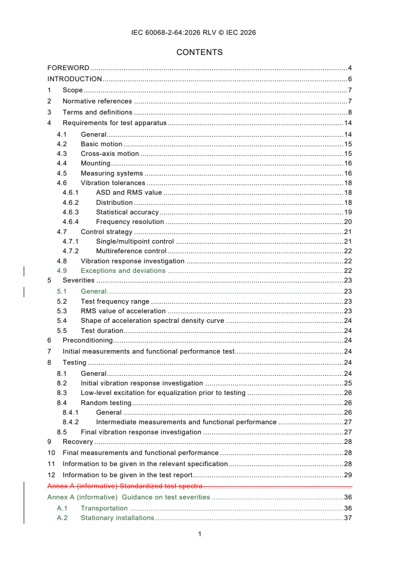
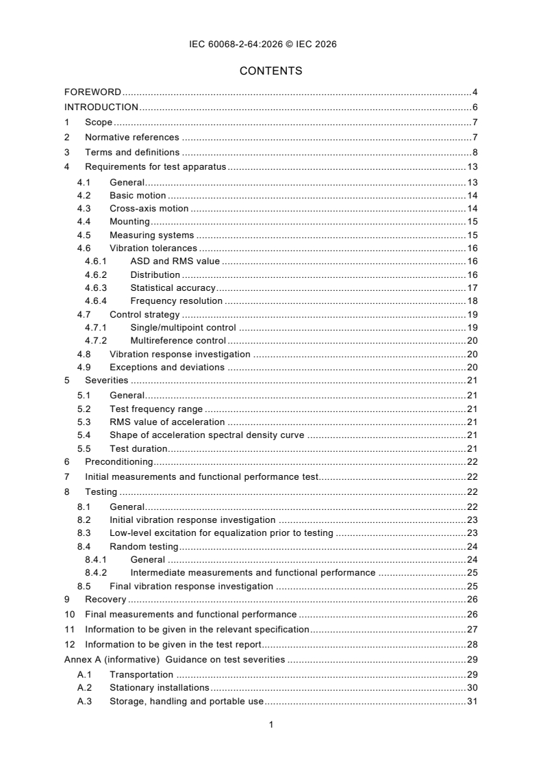
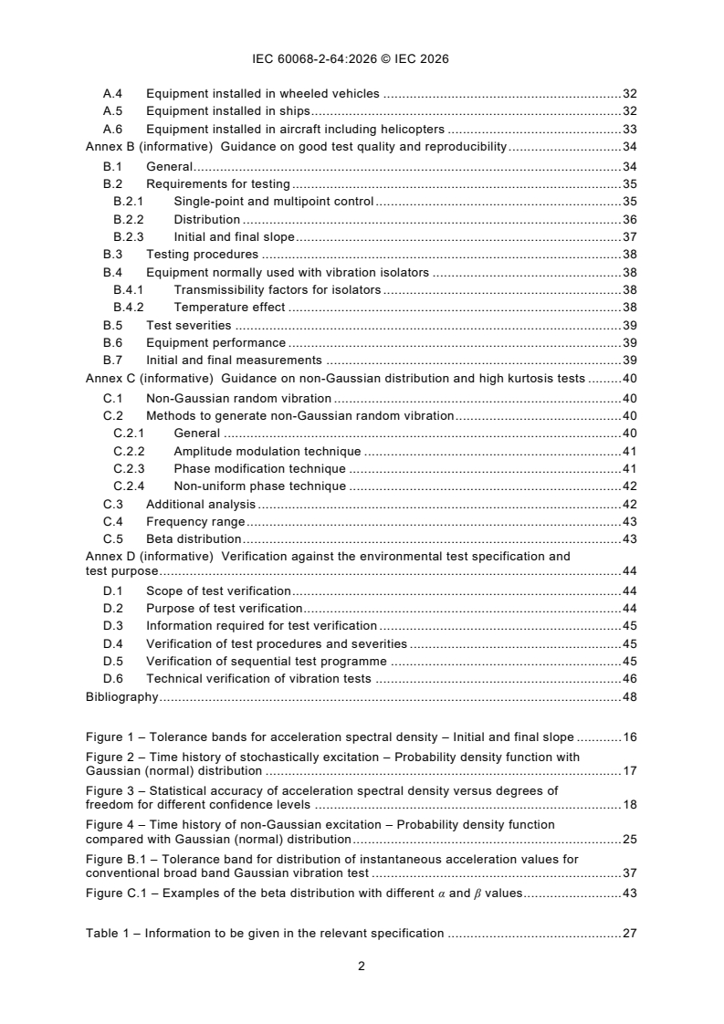
CONTENTS
FOREWORD . 4
INTRODUCTION . 6
1 Scope . 7
2 Normative references . 7
3 Terms and definitions . 8
4 Requirements for test apparatus . 14
4.1 General . 14
4.2 Basic motion . 15
4.3 Cross-axis motion . 15
4.4 Mounting . 16
4.5 Measuring systems . 16
4.6 Vibration tolerances . 18
4.6.1 ASD and RMS value . 18
4.6.2 Distribution . 18
4.6.3 Statistical accuracy . 19
4.6.4 Frequency resolution . 20
4.7 Control strategy . 21
4.7.1 Single/multipoint control . 21
4.7.2 Multireference control . 22
4.8 Vibration response investigation . 22
4.9 Exceptions and deviations . 22
5 Severities . 23
5.1 General . 23
5.2 Test frequency range . 23
5.3 RMS value of acceleration . 23
5.4 Shape of acceleration spectral density curve . 24
5.5 Test duration. 24
6 Preconditioning . 24
7 Initial measurements and functional performance test. 24
8 Testing . 24
8.1 General . 24
8.2 Initial vibration response investigation . 25
8.3 Low-level excitation for equalization prior to testing . 26
8.4 Random testing . 26
8.4.1 General . 26
8.4.2 Intermediate measurements and functional performance . 27
8.5 Final vibration response investigation . 27
9 Recovery . 28
10 Final measurements and functional performance . 28
11 Information to be given in the relevant specification . 28
12 Information to be given in the test report. 29
Annex A (informative) Standardized test spectra .
Annex A (informative) Guidance on test severities . 36
A.1 Transportation . 36
A.2 Stationary installations . 37
A.3 Storage, handling and portable use . 38
A.4 Equipment installed in wheeled vehicles . 39
A.5 Equipment installed in ships . 39
A.6 Equipment installed in aircraft including helicopters . 40
Annex B (informative) Guidance on good test quality and reproducibility . 41
B.1 General . 41
B.2 Requirements for testing . 42
B.2.1 Single-point and multipoint control . 42
B.2.2 Distribution . 43
B.2.3 Initial and final slope . 44
B.3 Testing procedures . 45
B.4 Equipment normally used with vibration isolators . 45
B.4.1 Transmissibility factors for isolators . 45
B.4.2 Temperature effect . 45
B.5 Test severities . 46
B.6 Equipment performance . 46
B.7 Initial and final measurements . 46
Annex C (informative) Guidance on non-Gaussian distribution and high kurtosis tests . 47
C.1 Non-Gaussian random vibration . 47
C.2 Methods to generate non-Gaussian random vibration . 47
C.2.1 General . 47
C.2.2 Amplitude modulation technique . 48
C.2.3 Phase modification technique . 48
C.2.4 Non-uniform phase technique . 49
C.3 Additional analysis . 49
C.4 Frequency range . 50
C.5 Beta distribution . 50
Annex D (informative) Verification against the environmental test specification and
test purpose . 51
D.1 Scope of test verification . 51
D.2 Purpose of test verification . 51
D.3 Information required for test verification . 52
D.4 Verification of test procedures and severities . 52
D.5 Verification of sequential test programme . 52
D.6 Technical verification of vibration tests . 53
Bibliography . 55
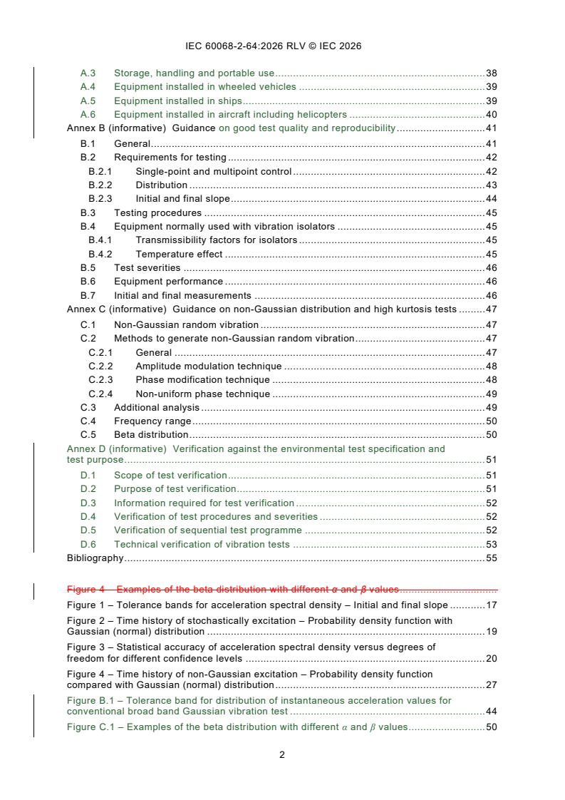
Figure 4 – Examples of the beta distribution with different α and β values .
Figure 1 – Tolerance bands for acceleration spectral density – Initial and final slope . 17
Figure 2 – Time history of stochastically excitation – Probability density function with
Gaussian (normal) distribution . 19
Figure 3 – Statistical accuracy of acceleration spectral density versus degrees of
freedom for different confidence levels . 20
Figure 4 – Time history of non-Gaussian excitation – Probability density function
compared with Gaussian (normal) distribution . 27
Figure B.1 – Tolerance band for distribution of instantaneous acceleration values for
conventional broad band Gaussian vibration test . 44
Figure C.1 – Examples of the beta distribution with different α and β values . 50
Table 1 – Information to be given in the relevant specification . 28
Table 2 – Information to be given in the test report . 29
INTERNATIONAL ELECTROTECHNICAL COMMISSION
____________
Environmental testing -
Part 2-64: Tests - Test Fh: Vibration, broadband random and guidance
FOREWORD
1) The International Electrotechnical Commission (IEC) is a worldwide organization for standardization comprising
all national electrotechnical committees (IEC National Committees). The object of IEC is to promote international
co-operation on all questions concerning standardization in the electrical and electronic fields. To this end and
in addition to other activities, IEC publishes International Standards, Technical Specifications, Technical Reports,
Publicly Available Specifications (PAS) and Guides (hereafter referred to as "IEC Publication(s)"). Their
preparation is entrusted to technical committees; any IEC National Committee interested in the subject dealt with
may participate in this preparatory work. International, governmental and non-governmental organizations liaising
with the IEC also participate in this preparation. IEC collaborates closely with the International Organization for
Standardization (ISO) in accordance with conditions determined by agreement between the two organizations.
2) The formal decisions or agreements of IEC on technical matters express, as nearly as possible, an international
consensus of opinion on the relevant subjects since each technical committee has representation from all
interested IEC National Committees.
3) IEC Publications have the form of recommendations for international use and are accepted by IEC National
Committees in that sense. While all reasonable efforts are made to ensure that the technical content of IEC
Publications is accurate, IEC cannot be held responsible for the way in which they are used or for any
misinterpretation by any end user.
4) In order to promote international uniformity, IEC National Committees undertake to apply IEC Publications
transparently to the maximum extent possible in their national and regional publications. Any divergence between
any IEC Publication and the corresponding national or regional publication shall be clearly indicated in the latter.
5) IEC itself does not provide any attestation of conformity. Independent certification bodies provide conformity
assessment services and, in some areas, access to IEC marks of conformity. IEC is not responsible for any
services carried out by independent certification bodies.
6) All users should ensure that they have the latest edition of this publication.
7) No liability shall attach to IEC or its directors, employees, servants or agents including individual experts and
members of its technical committees and IEC National Committees for any personal injury, property damage or
other damage of any nature whatsoever, whether direct or indirect, or for costs (including legal fees) and
expenses arising out of the publication, use of, or reliance upon, this IEC Publication or any other IEC
Publications.
8) Attention is drawn to the Normative references cited in this publication. Use of the referenced publications is
indispensable for the correct application of this publication.
9) IEC draws attention to the possibility that the implementation of this document may involve the use of (a)
patent(s). IEC takes no position concerning the evidence, validity or applicability of any claimed patent rights in
respect thereof. As of the date of publication of this document, IEC had not received notice of (a) patent(s), which
may be required to implement this document. However, implementers are cautioned that this may not represent
the latest information, which may be obtained from the patent database available at https://patents.iec.ch. IEC
shall not be held responsible for identifying any or all such patent rights.
This redline version of the official IEC Standard allows the user to identify the changes made
to the previous edition IEC 60068-2-64:2008+AMD1:2019 CSV. A vertical bar appears in the
margin wherever a change has been made. Additions are in green text, deletions are in
strikethrough red text.
IEC 60068-2-64 has been prepared by IEC technical committee 104: Environmental conditions,
classification and methods of test. It is an International Standard.
This document has been given the status of a horizontal basic safety document in accordance
with the ISO/IEC Directives, Part 1.
This third edition cancels and replaces the second edition, published in 2008, and
Amendment 1:2019. This edition constitutes a technical revision.
This edition includes the following significant technical changes with respect to the previous
edition:
a) update of Annex A with references to examples;
b) introduction of an organizational deviation treatment;
c) clarification on requirements.
The text of this International Standard is based on the following documents:
Draft Report on voting
104/1190/FDIS 104/1214/RVD
Full information on the voting for its approval can be found in the report on voting indicated in
the above table.
The language used for the development of this International Standard is English.
This document was drafted in accordance with ISO/IEC Directives, Part 2, and developed in
accordance with ISO/IEC Directives, Part 1 and ISO/IEC Directives, IEC Supplement, available
at www.iec.ch/members_experts/refdocs. The main document types developed by IEC are
described in greater detail at www.iec.ch/publications.
A list of all the parts in the IEC 60068 series, under the general title Environmental testing, can
be found on the IEC website.
The committee has decided that the contents of this document will remain unchanged until the
stability date indicated on the IEC website under webstore.iec.ch in the data related to the
specific document. At this date, the document will be
– reconfirmed,
– withdrawn, or
– revised.
INTRODUCTION
This part of IEC 60068 deals with broadband random vibration testing intended for general
application to components, equipment and other products, hereinafter referred to as
"specimens", that may can be subjected to vibrations of a stochastic nature. The methods and
techniques in this document are based on digital control of random vibration. It permits the
introduction of variations to suit individual cases if these are prescribed required by the relevant
specification.
Compared with most other vibration tests, test Fh is not based on deterministic but on statistical
techniques. Broad-band random vibration testing is therefore described in terms of probability
and statistical averages.
It is emphasized that random testing always demands a certain degree of engineering
judgement, and both equipment supplier and purchaser as well as the test house should be
fully aware of this fact. The writer of the relevant specification is expected to select the testing
procedure and the values of severity appropriate to the specimen and its use.
The test method is based primarily on the use of an electrodynamic or a servo-hydraulic
vibration generator with an associated computer-based control system relying on measurement
sensors used as a vibration testing system.
The traditional general-purpose broad-band random vibration test utilizes waveforms with a
Gaussian distribution of amplitudes. However, when so specified, this test procedure can also
be utilized with random vibration tests with a non-Gaussian distribution of amplitudes. Such
tests are sometimes alternatively known as "high kurtosis tests".
Annex A and Annex B are informative annexes giving reference to examples of test spectra for
different environmental conditions and a list of details to be considered for inclusion in
specifications and guidance.
Annex C is an informative annex giving information on non-Gaussian distribution/high kurtosis
tests.
Annex D is an informative annex giving guidance on technical measures of verification that the
intended test purpose is achieved by the test.
1 Scope
This part of IEC 60068 demonstrates the adequacy of a specimen to resist dynamic loads
without unacceptable degradation of its functional and structural integrity (or either of them)
when subjected to the specified random vibration test requirements.
Broadband random vibration may can be used to identify accumulated stress effects and the
resulting mechanical weakness and degradation in the specified performance. This information,
in conjunction with the relevant specification, may can be used to assess the acceptability of
specimens.
This document is applicable to specimens which may can be subjected to vibration of a
stochastic nature resulting from transportation or operational environments, for example, in
aircraft, space vehicles and land vehicles. It is primarily intended for unpackaged specimens,
and for items in their transportation container when the latter may can be considered as part of
the specimen itself. However, if the item is packaged, then the item itself is referred to as a
product, and the item and its packaging together are referred to as a test specimen. This
document may can be used in conjunction with IEC 60068-2-47:2005, for testing packaged
products.
If the specimens are subjected to vibration of a combination of random and deterministic nature
resulting from transportation or real-life environments, for example, in aircraft, space vehicles
and for items in their transportation container, it is possible that testing with pure random may
is not be sufficient. See IEC 60068-3-8:2003 for estimating the dynamic vibration environment
of the specimen and based on that, selecting the appropriate test method.
Although primarily intended for electrotechnical specimens, this document is not restricted to
them and may can be used in other fields where desired (see Annex A).
This document has the status of a horizontal basic safety publication in accordance with IEC
Guide 108.
2 Normative references
The following documents are referred to in the text in such a way that some or all of their content
constitutes requirements of this document. For dated references, only the edition cited applies.
For undated references, the latest edition of the referenced document (including any
amendments) applies.
IEC 60050-300: International Electrotechnical Vocabulary – Electrical and electronic
measurements and measuring instruments – Part 311: General terms relating to measurements
– Part 312: General terms relating to electrical measurements – Part 313: Types of electrical
measuring instruments – Part 314: Specific terms according to the type of instrument
IEC 60068-1, Environmental testing - Part 1: General and guidance
IEC 60068-2-6:2007, Environmental testing - Part 2-6: Tests - Test Fc: Vibration (sinusoidal)
IEC 60068-2-47:2005, Environmental testing - Part 2-47: Test - Mounting of specimens for
vibration, impact and similar dynamic tests
IEC 60068-3-8:2003, Environmental testing – Part 3-8: Supporting documentation and guidance
– Selecting amongst vibration tests
IEC 60068-5-2, Environmental testing - Part 5-2: Guide to drafting of test methods - Terms and
definitions
IEC 60721-3 (all parts), Classification of environmental conditions – Part 3: Classification of
groups of environmental parameters and their severities
IEC Guide 104, The preparation of safety publications and the use of basic safety publications
and group safety publications
ISO 2041: Vibration and shock – Vocabulary
3 Terms and definitions
For the purposes of this document, the terms and definitions given in IEC 60068-1,
IEC 60068-2-6, IEC 60068-5-2 and the following apply.
NOTE The terms used are generally defined in IEC 60050-300, IEC 60068-1, IEC 60068-2-6, and IEC 60068-5-2
and ISO 2041. If a definition from one of those sources is included here, the derivation is indicated and departures
from the definitions in those sources are also indicated.
ISO and IEC maintain terminology databases for use in standardization at the following
addresses:
– IEC Electropedia: available at https://www.electropedia.org/
– ISO Online browsing platform: available at https://www.iso.org/obp
3.1
cross-axis motion
motion not in the direction of the stimulus and which is generally specified in the two axes
orthogonal to the direction of the stimulus
Note 1 to entry: The cross-axis motion should be measured close to the fixing points.
3.2
actual motion
motion represented by the wideband signal returned from the reference point transducer
3.3
fixing point
part of the specimen in contact with the fixture or vibration table at a point where the specimen
is normally fastened in service
Note 1 to entry: If a part of the real mounting structure is used as the fixture, the fixing points are taken as those of
the mounting structure and not of the specimen.
Note 2 to entry: Where the specimen consists of a packaged product, the fixing point can be interpreted as the
surface of the specimen which is in contact with the vibration table.
3.4
control methods
3.4.1
single point control
control method using the signal from the transducer at the reference point in order to maintain
this point at the specified vibration level
3.4.2
multipoint control
control method using the signals from each of the transducers at the checkpoints
Note 1 to entry: The signals are either continuously averaged arithmetically or processed by using comparison
techniques, depending upon the relevant specification. See also 3.13.
3.5
g
n
standard acceleration due to the earth's gravity, which itself varies with altitude and
geographical latitude
Note 1 to entry: For the purposes of this document, the value of g is rounded up to the nearest whole number, that
n
is 10 m/s .
3.6
measuring points
specific points at which data are gathered for conducting the test
Note 1 to entry: The measuring points are of three types, as defined in 3.7 to 3.9.
3.7
checkpoint
point located on the fixture, on the vibration table or on the specimen as close as possible to
one of its fixing points, and in any case, rigidly connected to it
Note 1 to entry: A number of checkpoints are used as a means of ensuring that the test requirements are satisfied.
NOTE 2 If four or fewer fixing points exist, each is used as a checkpoint. For packaged products, where a fixing
point may be interpreted as the packaging surface in contact with the vibration table, one checkpoint may be used,
provided that there are no effects due to resonances of the vibration table or the mounting structure in the frequency
range specified for the test. If this is the case, multipoint control may be necessary, but see also NOTE 3. If more
than four fixing points exist, four representative fixing points will be defined in the relevant specification to be used
as checkpoints.
NOTE 3 In special cases, for example for large or complex specimens, the checkpoints will be prescribed by the
relevant specification if not close to the fixing points.
NOTE 4 Where a large number of small specimens are mounted on one fixture, or in the case of a small specimen
with a number of fixing points, a single checkpoint (that is the reference point) may be selected for the derivation of
the control signal. This signal is then related to the fixture rather than to the fixing points of the specimen(s). This
procedure is only valid when the lowest resonance frequency of the loaded fixture is well above the upper frequency
of the test.
3.8
reference point
point, chosen from amongst the checkpoints, whose signal is used to
control the test, such that the requirements of this document are satisfied
3.9
fictitious reference point
point, derived from multiple checkpoints either manually or automatically,
the result of which is used to control the test so that the requirements of this document are
satisfied
3.10
response points
specific points on the specimen from which data is gathered for the purpose of the vibration
response investigation
Note 1 to entry: The response points are not the same as checkpoints or reference points.
3.11
preferred testing axes
three (usually) orthogonal axes that correspond to the most vulnerable axes of the specimen
Note 1 to entry: The selection of the preferred testing axes can depend on the specimen's design and the sub-
components inside; the preferred testing axes are not always orthogonal. The in-service mounting orientation of the
specimen can also play a role in the selection of the preferred testing axes. See also IEC 60068-2-86 for more
information on multi-axis testing.
3.12
sampling frequency
number of discrete magnitude values taken per second to record or represent a time-history in
a digital form
3.13
multipoint control strategy
method for calculating the reference control signal when using multipoint control
Note 1 to entry: Different frequency domain control strategies are discussed to in 4.7.1.
3.14
averaging
process of determining the control acceleration spectral density formed from the arithmetic
average of the acceleration spectral densities at each frequency line of more than one
checkpoint
3.15
extremal (maximum or minimum)
process of determining the control acceleration spectral density formed from the maximum or
minimum acceleration spectral density at each frequency line of more than one checkpoint
3.16
crest factor
ratio of the peak value to the RMS value of the time history
[ISO 2041]
3.17
–3 dB bandwidth
frequency bandwidth between two points in a frequency response function which are at 0,707
of the maximum response when associated with a single resonance peak
Note 1 to entry: The –3 dB bandwidth can be applied to power or field dimensions, but the chosen dimension is to
be given.
3.18
acceleration spectral density
ASD
mean-square value of that part of an acceleration signal passed by a narrow-band filter of a
centre frequency, per unit bandwidth, in the limit as the bandwidth approaches zero and the
averaging time approaches infinity
3.19
control acceleration spectral density
acceleration spectral density measured at the reference point or the fictitious reference point
3.20
control loop
control system loop
sum of the following actions:
– digitizing the analogue waveform of the signal derived from the reference point or fictitious
reference point;
– performing the necessary processing;
– producing an updated analogue drive waveform to the vibration system power amplifier
(see Clause B.1)
Note 1 to entry: Subsystems in the control system loop and steps in the signal processing chain can be
– a transducer (measurement instrument transferring the physical quantity to be measured – usually kinetic like
acceleration – to an electric signal), feeding to
– a signal conditioning, which can be included in the controller (power supply, AC-coupling) or the transducer
(charge amplifier), feeding to
– a controller (producing a defined output signal to achieve a certain wanted vibration environment), feeding drive
signal to
– a power amplifier (including further control loops and signal processing), feeding to
– a shaker (transfer from electric actuation power to mechanical movement and force), movement measurement
by transducer.
3.21
drive signal clipping (see also Figure 1)
limitation of the maximum crest factor of imposed on the drive signal within the effective
frequency range
Note 1 to entry: The drive signal clipping is processed to apply the required crest factor (3.16) to the drive signal(s)
produced by the digital control system.
3.22
effective frequency range
frequency range of measurement and control between 0,5 times f and 2,0 times f of the test
1 2
frequency range
SEE Figure 1.
Note 1 to entry: Due to initial and final slope, the effective frequency range is higher than the test frequency range
between f and f .
1 2
3.23
error in acceleration spectral density
difference between the specified acceleration spectral density and the control acceleration
spectral density
3.24
equalization
minimization of the error in acceleration spectral density
3.25
final slope
part of the specified acceleration spectral density above f
SEE Figure 1.
3.26
frequency resolution
B
e
width of the frequency intervals in the acceleration spectral density
Note 1 to entry: The frequency resolution is expressed in Hertz.
Note 2 to entry: The frequency resolution is equal to the reciprocal of the record block length (T) in digital analysis;
the number of frequency lines is equal to the number of intervals in a given frequency range.
3.27
indicated acceleration spectral density
estimate of the true acceleration spectral density read from the analyser presentation distorted
by the instrument error and the random error
3.28
initial slope
part of the specified acceleration spectral density below f
SEE Figure 1.
3.29
instrument error
error associated with each analogue item of the input to the control system and control system
analogue items
3.30
random error
error in acceleration spectral density changing from one estimate to another of the acceleration
spectral density because of the limitation of averaging time and filter bandwidth in practice
Note 1 to entry: With an infinite averaging time, the error would converge towards zero.
3.31
record
collection of equally spaced data points in the time domain that are used
in the calculation of the fast Fourier transform
3.32
reproducibility
closeness of the agreement between the results of measurements of the same value of the
same quantity, where the individual measurements are made
– by different methods,
– with different measuring instruments,
– with different signal generation,
– by different observers,
– in different laboratories,
– after intervals of time which are long compared with the duration of a single measurement,
and
– under different customary conditions of use of the instruments employed
Note 1 to entry: The term "reproducible" also applies to the case where only certain of the preceding conditions are
taken into account.
[IEC 60050-300, modified]
3.33
root-mean-square value
RMS value
square root of the average
of the squared values of all functions over the total frequency interval f and f
1 2
SEE Figure 2.
3.34
standard deviation
σ
RMS value of the deviation of a random time history from a mean value
SEE Figure 2.
Note 1 to entry: In vibration theory, the mean value of vibration is equal to zero; therefore, for a random time history,
the standard deviation is equal to the RMS value. For non-gaussian distribution, see Annex C.
3.35
statistical accuracy
ratio of true acceleration spectral density to indicated acceleration spectral density
3.36
statistical degrees of freedom
DOF
effective number derived from the frequency resolution and the effective averaging time for
estimation of acceleration spectral density of random data with a time-averaging technique, the
effective number of statistical degrees of freedom is derived from the frequency resolution and
the effective averaging time
SEE Figure 3.
3.37
test frequency range
frequency range between f and f in which the ASD is constant or shaped as given in the
1 2
relevant specification
SEE Figure 1.
3.38
true acceleration spectral density
acceleration spectral density of the random signal acting on the specimen
3.39
kurtosis
μ
th
4 statistical moment, which provides a measure of the shape of an amplitude distribution
Note 1 to entry: Typically, a waveform with Gaussian distribution will have a kurtosis of 3, if considered over an
infinite period.
Note 2 to entry: Kurtosis is given by:
N
μ x−x.
( )
∑ i
N
σ
i=1
where
σ is the standard deviation of the N values which describe the waveform;
x are individual values representing the waveform described by N such values;
i
is the mean value of the N values which describe the waveform.
x
3.40
skewness
μ
rd
3 statistical moment, which provides a measure of non-symmetry of an amplitude distribution
Note 1 to entry: Typically, a waveform with Gaussian distribution will have a skewness of 0, if considered over an
infinite period.
Note 2 to entry: Skewness is given by:
N
μ x−x.
( )
∑ i
N
σ
i=1
where
σ is the standard deviation of the N values which describe the waveform;
x are individual values representing the waveform described by N such values;
i
=
=
x
is the mean value of the N values which describe the waveform.
3.41
beta distribution
family of continuous probability distributions defined on the interval [0, 1] parametrized by two
positive shape parameters, denoted by α and β, that appear as exponents of the random
variable and control the shape of the distribution
SEE: Figure 4.
Figure 4 – Examples of the beta distribution with different α and β values
4 Requirements for test apparatus
4.1 General
The required characteristics apply to the complete vibration system, which includes the power
amplifier, vibrator, test fixture, specimen and control system when loaded for testing.
The standardized test method consists of the following test sequence normally applied in each
of the mutually perpendicular axes of the test specimen:
a) an initial vibration response investigation, with low level sinusoidal excitation, or low-level
random excitation (see 8.2);
b) the random excitation as the mechanical load or stress test;
c) a final vibration response investigation to compare the results with the initial one and to
detect possible mechanical failures due to a change of the dynamic behaviour (see 8.2 and
8.5).
Where the dynamic behaviour is known, and it is not considered relevant, or sufficient data can
be gathered during the test at full level, it is possible that the relevant specification may does
not require pre and post-test vibration response investigations.
For non-Gaussian testing, the test apparatus shall be able to produce a signal with a specified
probability distribution and crest factor. Generally, non-Gaussian random vibration testing
requires shaker and amplifier systems that are designed for Gaussian random vibrations but
with increased crest factor capabilities.
4.2 Basic motion
The basic motion of the fixing points of the specimen shall be prescribed specified by the
relevant specification. and measured as actual motion. The fixing points shall should have
substantially identical motions in phase and amplitude (within the requirements set here and in
the test specification) and shall be rectilinear relative to the direction of excitation. If
substantially identical motions are difficult to achieve, then a multipoint control strategy shall
be used. Deviations between the excitation points shall be monitored and documented.
Definition and guidance on appropriate fixtures are found in IEC 60068-2-47 (mounting). For
technical measures to verify that the test purpose is still fulfilled, see Annex D.
NOTE 1 For large structures and a high frequency range, for example, 20 Hz to 2 000 Hz, the dynamics of the test
specimen is likely to require multipoint control.
NOTE 2 If four or fewer fixing points exist, each is used as a checkpoint. For packaged products, where a fixing
point can be interpreted as the packaging surface in contact with the vibration table, one checkpoint can be used,
provided that there are no effects due to resonances of the vibration table or the mounting structure in the frequency
range specified for the test. If this is the case, multipoint control can be recommended but see also Note 3. If more
than four fixing points exist, four representative fixing points will be defined in the relevant specification to be used
as checkpoints.
NOTE 3 In special cases, for example, for large or complex specimens, the checkpoints will be specified by the
relevant specification if not close to the fixing points.
NOTE 4 Where a large number of small specimens are mounted on one fixture, or in the case of a small specimen
with a number of fixing points, a single checkpoint (that is the reference point) can be selected for the derivation of
the control signal. This signal is then related to the fixture rather than to the fixing points of the specimen(s). This
procedure is only valid when the lowest resonance frequency of the loaded fixture is well above the upper frequency
of the test.
4.3 Cross-axis motion
Unless specified otherwise by the relevant specification, cross-axis motion should shall be
checked, if required by the relevant specification, either before the test is applied by conducting
a sine or random investigation at a level prescribed specified by the relevant specification, or
during testing by utilising additional monitoring channels in the two perpendicular axes.
If not specified otherwise in referencing standards or contractual agreements, the following
applies.
The ASD value of each frequency at the checkpoints in both axes perpendicular to the specified
axis shall not exceed the specified ASD values above 500 Hz and shall not exceed –3 dB of the
specified ASD values below 500 Hz. The total RMS value of acceleration in both axes
perpendicular to the specified axis shall not exceed 50 %
...
IEC 60068-2-64 ®
Edition 3.0 2026-10
INTERNATIONAL
STANDARD
BASIC SAFETY PUBLICATION
HORIZONTAL PUBLICATION
Environmental testing -
Part 2-64: Tests - Test Fh: Vibration, broadband random and guidance
ICS 19.040 ISBN 978-2-8327-1531-4
All rights reserved. Unless otherwise specified, no part of this publication may be reproduced or utilized in any form or
by any means, electronic or mechanical, including photocopying and microfilm, without permission in writing from either
IEC or IEC's member National Committee in the country of the requester. If you have any questions about IEC copyright
or have an enquiry about obtaining additional rights to this publication, please contact the address below or your local
IEC member National Committee for further information.
IEC Secretariat Tel.: +41 22 919 02 11
3, rue de Varembé info@iec.ch
CH-1211 Geneva 20 www.iec.ch
Switzerland
About the IEC
The International Electrotechnical Commission (IEC) is the leading global organization that prepares and publishes
International Standards for all electrical, electronic and related technologies.
About IEC publications
The technical content of IEC publications is kept under constant review by the IEC. Please make sure that you have the
latest edition, a corrigendum or an amendment might have been published.
IEC publications search - IEC Products & Services Portal - products.iec.ch
webstore.iec.ch/advsearchform Discover our powerful search engine and read freely all the
The advanced search enables to find IEC publications by a publications previews, graphical symbols and the glossary.
variety of criteria (reference number, text, technical With a subscription you will always have access to up to date
committee, …). It also gives information on projects, content tailored to your needs.
replaced and withdrawn publications.
Electropedia - www.electropedia.org
The world's leading online dictionary on electrotechnology,
IEC Just Published - webstore.iec.ch/justpublished
Stay up to date on all new IEC publications. Just Published containing more than 22 500 terminological entries in English
details all new publications released. Available online and and French, with equivalent terms in 25 additional languages.
once a month by email. Also known as the International Electrotechnical Vocabulary
(IEV) online.
IEC Customer Service Centre - webstore.iec.ch/csc
If you wish to give us your feedback on this publication or
need further assistance, please contact the Customer
Service Centre: sales@iec.ch.
CONTENTS
FOREWORD . 4
INTRODUCTION . 6
1 Scope . 7
2 Normative references . 7
3 Terms and definitions . 8
4 Requirements for test apparatus . 13
4.1 General . 13
4.2 Basic motion . 14
4.3 Cross-axis motion . 14
4.4 Mounting . 15
4.5 Measuring systems . 15
4.6 Vibration tolerances . 16
4.6.1 ASD and RMS value . 16
4.6.2 Distribution . 16
4.6.3 Statistical accuracy . 17
4.6.4 Frequency resolution . 18
4.7 Control strategy . 19
4.7.1 Single/multipoint control . 19
4.7.2 Multireference control . 20
4.8 Vibration response investigation . 20
4.9 Exceptions and deviations . 20
5 Severities . 21
5.1 General . 21
5.2 Test frequency range . 21
5.3 RMS value of acceleration . 21
5.4 Shape of acceleration spectral density curve . 21
5.5 Test duration. 21
6 Preconditioning . 22
7 Initial measurements and functional performance test. 22
8 Testing . 22
8.1 General . 22
8.2 Initial vibration response investigation . 23
8.3 Low-level excitation for equalization prior to testing . 23
8.4 Random testing . 24
8.4.1 General . 24
8.4.2 Intermediate measurements and functional performance . 25
8.5 Final vibration response investigation . 25
9 Recovery . 26
10 Final measurements and functional performance . 26
11 Information to be given in the relevant specification . 27
12 Information to be given in the test report. 28
Annex A (informative) Guidance on test severities . 29
A.1 Transportation . 29
A.2 Stationary installations . 30
A.3 Storage, handling and portable use . 31
A.4 Equipment installed in wheeled vehicles . 32
A.5 Equipment installed in ships . 32
A.6 Equipment installed in aircraft including helicopters . 33
Annex B (informative) Guidance on good test quality and reproducibility . 34
B.1 General . 34
B.2 Requirements for testing . 35
B.2.1 Single-point and multipoint control . 35
B.2.2 Distribution . 36
B.2.3 Initial and final slope . 37
B.3 Testing procedures . 38
B.4 Equipment normally used with vibration isolators . 38
B.4.1 Transmissibility factors for isolators . 38
B.4.2 Temperature effect . 38
B.5 Test severities . 39
B.6 Equipment performance . 39
B.7 Initial and final measurements . 39
Annex C (informative) Guidance on non-Gaussian distribution and high kurtosis tests . 40
C.1 Non-Gaussian random vibration . 40
C.2 Methods to generate non-Gaussian random vibration . 40
C.2.1 General . 40
C.2.2 Amplitude modulation technique . 41
C.2.3 Phase modification technique . 41
C.2.4 Non-uniform phase technique . 42
C.3 Additional analysis . 42
C.4 Frequency range . 43
C.5 Beta distribution . 43
Annex D (informative) Verification against the environmental test specification and
test purpose . 44
D.1 Scope of test verification . 44
D.2 Purpose of test verification . 44
D.3 Information required for test verification . 45
D.4 Verification of test procedures and severities . 45
D.5 Verification of sequential test programme . 45
D.6 Technical verification of vibration tests . 46
Bibliography . 48
Figure 1 – Tolerance bands for acceleration spectral density – Initial and final slope . 16
Figure 2 – Time history of stochastically excitation – Probability density function with
Gaussian (normal) distribution . 17
Figure 3 – Statistical accuracy of acceleration spectral density versus degrees of
freedom for different confidence levels . 18
Figure 4 – Time history of non-Gaussian excitation – Probability density function
compared with Gaussian (normal) distribution . 25
Figure B.1 – Tolerance band for distribution of instantaneous acceleration values for
conventional broad band Gaussian vibration test . 37
Figure C.1 – Examples of the beta distribution with different α and β values . 43
Table 1 – Information to be given in the relevant specification . 27
Table 2 – Information to be given in the test report . 28
INTERNATIONAL ELECTROTECHNICAL COMMISSION
____________
Environmental testing -
Part 2-64: Tests - Test Fh: Vibration, broadband random and guidance
FOREWORD
1) The International Electrotechnical Commission (IEC) is a worldwide organization for standardization comprising
all national electrotechnical committees (IEC National Committees). The object of IEC is to promote international
co-operation on all questions concerning standardization in the electrical and electronic fields. To this end and
in addition to other activities, IEC publishes International Standards, Technical Specifications, Technical Reports,
Publicly Available Specifications (PAS) and Guides (hereafter referred to as "IEC Publication(s)"). Their
preparation is entrusted to technical committees; any IEC National Committee interested in the subject dealt with
may participate in this preparatory work. International, governmental and non-governmental organizations liaising
with the IEC also participate in this preparation. IEC collaborates closely with the International Organization for
Standardization (ISO) in accordance with conditions determined by agreement between the two organizations.
2) The formal decisions or agreements of IEC on technical matters express, as nearly as possible, an international
consensus of opinion on the relevant subjects since each technical committee has representation from all
interested IEC National Committees.
3) IEC Publications have the form of recommendations for international use and are accepted by IEC National
Committees in that sense. While all reasonable efforts are made to ensure that the technical content of IEC
Publications is accurate, IEC cannot be held responsible for the way in which they are used or for any
misinterpretation by any end user.
4) In order to promote international uniformity, IEC National Committees undertake to apply IEC Publications
transparently to the maximum extent possible in their national and regional publications. Any divergence between
any IEC Publication and the corresponding national or regional publication shall be clearly indicated in the latter.
5) IEC itself does not provide any attestation of conformity. Independent certification bodies provide conformity
assessment services and, in some areas, access to IEC marks of conformity. IEC is not responsible for any
services carried out by independent certification bodies.
6) All users should ensure that they have the latest edition of this publication.
7) No liability shall attach to IEC or its directors, employees, servants or agents including individual experts and
members of its technical committees and IEC National Committees for any personal injury, property damage or
other damage of any nature whatsoever, whether direct or indirect, or for costs (including legal fees) and
expenses arising out of the publication, use of, or reliance upon, this IEC Publication or any other IEC
Publications.
8) Attention is drawn to the Normative references cited in this publication. Use of the referenced publications is
indispensable for the correct application of this publication.
9) IEC draws attention to the possibility that the implementation of this document may involve the use of (a)
patent(s). IEC takes no position concerning the evidence, validity or applicability of any claimed patent rights in
respect thereof. As of the date of publication of this document, IEC had not received notice of (a) patent(s), which
may be required to implement this document. However, implementers are cautioned that this may not represent
the latest information, which may be obtained from the patent database available at https://patents.iec.ch. IEC
shall not be held responsible for identifying any or all such patent rights.
IEC 60068-2-64 has been prepared by IEC technical committee 104: Environmental conditions,
classification and methods of test. It is an International Standard.
This document has been given the status of a horizontal basic safety document in accordance
with the ISO/IEC Directives, Part 1.
This third edition cancels and replaces the second edition, published in 2008, and
Amendment 1:2019. This edition constitutes a technical revision.
This edition includes the following significant technical changes with respect to the previous
edition:
a) update of Annex A with references to examples;
b) introduction of an organizational deviation treatment;
c) clarification on requirements.
The text of this International Standard is based on the following documents:
Draft Report on voting
104/1190/FDIS 104/1214/RVD
Full information on the voting for its approval can be found in the report on voting indicated in
the above table.
The language used for the development of this International Standard is English.
This document was drafted in accordance with ISO/IEC Directives, Part 2, and developed in
accordance with ISO/IEC Directives, Part 1 and ISO/IEC Directives, IEC Supplement, available
at www.iec.ch/members_experts/refdocs. The main document types developed by IEC are
described in greater detail at www.iec.ch/publications.
A list of all the parts in the IEC 60068 series, under the general title Environmental testing, can
be found on the IEC website.
The committee has decided that the contents of this document will remain unchanged until the
stability date indicated on the IEC website under webstore.iec.ch in the data related to the
specific document. At this date, the document will be
– reconfirmed,
– withdrawn, or
– revised.
INTRODUCTION
This part of IEC 60068 deals with broadband random vibration testing intended for general
application to components, equipment and other products, hereinafter referred to as
"specimens", that can be subjected to vibrations of a stochastic nature. The methods and
techniques in this document are based on digital control of random vibration. It permits the
introduction of variations to suit individual cases if these are required by the relevant
specification.
Compared with most other vibration tests, test Fh is not based on deterministic but on statistical
techniques. Broad-band random vibration testing is therefore described in terms of probability
and statistical averages.
It is emphasized that random testing always demands a certain degree of engineering
judgement, and both equipment supplier and purchaser as well as the test house should be
fully aware of this fact. The writer of the relevant specification is expected to select the testing
procedure and the values of severity appropriate to the specimen and its use.
The test method is based primarily on the use of an electrodynamic or a servo-hydraulic
vibration generator with an associated computer-based control system relying on measurement
sensors used as a vibration testing system.
The traditional general-purpose broad-band random vibration test utilizes waveforms with a
Gaussian distribution of amplitudes. However, when so specified, this test procedure can also
be utilized with random vibration tests with a non-Gaussian distribution of amplitudes. Such
tests are sometimes alternatively known as "high kurtosis tests".
Annex A and Annex B are informative annexes giving reference to examples of test spectra for
different environmental conditions and a list of details to be considered for inclusion in
specifications and guidance.
Annex C is an informative annex giving information on non-Gaussian distribution/high kurtosis
tests.
Annex D is an informative annex giving guidance on technical measures of verification that the
intended test purpose is achieved by the test.
1 Scope
This part of IEC 60068 demonstrates the adequacy of a specimen to resist dynamic loads
without unacceptable degradation of its functional and structural integrity (or either of them)
when subjected to the specified random vibration test requirements.
Broadband random vibration can be used to identify accumulated stress effects and the
resulting mechanical weakness and degradation in the specified performance. This information,
in conjunction with the relevant specification, can be used to assess the acceptability of
specimens.
This document is applicable to specimens which can be subjected to vibration of a stochastic
nature resulting from transportation or operational environments, for example, in aircraft, space
vehicles and land vehicles. It is primarily intended for unpackaged specimens, and for items in
their transportation container when the latter can be considered as part of the specimen itself.
However, if the item is packaged, then the item itself is referred to as a product, and the item
and its packaging together are referred to as a test specimen. This document can be used in
conjunction with IEC 60068-2-47:2005, for testing packaged products.
If the specimens are subjected to vibration of a combination of random and deterministic nature
resulting from transportation or real-life environments, for example, in aircraft, space vehicles
and for items in their transportation container, it is possible that testing with pure random is not
sufficient. See IEC 60068-3-8:2003 for estimating the dynamic vibration environment of the
specimen and based on that, selecting the appropriate test method.
Although primarily intended for electrotechnical specimens, this document is not restricted to
them and can be used in other fields where desired (see Annex A).
This document has the status of a horizontal basic safety publication in accordance with IEC
Guide 108.
2 Normative references
The following documents are referred to in the text in such a way that some or all of their content
constitutes requirements of this document. For dated references, only the edition cited applies.
For undated references, the latest edition of the referenced document (including any
amendments) applies.
IEC 60068-1, Environmental testing - Part 1: General and guidance
IEC 60068-2-6:2007, Environmental testing - Part 2-6: Tests - Test Fc: Vibration (sinusoidal)
IEC 60068-2-47:2005, Environmental testing - Part 2-47: Test - Mounting of specimens for
vibration, impact and similar dynamic tests
IEC 60068-5-2, Environmental testing - Part 5-2: Guide to drafting of test methods - Terms and
definitions
3 Terms and definitions
For the purposes of this document, the terms and definitions given in IEC 60068-1,
IEC 60068-2-6, IEC 60068-5-2 and the following apply.
ISO and IEC maintain terminology databases for use in standardization at the following
addresses:
– IEC Electropedia: available at https://www.electropedia.org/
– ISO Online browsing platform: available at https://www.iso.org/obp
3.1
cross-axis motion
motion not in the direction of the stimulus and which is generally specified in the two axes
orthogonal to the direction of the stimulus
Note 1 to entry: The cross-axis motion should be measured close to the fixing points.
3.2
actual motion
motion represented by the wideband signal returned from the reference point transducer
3.3
fixing point
part of the specimen in contact with the fixture or vibration table at a point where the specimen
is normally fastened in service
Note 1 to entry: If a part of the real mounting structure is used as the fixture, the fixing points are taken as those of
the mounting structure and not of the specimen.
Note 2 to entry: Where the specimen consists of a packaged product, the fixing point can be interpreted as the
surface of the specimen which is in contact with the vibration table.
3.4
control methods
3.4.1
single point control
control method using the signal from the transducer at the reference point in order to maintain
this point at the specified vibration level
3.4.2
multipoint control
control method using the signals from each of the transducers at the checkpoints
Note 1 to entry: The signals are either continuously averaged arithmetically or processed by using comparison
techniques, depending upon the relevant specification. See also 3.13.
3.5
g
n
standard acceleration due to the earth's gravity, which itself varies with altitude and
geographical latitude
Note 1 to entry: For the purposes of this document, the value of g is rounded up to the nearest whole number, that
n
is 10 m/s .
3.6
measuring points
specific points at which data are gathered for conducting the test
Note 1 to entry: The measuring points are of three types, as defined in 3.7 to 3.9.
3.7
checkpoint
point located on the fixture, on the vibration table or on the specimen as close as possible to
one of its fixing points, and in any case, rigidly connected to it
Note 1 to entry: A number of checkpoints are used as a means of ensuring that the test requirements are satisfied.
3.8
reference point
point, chosen from amongst the checkpoints, whose signal is used to
control the test, such that the requirements of this document are satisfied
3.9
fictitious reference point
point, derived from multiple checkpoints either manually or automatically,
the result of which is used to control the test so that the requirements of this document are
satisfied
3.10
response points
specific points on the specimen from which data is gathered for the purpose of the vibration
response investigation
Note 1 to entry: The response points are not the same as checkpoints or reference points.
3.11
preferred testing axes
three (usually) orthogonal axes that correspond to the most vulnerable axes of the specimen
Note 1 to entry: The selection of the preferred testing axes can depend on the specimen's design and the sub-
components inside; the preferred testing axes are not always orthogonal. The in-service mounting orientation of the
specimen can also play a role in the selection of the preferred testing axes. See also IEC 60068-2-86 for more
information on multi-axis testing.
3.12
sampling frequency
number of discrete magnitude values taken per second to record or represent a time-history in
a digital form
3.13
multipoint control strategy
method for calculating the reference control signal when using multipoint control
Note 1 to entry: Different frequency domain control strategies are discussed to in 4.7.1.
3.14
averaging
process of determining the control acceleration spectral density formed from the arithmetic
average of the acceleration spectral densities at each frequency line of more than one
checkpoint
3.15
extremal
process of determining the control acceleration spectral density formed from the maximum or
minimum acceleration spectral density at each frequency line of more than one checkpoint
3.16
crest factor
ratio of the peak value to the RMS value of the time history
3.17
–3 dB bandwidth
frequency bandwidth between two points in a frequency response function which are at 0,707
of the maximum response when associated with a single resonance peak
Note 1 to entry: The –3 dB bandwidth can be applied to power or field dimensions, but the chosen dimension is to
be given.
3.18
acceleration spectral density
ASD
mean-square value of that part of an acceleration signal passed by a narrow-band filter of a
centre frequency, per unit bandwidth, in the limit as the bandwidth approaches zero and the
averaging time approaches infinity
3.19
control acceleration spectral density
acceleration spectral density measured at the reference point or the fictitious reference point
3.20
control loop
control system
sum of the following actions:
– digitizing the analogue waveform of the signal derived from the reference point or fictitious
reference point;
– performing the necessary processing;
– producing an updated analogue drive waveform to the vibration system power amplifier
(see Clause B.1)
Note 1 to entry: Subsystems in the control system loop and steps in the signal processing chain can be
– a transducer (measurement instrument transferring the physical quantity to be measured – usually kinetic like
acceleration – to an electric signal), feeding to
– a signal conditioning, which can be included in the controller (power supply, AC-coupling) or the transducer
(charge amplifier), feeding to
– a controller (producing a defined output signal to achieve a certain wanted vibration environment), feeding drive
signal to
– a power amplifier (including further control loops and signal processing), feeding to
– a shaker (transfer from electric actuation power to mechanical movement and force), movement measurement
by transducer.
3.21
drive signal clipping
limitation of the maximum crest factor imposed on the drive signal within the effective frequency
range
Note 1 to entry: The drive signal clipping is processed to apply the required crest factor (3.16) to the drive signal(s)
produced by the digital control system.
3.22
effective frequency range
frequency range of measurement and control between 0,5 times f and 2,0 times f of the test
1 2
frequency range
SEE Figure 1.
Note 1 to entry: Due to initial and final slope, the effective frequency range is higher than the test frequency range
between f and f .
1 2
3.23
error in acceleration spectral density
difference between the specified acceleration spectral density and the control acceleration
spectral density
3.24
equalization
minimization of the error in acceleration spectral density
3.25
final slope
part of the specified acceleration spectral density above f
SEE Figure 1.
3.26
frequency resolution
B
e
width of the frequency intervals in the acceleration spectral density
Note 1 to entry: The frequency resolution is expressed in Hertz.
Note 2 to entry: The frequency resolution is equal to the reciprocal of the record block length (T) in digital analysis;
the number of frequency lines is equal to the number of intervals in a given frequency range.
3.27
indicated acceleration spectral density
estimate of the true acceleration spectral density read from the analyser presentation distorted
by the instrument error and the random error
3.28
initial slope
part of the specified acceleration spectral density below f
SEE Figure 1.
3.29
instrument error
error associated with each analogue item of the input to the control system and control system
analogue items
3.30
random error
error in acceleration spectral density changing from one estimate to another because of the
limitation of averaging time and filter bandwidth in practice
Note 1 to entry: With an infinite averaging time, the error would converge towards zero.
3.31
record
collection of equally spaced data points in the time domain that are used
in the calculation of the fast Fourier transform
3.32
reproducibility
closeness of the agreement between the results of measurements of the same value of the
same quantity, where the individual measurements are made
– by different methods,
– with different measuring instruments,
– with different signal generation,
– by different observers,
– in different laboratories,
– after intervals of time which are long compared with the duration of a single measurement,
and
– under different customary conditions of use of the instruments employed
Note 1 to entry: The term "reproducible" also applies to the case where only certain of the preceding conditions are
taken into account.
3.33
root-mean-square value
RMS value
square root of the average
of the squared values of all functions over the total frequency interval f and f
1 2
SEE Figure 2.
3.34
standard deviation
σ
RMS value of the deviation of a random time history from a mean value
SEE Figure 2.
Note 1 to entry: In vibration theory, the mean value of vibration is equal to zero; therefore, for a random time history,
the standard deviation is equal to the RMS value. For non-gaussian distribution, see Annex C.
3.35
statistical accuracy
ratio of true acceleration spectral density to indicated acceleration spectral density
3.36
statistical degrees of freedom
DOF
effective number derived from the frequency resolution and the effective averaging time for
estimation of acceleration spectral density of random data with a time-averaging technique
SEE Figure 3.
3.37
test frequency range
frequency range between f and f in which the ASD is constant or shaped as given in the
1 2
relevant specification
SEE Figure 1.
3.38
true acceleration spectral density
acceleration spectral density of the random signal acting on the specimen
3.39
kurtosis
μ
th
4 statistical moment, which provides a measure of the shape of an amplitude distribution
Note 1 to entry: Typically, a waveform with Gaussian distribution will have a kurtosis of 3, if considered over an
infinite period.
Note 2 to entry: Kurtosis is given by:
N
μ x−x.
( )
4 ∑ i
N
σ
i=1
where
σ is the standard deviation of the N values which describe the waveform;
x are individual values representing the waveform described by N such values;
i
x is the mean value of the N values which describe the waveform.
3.40
skewness
μ
rd
3 statistical moment, which provides a measure of non-symmetry of an amplitude distribution
Note 1 to entry: Typically, a waveform with Gaussian distribution will have a skewness of 0, if considered over an
infinite period.
Note 2 to entry: Skewness is given by:
N
μ x−x.
( )
3 ∑ i
N
σ
i=1
where
σ is the standard deviation of the N values which describe the waveform;
x are individual values representing the waveform described by N such values;
i
x
is the mean value of the N values which describe the waveform.
4 Requirements for test apparatus
4.1 General
The required characteristics apply to the complete vibration system, which includes the power
amplifier, vibrator, test fixture, specimen and control system when loaded for testing.
The standardized test method consists of the following test sequence normally applied in each
of the mutually perpendicular axes of the test specimen:
a) an initial vibration response investigation, with low level sinusoidal excitation, or low-level
random excitation (see 8.2);
b) the random excitation as the mechanical load or stress test;
c) a final vibration response investigation to compare the results with the initial one and to
detect possible mechanical failures due to a change of the dynamic behaviour (see 8.2 and
8.5).
=
=
Where the dynamic behaviour is known, and it is not considered relevant, or sufficient data can
be gathered during the test at full level, it is possible that the relevant specification does not
require pre and post-test vibration response investigations.
For non-Gaussian testing, the test apparatus shall be able to produce a signal with a specified
probability distribution and crest factor. Generally, non-Gaussian random vibration testing
requires shaker and amplifier systems that are designed for Gaussian random vibrations but
with increased crest factor capabilities.
4.2 Basic motion
The basic motion of the fixing points of the specimen shall be specified by the relevant
specification and measured as actual motion. The fixing points should have substantially
identical motions in phase and amplitude (within the requirements set here and in the test
specification) and shall be rectilinear relative to the direction of excitation. If substantially
identical motions are difficult to achieve, then a multipoint control strategy shall be used.
Deviations between the excitation points shall be monitored and documented.
Definition and guidance on appropriate fixtures are found in IEC 60068-2-47 (mounting). For
technical measures to verify that the test purpose is still fulfilled, see Annex D.
NOTE 1 For large structures and a high frequency range, for example, 20 Hz to 2 000 Hz, the dynamics of the test
specimen is likely to require multipoint control.
NOTE 2 If four or fewer fixing points exist, each is used as a checkpoint. For packaged products, where a fixing
point can be interpreted as the packaging surface in contact with the vibration table, one checkpoint can be used,
provided that there are no effects due to resonances of the vibration table or the mounting structure in the frequency
range specified for the test. If this is the case, multipoint control can be recommended but see also Note 3. If more
than four fixing points exist, four representative fixing points will be defined in the relevant specification to be used
as checkpoints.
NOTE 3 In special cases, for example, for large or complex specimens, the checkpoints will be specified by the
relevant specification if not close to the fixing points.
NOTE 4 Where a large number of small specimens are mounted on one fixture, or in the case of a small specimen
with a number of fixing points, a single checkpoint (that is the reference point) can be selected for the derivation of
the control signal. This signal is then related to the fixture rather than to the fixing points of the specimen(s). This
procedure is only valid when the lowest resonance frequency of the loaded fixture is well above the upper frequency
of the test.
4.3 Cross-axis motion
Unless specified otherwise by the relevant specification, cross-axis motion shall be checked,
either before the test is applied by conducting a sine or random investigation at a level specified
by the relevant specification, or during testing by utilising additional monitoring channels in the
two perpendicular axes.
If not specified otherwise in referencing standards or contractual agreements, the following
applies.
The ASD value of each frequency at the checkpoints in both axes perpendicular to the specified
axis shall not exceed the specified ASD values above 500 Hz and shall not exceed –3 dB of the
specified ASD values below 500 Hz. The total RMS value of acceleration in both axes
perpendicular to the specified axis shall not exceed 50 % of the RMS value for the specified
axis. For example, for a small specimen, the ASD value of the permissible cross axis motion
may be limited such that it does not exceed –3 dB of the basic motion, if so specified by the
relevant specification.
At some frequencies or with large-size or high-mass specimens, it can be difficult to achieve
these values. Also, in those cases where the relevant specification requires severities with a
large dynamic range, it can also be difficult to achieve these. In such cases, the relevant
specification shall state which of the following requirements applies:
a) any cross-axis motion in excess of that given above shall be stated in the test report;
b) it is not necessary to monitor cross-axis motion which is known to offer no hazard to the
specimen and comply with the test purpose (see Annex D).
Often, the cross-axis motion is produced by torsion, when the mass centre and stiffness centre
are not at same point, usually resulting in a rotation. This can be important especially for large
specimen.
Exception cases of 4.9 apply accordingly for organizational measures in case of exceptions and
deviations. For technical measures to verify that the test purpose is still fulfilled, see Annex C.
4.4 Mounting
Unless specified otherwise in the relevant specification, the test specimen shall be mounted in
accordance with IEC 60068-2-47.
However, when a test specimen that is normally used with a vibration isolator is tested without
the isolator, the vibration level should be adjusted accordingly.
In this case, and unless another method is specified in the relevant specification, the
appropriate transfer function curve shall be selected from IEC 60068-2-6:2007, Figure A.1. The
specified ASD shall then be multiplied with the square of the value obtained from this curve to
make the correction.
4.5 Measuring systems
The characteristics of the measuring system shall be such that it can be determined whether
the true value of the vibration as measured in the intended axis at the reference point is within
the tolerance required for the test.
The frequency response of the overall measuring system, which includes the transducer, the
signal conditioner and the data acquisition with a chosen sampling frequency and processing
device, has a significant effect on the accuracy of the measurements. The effective frequency
range of the measuring system shall extend from at least 0,5 times the lowest frequency (f ) to
2,0 times the highest frequency (f ) of the test frequency range (see Figure 1). The frequency
response of the measuring system shall be flat within ±5 % of the test frequency range. Outside
of this range, any further deviation shall be stated in the test report.
NOTE See B.2.3.
Figure 1 – Tolerance bands for acceleration spectral density – Initial and final slope
4.6 Vibration tolerances
4.6.1 ASD and RMS value
The indicated acceleration spectral density in the required axis at the reference point between
f and f in Figure 1 shall be within ±3 dB of the specified acceleration spectral density, allowing
1 2
for the instrument and random error.
and f , shall not deviate
The RMS value of acceleration, computed or measured between f
1 2
more than 10 % from the RMS value associated with the specified acceleration spectral density.
These values are valid for both the reference point and fictitious reference point.
At some frequencies, or with large-size or high-mass specimens, it can be difficult to achieve
these values. In such cases, the relevant specification shall specify an acceptable wider
...
IEC 60068-2-64 ®
Edition 3.0 2026-10
NORME
INTERNATIONALE
PUBLICATION FONDAMENTALE DE SÉCURITÉ
PUBLICATION HORIZONTALE
Essais d'environnement -
Partie 2-64: Essais - Essai Fh: Vibrations aléatoires à large bande et lignes
directrices
ICS 19.040 ISBN 978-2-8327-1531-4
Droits de reproduction réservés. Sauf indication contraire, aucune partie de cette publication ne peut être reproduite ni
utilisée sous quelque forme que ce soit et par aucun procédé, électronique ou mécanique, y compris la photocopie et
les microfilms, sans l'accord écrit de l'IEC ou du Comité national de l'IEC du pays du demandeur. Si vous avez des
questions sur le copyright de l'IEC ou si vous désirez obtenir des droits supplémentaires sur cette publication, utilisez
les coordonnées ci-après ou contactez le Comité national de l'IEC de votre pays de résidence.
IEC Secretariat Tel.: +41 22 919 02 11
3, rue de Varembé info@iec.ch
CH-1211 Geneva 20 www.iec.ch
Switzerland
A propos de l'IEC
La Commission Electrotechnique Internationale (IEC) est la première organisation mondiale qui élabore et publie des
Normes internationales pour tout ce qui a trait à l'électricité, à l'électronique et aux technologies apparentées.
A propos des publications IEC
Le contenu technique des publications IEC est constamment revu. Veuillez vous assurer que vous possédez l’édition la
plus récente, un corrigendum ou amendement peut avoir été publié.
Recherche de publications IEC - IEC Products & Services Portal - products.iec.ch
webstore.iec.ch/advsearchform Découvrez notre puissant moteur de recherche et consultez
La recherche avancée permet de trouver des publications gratuitement tous les aperçus des publications, symboles
IEC en utilisant différents critères (numéro de référence, graphiques et le glossaire. Avec un abonnement, vous aurez
texte, comité d’études, …). Elle donne aussi des toujours accès à un contenu à jour adapté à vos besoins.
informations sur les projets et les publications remplacées
ou retirées. Electropedia - www.electropedia.org
Le premier dictionnaire d'électrotechnologie en ligne au
IEC Just Published - webstore.iec.ch/justpublished monde, avec plus de 22 500 articles terminologiques en
Restez informé sur les nouvelles publications IEC. Just anglais et en français, ainsi que les termes équivalents
dans 25 langues additionnelles. Egalement appelé
Published détaille les nouvelles publications parues.
Disponible en ligne et une fois par mois par email. Vocabulaire Electrotechnique International (IEV) en ligne.
Service Clients - webstore.iec.ch/csc
Si vous désirez nous donner des commentaires sur cette
publication ou si vous avez des questions contactez-
nous: sales@iec.ch.
SOMMAIRE
AVANT-PROPOS . 4
INTRODUCTION . 6
1 Domaine d'application . 7
2 Références normatives . 7
3 Termes et définitions . 8
4 Exigences pour l'appareillage d'essai . 14
4.1 Généralités . 14
4.2 Mouvement fondamental . 14
4.3 Mouvement d'axe transversal . 15
4.4 Montage. 16
4.5 Systèmes de mesure . 16
4.6 Tolérances sur les vibrations . 17
4.6.1 Valeur ASD et valeur efficace . 17
4.6.2 Distribution . 17
4.6.3 Exactitude statistique. 18
4.6.4 Résolution en fréquence . 19
4.7 Technique d'asservissement . 20
4.7.1 Asservissement à un seuil/en plusieurs points . 20
4.7.2 Asservissement à partir de plusieurs références . 21
4.8 Recherche et étude des fréquences critiques . 21
4.9 Exceptions et écarts . 22
5 Sévérités . 22
5.1 Généralités . 22
5.2 Plage de fréquences d'essai . 23
5.3 Valeur efficace de l'accélération. 23
5.4 Forme de la courbe de densité spectrale d'accélération . 23
5.5 Durée de l'essai . 23
6 Préconditionnement . 23
7 Mesures initiales et essai de performance de fonctionnement . 23
8 Essais . 23
8.1 Généralités . 23
8.2 Recherche et étude initiales des fréquences critiques . 24
8.3 Excitation à bas niveau pour l'égalisation avant l'essai . 25
8.4 Essai aléatoire . 26
8.4.1 Généralités . 26
8.4.2 Mesures intermédiaires et essai de performance de fonctionnement . 27
8.5 Recherche et étude finales des fréquences critiques . 27
9 Reprise . 27
10 Mesures finales et essai de performance de fonctionnement . 27
11 Renseignements à fournir dans la spécification pertinente . 28
12 Renseignements à fournir dans le rapport d'essai . 29
Annexe A (informative) Recommandations concernant les sévérités d'essai . 30
A.1 Transport . 30
A.2 Installations fixes . 31
A.3 Stockage, manutention et utilisation en déplacement . 32
A.4 Matériels installés dans les véhicules à roues . 33
A.5 Matériels installés à bord des navires . 33
A.6 Matériels installés dans les aéronefs, y compris les hélicoptères . 34
Annexe B (informative) Recommandations concernant la bonne qualité et
reproductibilité des essais . 35
B.1 Généralités . 35
B.2 Exigences pour les essais . 36
B.2.1 Asservissement à un seuil et en plusieurs points . 36
B.2.2 Distribution . 37
B.2.3 Pentes initiales et finales . 38
B.3 Procédures d'essai . 39
B.4 Matériels normalement utilisés avec des amortisseurs de vibrations . 39
B.4.1 Facteurs de transmissibilité pour les amortisseurs . 39
B.4.2 Effet de la température . 39
B.5 Sévérités d'essai . 40
B.6 Performance du matériel . 40
B.7 Mesures initiales et finales . 40
Annexe C (informative) Recommandations concernant les essais avec distribution non
gaussienne et à coefficient d'aplatissement élevé . 41
C.1 Vibrations aléatoires à distribution non gaussienne . 41
C.2 Méthodes de génération de vibrations aléatoires à distribution non
gaussienne . 41
C.2.1 Généralités . 41
C.2.2 Technique de la modulation d'amplitude . 42
C.2.3 Technique de la modification de phase . 43
C.2.4 Technique de la phase non uniforme . 43
C.3 Analyse supplémentaire . 44
C.4 Plage de fréquences . 44
C.5 Distribution bêta . 45
Annexe D (informative) Vérification par rapport à la spécification d'essai
d'environnement et à l'objectif de l'essai . 46
D.1 Domaine d'application de la vérification d'essai. 46
D.2 Objectif de la vérification d'essai . 46
D.3 Informations exigées pour la vérification d'essai . 47
D.4 Vérification des procédures et sévérités d'essai . 47
D.5 Vérification du programme d'essais séquentiel . 48
D.6 Vérification technique des essais de vibrations . 48
Bibliographie . 50
Figure 1 – Bandes de tolérance pour la densité spectrale d'accélération – Pente
initiale et finale . 16
Figure 2 – Accélérogramme de l'excitation stochastique – Fonction de la densité de
probabilité avec distribution (normale) gaussienne . 18
Figure 3 – Exactitude statistique de la densité spectrale d'accélération par rapport aux
degrés de liberté pour différents niveaux de confiance . 19
Figure 4 – Accélérogramme de l'excitation non gaussienne – Fonction de la densité de
probabilité comparée à la distribution (normale) gaussienne . 26
Figure B.1 – Bande de tolérance pour la distribution des valeurs instantanées
d'accélération pour un essai conventionnel de vibrations à distribution gaussienne
à large bande . 38
Figure C.1 – Exemples de distributions bêta avec différentes valeurs de α et de β . 45
Tableau 1 – Renseignements à fournir dans la spécification pertinente . 28
Tableau 2 – Renseignements à fournir dans le rapport d'essai. 29
COMMISSION ÉLECTROTECHNIQUE INTERNATIONALE
____________
Essais d'environnement -
Partie 2-64: Essais - Essai Fh:
Vibrations aléatoires à large bande et lignes directrices
AVANT-PROPOS
1) La Commission Électrotechnique Internationale (IEC) est une organisation mondiale de normalisation composée
de l'ensemble des comités électrotechniques nationaux (Comités nationaux de l'IEC). L'IEC a pour objet de
favoriser la coopération internationale pour toutes les questions de normalisation dans les domaines de
l'électricité et de l'électronique. À cet effet, l'IEC – entre autres activités – publie des Normes internationales,
des Spécifications techniques, des Rapports techniques, des Spécifications accessibles au public (PAS) et des
Guides (ci-après dénommés "Publication(s) de l'IEC"). Leur élaboration est confiée à des comités d'études, aux
travaux desquels tout Comité national intéressé par le sujet traité peut participer. Les organisations
internationales, gouvernementales et non gouvernementales, en liaison avec l'IEC, participent également aux
travaux. L'IEC collabore étroitement avec l'Organisation Internationale de Normalisation (ISO), selon des
conditions fixées par accord entre les deux organisations.
2) Les décisions ou accords officiels de l'IEC concernant les questions techniques représentent, dans la mesure du
possible, un accord international sur les sujets étudiés, étant donné que les Comités nationaux de l'IEC intéressés
sont représentés dans chaque comité d'études.
3) Les Publications de l'IEC se présentent sous la forme de recommandations internationales et sont agréées
comme telles par les Comités nationaux de l'IEC. Tous les efforts raisonnables sont entrepris afin que l'IEC
s'assure de l'exactitude du contenu technique de ses publications; l'IEC ne peut pas être tenue responsable de
l'éventuelle mauvaise utilisation ou interprétation qui en est faite par un quelconque utilisateur final.
4) Dans le but d'encourager l'uniformité internationale, les Comités nationaux de l'IEC s'engagent, dans toute la
mesure possible, à appliquer de façon transparente les Publications de l'IEC dans leurs publications nationales
et régionales. Toutes divergences entre toutes Publications de l'IEC et toutes publications nationales ou
régionales correspondantes doivent être indiquées en termes clairs dans ces dernières.
5) L'IEC elle-même ne fournit aucune attestation de conformité. Des organismes de certification indépendants
fournissent des services d'évaluation de conformité et, dans certains secteurs, accèdent aux marques de
conformité de l'IEC. L'IEC n'est responsable d'aucun des services effectués par les organismes de certification
indépendants.
6) Tous les utilisateurs doivent s'assurer qu'ils sont en possession de la dernière édition de cette publication.
7) Aucune responsabilité ne doit être imputée à l'IEC, à ses administrateurs, employés, auxiliaires ou mandataires,
y compris ses experts particuliers et les membres de ses comités d'études et des Comités nationaux de l'IEC,
pour tout préjudice causé en cas de dommages corporels et matériels, ou de tout autre dommage de quelque
nature que ce soit, directe ou indirecte, ou pour supporter les coûts (y compris les frais de justice) et les dépenses
découlant de la publication ou de l'utilisation de cette Publication de l'IEC ou de toute autre Publication de l'IEC,
ou au crédit qui lui est accordé.
8) L'attention est attirée sur les références normatives citées dans cette publication. L'utilisation de publications
référencées est obligatoire pour une application correcte de la présente publication.
9) L'IEC attire l'attention sur le fait que la mise en application du présent document peut entraîner l'utilisation d'un
ou de plusieurs brevets. L'IEC ne prend pas position quant à la preuve, à la validité et à l'applicabilité de tout
droit de brevet revendiqué à cet égard. À la date de publication du présent document, l'IEC n'avait pas reçu
notification qu'un ou plusieurs brevets pouvaient être nécessaires à sa mise en application. Toutefois, il y a lieu
d'avertir les responsables de la mise en application du présent document que des informations plus récentes
sont susceptibles de figurer dans la base de données de brevets, disponible à l'adresse https://patents.iec.ch.
L'IEC ne saurait être tenue pour responsable de ne pas avoir identifié de tels droits de brevets.
L'IEC 60068-2-64 a été établie par le comité d'études 104 de l'IEC: Conditions, classification et
essais d'environnement. Il s'agit d'une Norme internationale.
Le présent document a le statut de document horizontal fondamental de sécurité conformément
aux Directives ISO/IEC Partie 1.
Cette troisième édition annule et remplace la deuxième édition parue en 2008 et
l'Amendement 1:2019. Cette édition constitue une révision technique.
Cette édition inclut les modifications techniques majeures suivantes par rapport à l'édition
précédente:
a) mise à jour de l'Annexe A avec des références à des exemples;
b) ajout du traitement des écarts organisationnels;
c) clarification des exigences.
Le texte de cette Norme internationale est issu des documents suivants:
Projet Rapport de vote
104/1190/FDIS 104/1214/RVD
Le rapport de vote indiqué dans le tableau ci-dessus donne toute information sur le vote ayant
abouti à son approbation.
La langue employée pour l'élaboration de cette Norme internationale est l'anglais.
Ce document a été rédigé selon les Directives ISO/IEC, Partie 2, il a été développé selon les
Directives ISO/IEC, Partie 1 et les Directives ISO/IEC, Supplément IEC, disponibles sous
www.iec.ch/members_experts/refdocs. Les principaux types de documents développés par
l'IEC sont décrits plus en détail sous www.iec.ch/publications.
Une liste de toutes les parties de la série IEC 60068, publiées sous le titre général Essais
d'environnement, se trouve sur le site web de l'IEC.
Le comité a décidé que le contenu de ce document ne sera pas modifié avant la date de stabilité
indiquée sur le site web de l'IEC sous webstore.iec.ch dans les données relatives au document
recherché. À cette date, le document sera
– reconduit,
– supprimé, ou
– révisé.
INTRODUCTION
La présente partie de l'IEC 60068 traite des essais de vibrations aléatoires à large bande et est
prévue pour des applications générales à des composants, matériels et autres produits, appelés
"spécimens" dans la suite du texte, qui peuvent être soumis à des vibrations de nature
stochastique. Les méthodes et techniques du présent document sont fondées sur
l'asservissement numérique des vibrations aléatoires. Cela permet l'introduction de variations
convenant à différents cas si ceux-ci sont exigés dans la spécification pertinente.
Comparé à la plupart des autres essais de vibrations, l'essai Fh est fondé sur des techniques
non pas déterministes, mais statistiques. L'essai de vibrations aléatoires à large bande est donc
décrit en probabilités et moyennes statistiques.
Il est important de relever que l'essai aléatoire exige toujours un certain niveau de compétence
en ingénierie, et il convient que le fournisseur du matériel et l'acheteur, ainsi que le laboratoire
d'essai, en soient parfaitement conscients. Il est attendu du rédacteur d'une spécification
pertinente qu'il choisisse la procédure d'essai et les valeurs de sévérité appropriées au
spécimen et à son utilisation.
La méthode d'essai est essentiellement fondée sur l'utilisation d'un générateur de vibrations
électrodynamique ou servohydraulique avec système de commande informatisé associé
reposant sur des capteurs de mesure qui est utilisé comme moyen d'essai de vibrations.
L'essai de vibrations aléatoires à large bande habituel pour un usage général utilise des formes
d'ondes qui présentent une distribution gaussienne des amplitudes. Toutefois, lorsque cela est
spécifié, cette procédure d'essai peut également être utilisée pour des essais de vibrations
aléatoires avec une distribution non gaussienne des amplitudes. De tels essais sont parfois
aussi connus sous la dénomination d'"essais à coefficient d'aplatissement élevé".
L'Annexe A et l'Annexe B sont des annexes informatives faisant référence à des exemples de
spectres d'essai pour différentes conditions d'environnement et fournissant une liste des
renseignements à envisager d'inclure dans les spécifications et recommandations.
L'Annexe C est une annexe informative qui donne des informations sur les essais avec
distribution non gaussienne/à coefficient d'aplatissement élevé.
L'Annexe D est une annexe informative qui fournit des recommandations concernant les
mesures techniques permettant de vérifier que l'objectif prévu de l'essai est atteint par l'essai.
1 Domaine d'application
La présente partie de l'IEC 60068 démontre la capacité d'un spécimen à résister aux charges
dynamiques sans dégradation inacceptable de son intégrité fonctionnelle et/ou structurelle,
lorsqu'il est soumis à des exigences d'essais de vibrations aléatoires spécifiées.
Les vibrations aléatoires à large bande peuvent être utilisées pour mettre en évidence les effets
de l'accumulation des contraintes ainsi que les faiblesses mécaniques et les dégradations des
performances spécifiées. Ces informations, conjointement avec la spécification pertinente,
peuvent être utilisées pour évaluer l'acceptabilité des spécimens.
Le présent document s'applique à des spécimens qui peuvent être soumis à des vibrations de
nature stochastique dues au transport ou à l'environnement rencontré en service, par exemple
à bord d'avions, de véhicules spatiaux ou de véhicules terrestres. Il est destiné en premier lieu
à des spécimens non emballés et à des articles dans leur emballage de transport lorsque
celui-ci peut être considéré comme faisant partie du spécimen lui-même. Cependant, si l'article
est emballé, alors l'article lui-même est désigné comme produit, et l'article et son emballage
sont désignés comme spécimen d'essai. Le présent document peut être utilisé conjointement
avec l'IEC 60068-2-47:2005, pour l'essai des produits emballés.
Si les spécimens sont soumis à des vibrations d'une combinaison de nature aléatoire et
déterministe résultant du transport ou des environnements de la vie réelle, par exemple à bord
d'avions, de véhicules spatiaux et pour des articles dans leur emballage de transport, il est
possible que les essais purement aléatoires ne soient pas suffisants. Voir l'EC 60068-3-8:2003
pour l'estimation de l'environnement de vibrations dynamiques du spécimen et, en fonction,
pour le choix de la méthode d'essai appropriée.
Même s'il est destiné en premier lieu à des spécimens électrotechniques, le présent
document ne s'applique pas seulement à ceux-ci et peut être utilisé dans d'autres domaines,
s'il y a lieu (voir Annexe A).
Le présent document a le statut d'une publication horizontale fondamentale de sécurité
conformément au Guide IEC 108.
2 Références normatives
Les documents suivants sont cités dans le texte de sorte qu'ils constituent, pour tout ou partie
de leur contenu, des exigences du présent document. Pour les références datées, seule
l'édition citée s'applique. Pour les références non datées, la dernière édition du document de
référence s'applique (y compris les éventuels amendements).
IEC 60068-1, Essais d'environnement - Partie 1: Généralités et lignes directrices
IEC 60068-2-6:2007, Essais d'environnement - Partie 2-6: Essais - Essai Fc: Vibrations
(sinusoïdales)
IEC 60068-2-47:2005, Essais d'environnement - Partie 2-47: Essais - Fixation de spécimens
pour essais de vibrations, d'impacts et autres essais dynamiques
IEC 60068-5-2, Essais d'environnement - Partie 5-2: Guide pour la rédaction des méthodes
d'essais - Termes et définitions
3 Termes et définitions
Pour les besoins du présent document, les termes et les définitions de l'IEC 60068-1,
l'IEC 60068-2-6, l'IEC 60068-5-2 ainsi que les suivants s'appliquent.
L'ISO et l'IEC tiennent à jour des bases de données terminologiques destinées à être utilisées
en normalisation, consultables aux adresses suivantes:
– IEC Electropedia: disponible à l'adresse https://www.electropedia.org/
– ISO Online browsing platform: disponible à l'adresse https://www.iso.org/obp
3.1
mouvement d'axe transversal
mouvement qui n'est pas dans la direction du stimulus et qui est généralement spécifié dans
les deux axes orthogonaux à la direction du stimulus
Note 1 à l'article: Il convient de mesurer le mouvement d'axe transversal près des points de fixation.
3.2
mouvement réel
mouvement représenté par le signal à large bande de retour du transducteur au point de
référence
3.3
point de fixation
partie du spécimen en contact avec le bâti de fixation ou la table vibrante en un point où le
spécimen est normalement fixé lorsqu'il est utilisé
Note 1 à l'article: Si une partie de la structure réelle de montage est utilisée comme bâti de fixation, les points de
fixation sont pris comme étant ceux de la structure de montage et non ceux du spécimen.
Note 2 à l'article: Lorsque le spécimen consiste en un produit emballé, le point de fixation peut être interprété
comme la surface du spécimen qui est en contact avec la table vibrante.
3.4
méthodes d'asservissement
3.4.1
asservissement à un seuil
méthode d'asservissement utilisant le signal du transducteur au point de référence afin de
maintenir ce point au niveau de vibrations spécifié
3.4.2
asservissement en plusieurs points
méthode d'asservissement utilisant les signaux de chacun des transducteurs aux points de
vérification
Note 1 à l'article: Les signaux sont traités soit par des méthodes de comparaison soit en établissant la moyenne
arithmétique de manière continue, selon la spécification pertinente. Voir aussi 3.13.
3.5
g
n
accélération normalisée due à la pesanteur, qui varie elle-même en fonction de l'altitude et de
la latitude géographique
Note 1 à l'article: Pour les besoins du présent document, la valeur de g est arrondie au nombre entier le plus
n
proche, c'est-à-dire 10 m/s .
3.6
points de mesure
points spécifiques auxquels des données sont recueillies pour réaliser l'essai
Note 1 à l'article: Les points de mesure sont de trois types, comme cela est défini du 3.7 au 3.9.
3.7
point de vérification
point situé sur le bâti de fixation, sur la table vibrante ou sur le spécimen le plus près possible
de l'un des points de fixation et, dans tous les cas, lié de manière rigide à ce dernier
Note 1 à l'article: Plusieurs points de vérification sont utilisés pour s'assurer que les exigences d'essai sont
remplies.
3.8
point de référence
point choisi parmi les points de vérification, dont le signal est
utilisé pour piloter l'essai afin de satisfaire aux exigences du présent document
3.9
point de référence fictif
point déduit de plusieurs points de vérification soit
manuellement soit automatiquement, dont le résultat est utilisé pour piloter l'essai afin de
satisfaire aux exigences du présent document
3.10
points de réponse
points spécifiques du spécimen à partir desquels les données sont collectées pour les besoins
de la recherche et de l'étude des fréquences critiques
Note 1 à l'article: Ces points de réponse ne sont pas les mêmes que les points de vérification ou de référence.
3.11
axes préférentiels d'essai
trois axes (habituellement) orthogonaux qui correspondent aux axes les plus vulnérables du
spécimen
Note 1 à l'article: Le choix des axes préférentiels d'essai peut dépendre de la conception du spécimen et des
sous-composants à l'intérieur de celui-ci, ils ne sont pas toujours orthogonaux. L'orientation de montage du spécimen
lorsqu'il est utilisé peut également jouer un rôle dans le choix des axes préférentiels d'essai. Voir aussi
l'IEC 60068-2-86 pour plus d'informations sur les essais à axes multiples.
3.12
fréquence d'échantillonnage
nombre de valeurs discrètes de l'amplitude prises par seconde pour enregistrer ou représenter
un accélérogramme sous forme numérique
3.13
technique d'asservissement en plusieurs points
méthode de calcul du signal d'asservissement de référence lorsque l'asservissement en
plusieurs points est utilisé
Note 1 à l'article: Différentes techniques d'asservissement dans le domaine fréquentiel sont traitées au 4.7.1.
3.14
moyenne
processus de détermination de la densité spectrale d'accélération d'asservissement effectué à
partir de la moyenne arithmétique des densités spectrales d'accélération de chaque raie de
fréquences provenant de plusieurs points de vérification
3.15
technique des extrêmes
processus de détermination de la densité spectrale d'accélération d'asservissement effectué à
partir de la densité spectrale d'accélération maximale ou minimale de chaque raie de
fréquences provenant d'un point de vérification
3.16
facteur de crête
rapport de la valeur de crête à la valeur efficace (moyenne quadratique) de l'accélérogramme
3.17
largeur de bande à –3 dB
largeur de bande de fréquences entre deux points d'une fonction de réponse en fréquence qui
sont à 0,707 de la réponse maximale lorsqu'elle est associée à un seul pic de résonance
Note 1 à l'article: La largeur de bande à –3 dB peut s'appliquer aux dimensions de puissance ou de champ, mais
la dimension choisie doit être indiquée.
3.18
densité spectrale d'accélération
ASD
moyenne des carrés des valeurs de la partie d'un signal d'accélération après passage dans un
filtre à bande étroite de fréquence centrale déterminée, par unité de largeur de bande, lorsque
cette largeur de bande tend vers zéro et que la durée prise en compte pour le calcul de la
moyenne tend vers l'infini
Note 1 à l'article: L'abréviation "ASD" est dérivée du terme anglais développé correspondant "acceleration spectral
density".
3.19
densité spectrale d'accélération d'asservissement
densité spectrale d'accélération mesurée au point de référence ou au point de référence fictif
3.20
boucle d'asservissement
système d'asservissement
somme des actions suivantes:
– numérisation de la forme d'onde analogique du signal provenant du point de référence ou
du point de référence fictif;
– exécution des traitements nécessaires;
– production d'une forme d'onde d'excitation analogique résultante vers l'amplificateur de
puissance du système de vibrations (voir Article B.1)
Note 1 à l'article: Les sous-systèmes de la boucle du système d'asservissement et les étapes de la chaîne de
traitement des signaux peuvent être:
– un transducteur (instrument de mesure qui transforme la grandeur physique à mesurer, généralement la
cinétique telle que l'accélération, en un signal électrique), qui entraîne
– un conditionnement du signal, qui peut être inclus dans un régulateur (alimentation, couplage en courant
alternatif) ou dans le transducteur (amplificateur de charge), qui alimente
– un régulateur (qui produit un signal de sortie défini pour obtenir un certain environnement de vibrations souhaité),
qui transmet le signal d'excitation à
– un amplificateur de puissance (qui comprend d'autres boucles d'asservissement et un autre traitement du signal),
qui alimente
– un excitateur (transformation de la puissance d'actionnement électrique en un mouvement et une force
mécaniques), mesurage du mouvement par le transducteur.
3.21
écrêtage du signal d'excitation
limitation du facteur de crête maximal de la plage de fréquences effectives du signal d'excitation
Note 1 à l'article: L'écrêtage du signal d'excitation est réalisé pour appliquer le facteur de crête (3.16) exigé au
signal ou aux signaux d'excitation produits par le système d'asservissement numérique.
3.22
plage de fréquences effectives
plage de fréquences de mesure et d'asservissement comprise entre 0,5 fois f et 2,0 fois f de
1 2
la plage de fréquences d'essai
VOIR Figure 1.
Note 1 à l'article: Du fait des pentes initiale et finale, la plage de fréquences effectives est supérieure à la plage de
fréquences d'essais entre f et f .
1 2
3.23
erreur sur la densité spectrale d'accélération
différence entre la densité spectrale d'accélération spécifiée et la densité spectrale
d'accélération d'asservissement
3.24
égalisation
réduction, le plus possible, de l'erreur sur la densité spectrale
d'accélération
3.25
pente finale
partie de la densité spectrale d'accélération spécifiée au-dessus de f
VOIR Figure 1.
3.26
résolution en fréquence
B
e
largeur des intervalles de fréquence de la densité spectrale d'accélération
Note 1 à l'article: La résolution en fréquence est exprimée en hertz.
Note 2 à l'article: La résolution en fréquence est égale à l'inverse de la durée de l'acquisition numérique (T); le
nombre de raies de fréquences est égal au nombre d'intervalles dans une plage de fréquences donnée.
3.27
densité spectrale d'accélération indiquée
estimation de la densité spectrale d'accélération vraie provenant de l'analyseur, déformée par
l'erreur instrumentale et l'erreur aléatoire
3.28
pente initiale
partie de la densité spectrale d'accélération spécifiée au-dessous de f
VOIR Figure 1.
3.29
erreur instrumentale
erreur associée à chaque composant analogique présent à l'entrée du système
d'asservissement et aux composants analogiques du système d'asservissement
3.30
erreur aléatoire
erreur sur la densité spectrale d'accélération variant d'une estimation à l'autre, en raison des
limitations pratiques de la durée de calcul de la moyenne et de la largeur de bande du filtre
Note 1 à l'article: Avec une durée de calcul de la moyenne infinie, l'erreur tend vers zéro.
3.31
enregistrement
collecte de points de données, également espacés dans le domaine
temporel, qui sont utilisés dans le calcul de la transformée de Fourier rapide
3.32
reproductibilité
étroitesse de l'accord entre les résultats des mesurages de la même valeur de la même
grandeur, lorsque les différents mesurages sont effectués
– par différentes méthodes,
– avec différents instruments de mesure,
– avec génération de différents signaux,
– par différents observateurs,
– dans différents laboratoires,
– après des intervalles de temps longs par rapport à la durée d'un seul mesurage, et
– sous différentes conditions usuelles d'utilisation des instruments employés
Note 1 à l'article: Le terme “reproductible” s'applique aussi dans le cas où quelques-unes seulement des conditions
précédentes sont prises en compte.
3.33
valeur quadratique moyenne
valeur efficace
racine carrée de la
moyenne des carrés des valeurs de toutes les fonctions dans l'intervalle de fréquence total f
et f
VOIR Figure 2.
3.34
écart-type
σ
valeur efficace de l'écart d'un accélérogramme aléatoire par rapport à une valeur moyenne
VOIR Figure 2.
Note 1 à l'article: Dans le domaine des vibrations, la valeur moyenne est égale à zéro; de ce fait, pour un
accélérogramme aléatoire, l'écart-type est égal à la valeur efficace. Pour une distribution non gaussienne, voir
l'Annexe C.
3.35
exactitude statistique
rapport de la densité spectrale d'accélération vraie à la densité spectrale d'accélération
indiquée
3.36
degrés de liberté statistiques
DOF
nombre réel obtenu à partir de la résolution en fréquence et de la durée réelle sur laquelle est
calculée la moyenne pour l'estimation de la densité spectrale d'accélération de données
aléatoires à l'aide d'une technique de moyennes temporelles
VOIR Figure 3.
Note 1 à l'article: L'abréviation "DOF" est dérivée du terme anglais développé correspondant "degrees of freedom".
3.37
plage de fréquences d'essai
plage de fréquences entre f et f dans laquelle la valeur ASD est constante ou dont la forme
1 2
est celle indiquée dans la spécification pertinente
VOIR Figure 1.
3.38
densité spectrale d'accélération vraie
densité spectrale d'accélération du signal aléatoire agissant sur le spécimen
3.39
coefficient d'aplatissement
μ
moment statistique d'ordre 4, qui fournit une mesure de la forme d'une distribution d'amplitude
Note 1 à l'article: Normalement, une forme d'onde à distribution gaussienne a un coefficient d'aplatissement de 3
si elle est étudiée sur une période illimitée.
Note 2 à l'article: Le coefficient d'aplatissement est donné par:
N
μ x−x.
( )
∑
4 i
N
σ
i=1
où
σ est l'écart-type des N valeurs qui décrivent la forme d'onde;
i sont les différentes valeurs qui représentent la forme d'onde décrite par N valeurs de ce type;
x
x est la valeur moyenne des N valeurs qui décrivent la forme d'onde.
=
3.40
coefficient d'asymétrie
μ
moment statistique d'ordre 3, qui fournit une mesure de l'asymétrie d'une distribution
d'amplitude
Note 1 à l'article: Normalement, une forme d'onde à distribution gaussienne a un coefficient d'asymétrie de 0 si elle
est étudiée sur une période illimitée.
Note 2 à l'article: Le coefficient d'asymétrie est donné par:
N
μ (x−x.)
∑ i
N
σ
i=1
où
σ est l'écart-type des N valeurs qui décrivent la forme d'onde;
i sont les différentes valeurs qui représentent la forme d'onde décrite par N valeurs de ce type;
x
x
est la valeur moyenne des N valeurs qui décrivent la forme d'onde.
4 Exigences pour l'appareillage d'essai
4.1 Généralités
Les caractéristiques exigées s'appliquent au système complet de vibrations, qui comprend
l'amplificateur de puissance, la table vibrante, le bâti de fixation d'essai, le spécimen et le
système d'asservissement, le tout chargé, prêt à l'essai.
La méthode d'essai normalisée est constituée de la séquence d'essais suivante normalement
appliquée dans chacun des axes mutuellement perpendiculaires du spécimen d'essai:
a) une recherche et une étude initiales des fréquences critiques, avec une excitation
sinusoïdale à bas niveau, ou une excitation aléatoire à bas niveau (voir 8.2);
b) l'excitation aléatoire comme la charge mécanique ou l'essai de contrainte;
c) une recherche et une étude finales des fréquences critiques en vue de comparer les
résultats à la recherche et l'étude initiales et en vue de détecter les défaillances mécaniques
éventuelles en raison d'un changement du comportement dynamique (voir 8.2 et 8.5).
Lorsque le comportement dynamique est connu et n'est pas jugé pertinent, ou que des données
suffisantes peuvent être recueillies pendant l'essai au niveau complet, il est possible que la
spécification pertinente n'exige pas de recherches ni d'études des fréquences critiques avant
ou après l'essai.
Pour les essais non gaussiens, l'appareillage d'essai doit être capable de produire un signal
avec une loi de probabilité et un facteur de crête spécifiés. Généralement, les essais de
vibrations aléatoires à distribution non gaussienne nécessitent des systèmes vibrants et
amplificateurs qui sont conçus pour les vibrations aléatoires à distribution gaussienne, mais
avec des capacités de facteur de crête accrues.
4.2 Mouvement fondamental
Le mouvement fondamental des points de fixation du spécimen doit être défini dans la
spécification pertinente et mesuré comme mouvement réel. Il convient que les points de fixation
aient des mouvements sensiblement identiques en phase et en amplitude (dans le cadre des
exigences établies ici et dans la spécification d'essai) et ils doivent être rectilignes par rapport
au sens d'excitation. Si des mouvements sensiblement identiques sont difficiles à obtenir, alors
une technique d'asservissement en plusieurs points doit être utilisée. Les écarts entre les points
d'excitation doivent être surveillés et documentés.
=
La définition et les recommandations relatives aux bâtis de fixation appropriés figurent dans
l'IEC 60068-2-47 (fixation). Pour les mesures techniques permettant de vérifier que l'objectif de
l'essai est toujours atteint, voir l'Annexe D.
NOTE 1 Pour de grandes structures et une plage de fréquences élevées, par exemple de 20 Hz à 2 000 Hz, la
dynamique du spécimen d'essai est susceptible d'exiger un asservissement en plusieurs points.
NOTE 2 S'il n'y a pas plus de quatre points de fixation, chacun d'eux est utilisé comme point de vérification. Pour
les produits emballés, dans lesquels un point de fixation peut être interprété comme la surface d'emballage en
contact avec la table vibrante, un point de vérification peut être utilisé, à condition qu'il n'y ait pas d'effets dus à des
résonances de la table vibrante ou de la structure de montage dans la plage de fréquences spécifiée pour l'essai. Si
tel est le cas, un asservissement en plusieurs points peut être recommandé, mais voir aussi la Note 3. S'il y a plus
de quatre points de fixation, quatre points de fixation représentatifs sont définis dans la spécification pertinente pour
être utilisés comme points de vérification.
NOTE 3 Dans des cas particuliers, par exemple pour des spécimens de grande taille ou complexes, les points de
vérification sont définis dans la spécification pertinente s'ils ne sont pas à proximité des points de fixation.
NOTE 4 Lorsqu'un grand nombre de spécimens de petite taille sont montés sur un seul bâti de fixation ou dans le
cas d'un spécimen de petite taille avec un certain nombre de points de fixation, un seul point de vérification (qui est
le
...