


IEC 62128-1:2003
(Main)Railway applications - Fixed installations - Part 1: Protective provisions relating to electrical safety and earthing
Railway applications - Fixed installations - Part 1: Protective provisions relating to electrical safety and earthing
Specifies requirements for the protective provisions relating to electrical safety in fixed installations associated with a.c.- and d.c.-traction systems and to any installations that may be endangered by the traction power supply system. Also applies to all fixed installations that are necessary to ensure electrical safety during maintenance work within electric traction systems.
Applications ferroviaires - Installations fixes - Partie 1: Mesures de protection relatives à la sécurité électrique et à la mise à la terre
Spécifie les prescriptions relatives aux mesures de protection concernant la sécurité électrique dans les installations fixes associées à des réseaux de traction à courants alternatif et continu et dans toutes les installations susceptibles d'être affectées par le réseau d'alimentation de la traction. S'applique également à toutes les installations fixes nécessaires pour garantir la sécurité électrique lors des travaux de maintenance réalisés dans les réseaux de traction électrique.
General Information
- Status
- Published
- Publication Date
- 18-May-2003
- Technical Committee
- TC 9 - Electrical equipment and systems for railways
- Current Stage
- DELPUB - Deleted Publication
- Start Date
- 16-Sep-2013
- Completion Date
- 14-Feb-2026
Relations
- Effective Date
- 05-Sep-2023
Overview
IEC 62128-1:2003, titled "Railway applications - Fixed installations - Part 1: Protective provisions relating to electrical safety and earthing," is an international standard published by the International Electrotechnical Commission (IEC). This standard specifies requirements for electrical safety and earthing in fixed railway installations associated with both alternating current (a.c.) and direct current (d.c.) traction power systems. It also addresses installations at risk as a result of their proximity to railway traction power supply and includes provisions to ensure electrical safety during maintenance procedures.
Applying IEC 62128-1:2003 supports the mitigation of electric shock risks, enhances operational safety, and contributes to the durability and reliability of electrical systems within railway infrastructure.
Key Topics
IEC 62128-1:2003 covers a broad range of critical electrical safety and earthing topics relevant to railway fixed installations:
- Scope and Definitions: Establishes essential concepts for electric traction systems, power supply, return circuits, earthing, and protective devices.
- Electric Shock Protection: Outlines protective measures for installations with varying nominal voltages:
- Up to 1 kV a.c. / 1.5 kV d.c.
- Above 1 kV a.c. / 1.5 kV d.c. up to 25 kV
- Contact Protection: Specifies requirements for protecting against direct and indirect contact with live parts, including structural elements within the contact line and pantograph zones.
- Special Environments: Identifies additional protective provisions where railway infrastructure passes through hazardous plant areas with flammable materials.
- Protection of Third-party Installations: Guides the protection of other electric power, telecommunication, and cable systems from hazards linked to the traction power supply.
- Rail Potential Management: Details necessary measures to minimize risks due to rail-to-earth voltage differences.
- Operation and Maintenance Safety: Includes provisions for substation safety, return current circuit management, safe isolation practices, and the handling of decommissioned contact overhead lines.
Applications
IEC 62128-1:2003 is a key reference for electrical safety and earthing in:
- Railway Fixed Installations: Encompassing substations, overhead contact line systems, and return current circuits used for both a.c. and d.c. traction.
- Urban Transit Systems: Such as metro, tramway, and light rail systems, where compliance supports operator and public safety.
- Industrial and Mixed-use Zones: Where railway electrical systems may intersect hazardous or sensitive areas, the standard ensures collaborative safety integration.
- Railway Maintenance Operations: Facilitates safe working conditions during inspection, repair, and upgrade activities involving high-voltage railway equipment.
- Interface with Other Services: Provides guidance for protecting adjacent communication lines, utility cables, and non-railway electrical installations.
By adhering to this standard, railway operators and infrastructure managers can effectively manage electrical hazards, achieve regulatory compliance, and maintain a safe environment for workers and the public.
Related Standards
IEC 62128-1:2003 is part of a comprehensive framework of international standards for railway applications and electrical safety, often used alongside:
- IEC 62128-2: Further requirements related to protective provisions against electric shock in fixed railway installations.
- IEC 60050 (IEV): International Electrotechnical Vocabulary, providing terminology consistency.
- IEC 60077 Series: Focused on electric equipment for rolling stock.
- EN 50122-1: European standard covering protective provisions against electric shock in railway installations.
- ISO/TS 22163: Quality management for railway organizations.
Implementing IEC 62128-1:2003 in conjunction with related standards enhances interoperability, promotes international best practices, and reinforces a holistic approach to railway system safety and reliability.


Get Certified
Connect with accredited certification bodies for this standard

IRIS Certification (UNIFE)
International Railway Industry Standard certification.

TÜV SÜD Rail GmbH
TÜV SÜD railway certification services.

Bureau Veritas Railway Certification
Railway and transportation certification.
Sponsored listings
Frequently Asked Questions
IEC 62128-1:2003 is a standard published by the International Electrotechnical Commission (IEC). Its full title is "Railway applications - Fixed installations - Part 1: Protective provisions relating to electrical safety and earthing". This standard covers: Specifies requirements for the protective provisions relating to electrical safety in fixed installations associated with a.c.- and d.c.-traction systems and to any installations that may be endangered by the traction power supply system. Also applies to all fixed installations that are necessary to ensure electrical safety during maintenance work within electric traction systems.
Specifies requirements for the protective provisions relating to electrical safety in fixed installations associated with a.c.- and d.c.-traction systems and to any installations that may be endangered by the traction power supply system. Also applies to all fixed installations that are necessary to ensure electrical safety during maintenance work within electric traction systems.
IEC 62128-1:2003 is classified under the following ICS (International Classification for Standards) categories: 45.060.01 - Railway rolling stock in general. The ICS classification helps identify the subject area and facilitates finding related standards.
IEC 62128-1:2003 has the following relationships with other standards: It is inter standard links to IEC 62128-1:2013. Understanding these relationships helps ensure you are using the most current and applicable version of the standard.
IEC 62128-1:2003 is available in PDF format for immediate download after purchase. The document can be added to your cart and obtained through the secure checkout process. Digital delivery ensures instant access to the complete standard document.
Standards Content (Sample)
NORME CEI
INTERNATIONALE IEC
62128-1
INTERNATIONAL
Première édition
STANDARD
First edition
2003-05
Applications ferroviaires –
Installations fixes –
Partie 1:
Mesures de protection relatives à la
sécurité électrique et à la mise à la terre
Railway applications –
Fixed installations –
Part 1:
Protective provisions relating to
electrical safety and earthing
Numéro de référence
Reference number
CEI/IEC 62128-1:2003
Numérotation des publications Publication numbering
Depuis le 1er janvier 1997, les publications de la CEI As from 1 January 1997 all IEC publications are
sont numérotées à partir de 60000. Ainsi, la CEI 34-1 issued with a designation in the 60000 series. For
devient la CEI 60034-1. example, IEC 34-1 is now referred to as IEC 60034-1.
Editions consolidées Consolidated editions
Les versions consolidées de certaines publications de la The IEC is now publishing consolidated versions of its
CEI incorporant les amendements sont disponibles. Par publications. For example, edition numbers 1.0, 1.1
exemple, les numéros d’édition 1.0, 1.1 et 1.2 indiquent and 1.2 refer, respectively, to the base publication,
respectivement la publication de base, la publication de the base publication incorporating amendment 1 and
base incorporant l’amendement 1, et la publication de the base publication incorporating amendments 1
base incorporant les amendements 1 et 2. and 2.
Informations supplémentaires Further information on IEC publications
sur les publications de la CEI
Le contenu technique des publications de la CEI est The technical content of IEC publications is kept
constamment revu par la CEI afin qu'il reflète l'état under constant review by the IEC, thus ensuring that
actuel de la technique. Des renseignements relatifs à the content reflects current technology. Information
cette publication, y compris sa validité, sont dispo- relating to this publication, including its validity, is
nibles dans le Catalogue des publications de la CEI available in the IEC Catalogue of publications
(voir ci-dessous) en plus des nouvelles éditions, (see below) in addition to new editions, amendments
amendements et corrigenda. Des informations sur les and corrigenda. Information on the subjects under
sujets à l’étude et l’avancement des travaux entrepris consideration and work in progress undertaken by the
par le comité d’études qui a élaboré cette publication, technical committee which has prepared this
ainsi que la liste des publications parues, sont publication, as well as the list of publications issued,
également disponibles par l’intermédiaire de: is also available from the following:
• Site web de la CEI (www.iec.ch) • IEC Web Site (www.iec.ch)
• Catalogue des publications de la CEI • Catalogue of IEC publications
Le catalogue en ligne sur le site web de la CEI The on-line catalogue on the IEC web site
(http://www.iec.ch/searchpub/cur_fut.htm) vous permet (http://www.iec.ch/searchpub/cur_fut.htm) enables
de faire des recherches en utilisant de nombreux you to search by a variety of criteria including text
critères, comprenant des recherches textuelles, par searches, technical committees and date of
comité d’études ou date de publication. Des publication. On-line information is also available
informations en ligne sont également disponibles sur on recently issued publications, withdrawn and
les nouvelles publications, les publications rempla- replaced publications, as well as corrigenda.
cées ou retirées, ainsi que sur les corrigenda.
• IEC Just Published • IEC Just Published
Ce résumé des dernières publications parues This summary of recently issued publications
(http://www.iec.ch/online_news/justpub/jp_entry.htm) (http://www.iec.ch/online_news/justpub/jp_entry.htm)
est aussi disponible par courrier électronique. is also available by email. Please contact the
Veuillez prendre contact avec le Service client Customer Service Centre (see below) for further
(voir ci-dessous) pour plus d’informations. information.
• Service clients • Customer Service Centre
Si vous avez des questions au sujet de cette If you have any questions regarding this
publication ou avez besoin de renseignements publication or need further assistance, please
supplémentaires, prenez contact avec le Service contact the Customer Service Centre:
clients:
Email: custserv@iec.ch Email: custserv@iec.ch
Tél: +41 22 919 02 11 Tel: +41 22 919 02 11
Fax: +41 22 919 03 00 Fax: +41 22 919 03 00
.
NORME CEI
INTERNATIONALE IEC
62128-1
INTERNATIONAL
Première édition
STANDARD
First edition
2003-05
Applications ferroviaires –
Installations fixes –
Partie 1:
Mesures de protection relatives à la
sécurité électrique et à la mise à la terre
Railway applications –
Fixed installations –
Part 1:
Protective provisions relating to
electrical safety and earthing
IEC 2003 Droits de reproduction réservés Copyright - all rights reserved
Aucune partie de cette publication ne peut être reproduite ni No part of this publication may be reproduced or utilized in any
utilisée sous quelque forme que ce soit et par aucun procédé, form or by any means, electronic or mechanical, including
électronique ou mécanique, y compris la photocopie et les photocopying and microfilm, without permission in writing from
microfilms, sans l'accord écrit de l'éditeur. the publisher.
International Electrotechnical Commission, 3, rue de Varembé, PO Box 131, CH-1211 Geneva 20, Switzerland
Telephone: +41 22 919 02 11 Telefax: +41 22 919 03 00 E-mail: inmail@iec.ch Web: www.iec.ch
CODE PRIX
XC
Commission Electrotechnique Internationale PRICE CODE
International Electrotechnical Commission
Международная Электротехническая Комиссия
Pour prix, voir catalogue en vigueur
For price, see current catalogue
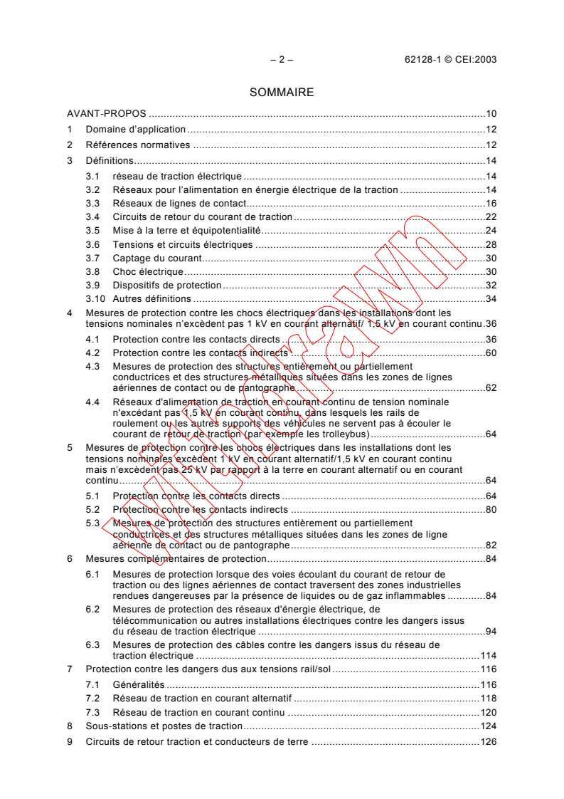
– 2 – 62128-1 © CEI:2003
SOMMAIRE
AVANT-PROPOS .10
1 Domaine d’application .12
2 Références normatives .12
3 Définitions.14
3.1 réseau de traction électrique .14
3.2 Réseaux pour l’alimentation en énergie électrique de la traction .14
3.3 Réseaux de lignes de contact.16
3.4 Circuits de retour du courant de traction.22
3.5 Mise à la terre et équipotentialité.24
3.6 Tensions et circuits électriques .28
3.7 Captage du courant.30
3.8 Choc électrique.30
3.9 Dispositifs de protection.32
3.10 Autres définitions .34
4 Mesures de protection contre les chocs électriques dans les installations dont les
tensions nominales n’excèdent pas 1 kV en courant alternatif/ 1,5 kV en courant continu.36
4.1 Protection contre les contacts directs .36
4.2 Protection contre les contacts indirects .60
4.3 Mesures de protection des structures entièrement ou partiellement
conductrices et des structures métalliques situées dans les zones de lignes
aériennes de contact ou de pantographe .62
4.4 Réseaux d'alimentation de traction en courant continu de tension nominale
n'excédant pas 1,5 kV en courant continu, dans lesquels les rails de
roulement ou les autres supports des véhicules ne servent pas à écouler le
courant de retour de traction (par exemple les trolleybus).64
5 Mesures de protection contre les chocs électriques dans les installations dont les
tensions nominales excèdent 1 kV en courant alternatif/1,5 kV en courant continu
mais n’excèdent pas 25 kV par rapport à la terre en courant alternatif ou en courant
continu.64
5.1 Protection contre les contacts directs .64
5.2 Protection contre les contacts indirects .80
5.3 Mesures de protection des structures entièrement ou partiellement
conductrices et des structures métalliques situées dans les zones de ligne
aérienne de contact ou de pantographe.82
6 Mesures complémentaires de protection.84
6.1 Mesures de protection lorsque des voies écoulant du courant de retour de
traction ou des lignes aériennes de contact traversent des zones industrielles
rendues dangereuses par la présence de liquides ou de gaz inflammables .84
6.2 Mesures de protection des réseaux d'énergie électrique, de
télécommunication ou autres installations électriques contre les dangers issus
du réseau de traction électrique .94
6.3 Mesures de protection des câbles contre les dangers issus du réseau de
traction électrique .114
7 Protection contre les dangers dus aux tensions rail/sol .116
7.1 Généralités .116
7.2 Réseau de traction en courant alternatif .118
7.3 Réseau de traction en courant continu .120
8 Sous-stations et postes de traction.124
9 Circuits de retour traction et conducteurs de terre .126
62128-1 IEC:2003 – 3 –
CONTENTS
FOREWORD .11
1 Scope .13
2 Normative references.13
3 Definitions.15
3.1 electric traction system .15
3.2 Traction power supply systems.15
3.3 Contact line systems .17
3.4 Return current circuits.23
3.5 Earthing and bonding .25
3.6 Voltages and electrical circuits .29
3.7 Current collection.31
3.8 Electric shock .31
3.9 Protective devices.33
3.10 Other definitions .35
4 Protective provisions against electric shock in installations for nominal voltages up
to and including 1 kV a.c./1,5 kV d.c.37
4.1 Protection against direct contact .37
4.2 Protection against indirect contact.61
4.3 Protective provisions for wholly or partially conductive structures and for
metallic structures located in the overhead contact line zone or the
pantograph zone .63
4.4 Traction power supply systems with nominal voltages up to and including
1,5 kV d.c. in which the running rails or other support systems are not utilized
for carrying traction return current (for example trolleybus) .65
5 Protective provisions against electric shock in installations for nominal voltages in
excess of 1 kV a.c./1,5 kV d.c. up to 25 kV a.c. or d.c. to earth.65
5.1 Protection against direct contact .65
5.2 Protection against indirect contact.81
5.3 Protective provisions for wholly or partially conductive structures and for
metallic structures located in the overhead contact line zone or the
pantograph zone .83
6 Additional protective provisions .85
6.1 Protective provisions where track systems, which are utilized for carrying
traction return current, or overhead contact line systems pass through plant
areas in which flammable liquids or gases are utilized in hazardous zones .85
6.2 Protective provisions for electric power, telecommunications and other
electrical installations against the danger of the traction power supply system .95
6.3 Protective provisions for cables against the danger of the traction power
supply system .115
7 Protection against the danger of rail potential .117
7.1 General .117
7.2 AC traction systems .119
7.3 DC traction systems.121
8 Substations and switching stations .125
9 Return current circuits and earthing conductors .127
– 4 – 62128-1 © CEI:2003
10 Moyens pour obtenir une isolation sûre.128
11 Dépose des lignes aériennes de contact hors service .128
Annexe A (informative) Obstacles typiques .130
Annexe B (normative) Signal d’avertissement .134
Annexe C (informative) Valeurs guides pour la détermination des tensions rail/sol .136
Annexe D (informative) Tension de contact/accessible et courant traversant le corps .144
Annexe E (normative) Méthodes de mesure des tensions de contact/accessibles.156
Bibliographie .158
Figure 1 – Zone de ligne aérienne de contact et zone de pantographe.20
Figure 2 – Distances d’éloignement des parties sous tension des lignes aériennes de
contact ou des parties sous tension accessibles à l’extérieur des véhicules à partir des
aires de passage accessibles aux personnes de tensions nominales n’excédant pas
1 kV en courant alternatif/1,5 kV en courant continu.38
Figure 3 – Aires de passage permettant l’accès des personnes à des parties sous
tension extérieures aux véhicules et à des lignes aériennes de contact .40
Figure 4 – Aires de passage permettant l’accès des personnes à des parties sous
tension extérieures aux véhicules et à des rails de contact.42
Figure 5 – Exemples d’obstacles pour aires de passage en zones non accessibles au public
pour la protection contre les contacts directs avec parties sous tension adjacentes à
l’extérieur des véhicules ou celles des lignes de contact pour tensions nominales n’excédant
pas 1 kV en courant alternatif/1,5 kV en courant continu (voir 4.1.3.2.2).44
Figure 6 – Exemples d’obstacles pour aires de passage en zones non accessibles au
public pour la protection contre les contacts directs au-dessus des parties sous tension
à l’extérieur des véhicules ou celles des lignes de contact pour tensions nominales
n’excédant pas 1 kV en courant alternatif/1,5 kV en courant continu (voir 4.1.3.2.3) .48
Figure 7 – Exemple d’un obstacle isolé placé sous une structure (voir 4.1.3.2.4) .50
Figure 8 – Structures en bord de voie .52
Figure 9 – Mât de signaux et/ou de téléphone .52
Figure 10 – Chemin latéral autorisé .52
Figure 11 – Passage à niveau d’accès contrôlé (dépôts, cours de marchandises,
traversées de gare) .54
Figure 12 – Exemples d’obstacles pour aires de passage en zones accessibles au public
pour la protection contre les contacts directs avec parties sous tension adjacentes à
l’extérieur des véhicules ou celles des lignes de contact pour tensions nominales n’excédant
pas 1 kV en courant alternatif/1,5 kV en courant continu (voir 4.1.3.3.1).56
Figure 13 – Passages à niveau publics et privés .58
Figure 14 – Distances d’éloignement des parties sous tension accessibles des lignes
aériennes de contact ou des parties sous tension à l’extérieur des véhicules à partir des
aires de passage accessibles aux personnes de tensions nominales excédant 1 kV en
courant alternatif/1,5 kV en courant continu jusqu’à 25 kV en courant alternatif ou
continu par rapport à la terre .66
Figure 15 – Aires de passage permettant l’accès des personnes à des parties sous
tension extérieures aux véhicules et à des lignes aériennes de contact dépassant 1 kV
en courant alternatif/1,5 kV en courant continu jusqu’à 25 kV en courant alternatif ou
continu par rapport à la terre .70
62128-1 IEC:2003 – 5 –
10 Means of achieving safe isolation .129
11 Removing of decommissioned overhead contact lines .129
Annex A (informative) Typical obstacles.131
Annex B (normative) Warning sign.135
Annex C (informative) Guide values for specific rail potential .137
Annex D (informative) Touch/accessible voltage and body current .145
Annex E (normative) Measurement methods for touch/accessible voltages .157
Bibliography .159
Figure 1 – Overhead contact line zone and pantograph zone. 1
Figure 2 – Clearances to accessible live parts on the outside of vehicles as well as to
live parts of overhead contact line systems from standing surfaces accessible to
persons for nominal voltages up to and including 1 kV a.c./1,5 kV d.c. .39
Figure 3 – Standing surfaces for persons providing access to live parts on the outside of
vehicles and to overhead contact line systems .41
Figure 4 – Standing surfaces for persons providing access to live parts on the outside of
vehicles and to conductor rail systems.43
Figure 5 – Examples of obstacles for standing surfaces in restricted areas for protection
against direct contact with adjacent live parts on the outside of vehicles or adjacent live
parts of a contact line system for nominal voltages up to and including
1 kV a.c./1,5 kV d.c. (see 4.1.3.2.2) .45
Figure 6 – Examples of obstacles for standing surfaces in restricted areas for protection
against direct contact when above live parts on the outside of vehicles or live parts of a
contact line system for nominal voltages up to and including 1 kV a.c./1,5 kV d.c. (see
4.1.3.2.3) .49
Figure 7 – Example of an insulated obstacle beneath a structure (see 4.1.3.2.4) .51
Figure 8 – Trackside structures .53
Figure 9 – Signal post telephone.53
Figure 10 – Authorized trackside walking route .53
Figure 11 – Railway controlled Crossing (Depots, Goods Yard, Station Crossing).55
Figure 12 – Examples of obstacles for standing surfaces in public areas for protection
against direct contact with adjacent live parts on the outside of vehicles or adjacent live
parts of a contact line system for nominal voltages up to and including 1 kV a.c./1,5 kV
d.c. (see 4.1.3.3.1) .57
Figure 13 – Public Level Crossing, Private Level Crossing .59
Figure 14 – Clearances to accessible live parts on the outside of vehicles as well as to
live parts of overhead contact line systems from standing surfaces accessible to
persons for nominal voltages in excess of 1 kV a.c. /1,5 kV d.c. up to 25 kV a.c. or d.c.
to earth .67
Figure 15 – Standing surfaces for persons providing access to live parts on the outside
of vehicles and to overhead contact line systems in excess of 1 kV a.c. /1,5 kV d.c. up
to 25 kV a.c. or d.c. to earth .71
– 6 – 62128-1 © CEI:2003
Figure 16 – Exemples d’obstacles pour aires de passage en zones non accessibles au
public pour la protection contre les contacts directs avec parties sous tension
adjacentes à l’extérieur des véhicules ou celles des lignes aériennes de contact pour
tensions nominales dépassant 1 kV en courant alternatif/1,5 kV en courant continu
jusqu’à 25 kV en courant alternatif ou continu par rapport à la terre (voir 5.1.3.2.1) .74
Figure 17 – Exemples d’obstacles pour aires de passage en zones non accessibles au
public pour la protection contre les contacts directs au-dessus de parties sous tension à
l’extérieur des véhicules ou celles des lignes aériennes de contact pour tensions
nominales dépassant 1 kV en courant alternatif/1,5 kV en courant continu jusqu’à 25 kV
en courant alternatif ou continu par rapport à la terre (voir 5.1.3.2.2).76
Figure 18 – Exemples d’obstacles pour aires de passage en zones accessibles au
public pour la protection contre les contacts directs avec parties sous tension
adjacentes à l’extérieur des véhicules ou celles des lignes aériennes de contact pour
tensions nominales dépassant 1 kV en courant alternatif/1,5 kV en courant continu
jusqu’à 25 kV en courant alternatif ou continu par rapport à la terre (voir 5.1.3.3.1) .78
Figure 19 – Disposition des joints isolants de rails (exemple d’une double voie) dans le
cas d'une voie de débord dépourvue de ligne aérienne de contact et située hors de la
zone de ligne aérienne de contact de la voie voisine (voir 6.1.5).86
Figure 20 – Disposition des joints isolants des rails (exemple d’une double voie), de la
mise à la terre indirecte par le réseau de traction (limiteur de tension), et du schéma
d’alimentation de la ligne aérienne de contact dans le cas d'une voie de débord située
dans la zone de ligne aérienne de contact de la voie voisine (voir 6.1.6) .88
Figure 21 – Disposition des liaisons transversales de rail à rail et de voie à voie
(exemple d’une double voie) et du schéma d’alimentation de la ligne aérienne de
contact dans le cas d'une voie de débord avec ligne aérienne de contact (voir 6.1.3 et
6.1.7) .90
Figure 22 – Emplacement du parafoudre dans le cas où les pièces isolantes se trouvent
entre les équipements terminaux de chargement et l’installation de chargement, en
dehors de la zone de ligne aérienne de contact d'une voie de débord, si la foudre est
susceptible de provoquer le contournement de ces pièces isolantes (voir 6.1.8.2 et
6.1.8.3) .92
Figure 23 – Emplacement du limiteur de tension si les pièces isolantes se trouvent entre
les équipements terminaux de chargement et l’installation de chargement, dans la zone
de ligne aérienne de contact d'une voie de débord (voir 6.1.8.2) .92
Figure 24 – Exemple de mesures de protection des masses pour les réseaux de traction
en courant alternatif alimentés par un réseau TT dans lequel le conducteur de
protection est relié à la terre du réseau de traction (voir 6.2.4.2.1) .96
Figure 25 – Exemple de mesures de protection des masses pour les réseaux de traction
en courant alternatif alimentés par un réseau TN dans lequel le conducteur PEN et le
conducteur de protection sont reliés à la terre du réseau de traction (voir 6.2.4.2.2) .98
Figure 26 – Exemple de mesures de protection des masses des réseaux de traction en
courant alternatif alimentés par un réseau IT dans lequel le conducteur de protection PE
n’est pas relié au neutre d’un transformateur en étoile (voir 6.2.4.2.3).100
Figure 27 – Exemple de mesures de protection des masses des réseaux de traction en
courant alternatif alimentés par un réseau TT ou TN dans le cas d’utilisation de
disjoncteurs à courant différentiel résiduel (voir 6.2.4.2.4.1).102
Figure 28 – Exemple de mesures de protection des masses des réseaux de traction en
courant alternatif lorsque l’alimentation du réseau d’électricité ferroviaire est assurée
par un poste à haute tension qui lui est propre ou un transformateur à enroulements
séparés (voir 6.2.4.2.4.2).104
Figure 29 – Exemple de mesures de protection des masses des réseaux de traction en
courant continu situées hors de la zone de ligne aérienne de contact ou de la zone de
pantographe, lorsque les rails de roulement sont isolés par rapport à la terre (voir
6.2.4.3.1.1).106
62128-1 IEC:2003 – 7 –
Figure 16 – Examples of obstacles for standing surfaces in restricted areas for
protection against direct contact with adjacent live parts on the outside of vehicles or
adjacent live parts of an overhead contact line system for nominal voltages in excess of
1 kV a.c./1,5 kV d.c. up to 25 kV a.c. or d.c. to earth (see 5.1.3.2.1) .75
Figure 17 – Examples of obstacles for standing surfaces in restricted areas for
protection against direct contact when above live parts on the outside of vehicles or live
parts of an overhead contact line system for nominal voltages in excess of
1 kV a.c./1,5 kV d.c. up to 25 kV a.c. or d.c. to earth (see 5.1.3.2.2) .77
Figure 18 – Examples of obstacles for standing surfaces in public areas for protection
against direct contact with adjacent live parts on the outside of vehicles or adjacent live
parts of an overhead contact line system for nominal voltages in excess of 1 kV a.c./
1,5 kV d.c. up to 25 kV a.c. or d.c. to earth (see 5.1.3.3.1) .79
Figure 19 – Disposition of insulated rail joints (double-track illustration) in the case of
the loading siding having no overhead contact line and lying outside the overhead
contact line zone of the neighbouring track (see 6.1.5).87
Figure 20 – Disposition of insulated rail joints (double-track illustration), open traction
system earthing (voltage-limiting device) and connection of the overhead contact line in
the case of the loading siding being within the overhead contact line zone of the
neighbouring track (see 6.1.6) .89
Figure 21 – Disposition of rail-to-rail crossbonds and track-to-track crossbonds (double-
track illustration) and connection of the overhead contact line in case of the loading
siding having an overhead contact line (see 6.1.3 and 6.1.7).91
Figure 22 – Location of a surge arrester if isolation pieces are between charging nozzle
and refilling pipe outside the overhead contact line zone of a loading siding with over-
head contact line and if there is a possibility of flashovers of the isolation pieces through
lightning strikes (see 6.1.8.2 and 6.1.8.3).93
Figure 23 – Location of a voltage-limiting device if isolation pieces are between charging
nozzle and refilling pipe inside the overhead contact line zone of a loading siding with
overhead contact line (see 6.1.8.2) .93
Figure 24 – Example for protective provisions of exposed conductive parts for a.c.
traction systems supplied from TT system in which the protective conductor is
connected with the traction system earth (see 6.2.4.2.1) .97
Figure 25 – Example for protective provisions of exposed conductive parts for a.c.
traction systems supplied from TN system in which the PEN conductor and the
protective conductor are connected with the traction system earth (see 6.2.4.2.2) .99
Figure 26 – Example for protective provisions of exposed conductive parts for a.c.
traction systems supplied from an IT system, in which the PE is not connected with the
starpoint of the transformer (see 6.2.4.2.3) .101
Figure 27 – Example for protective provisions of exposed conductive parts for a.c.
traction systems supplied from TT system or TN system with utilization of residual
current- operated protective devices (see 6.2.4.2.4.1).103
Figure 28 – Example for protective provisions of exposed conductive parts for a.c.
traction systems by electrical isolation from the power supply system by means of a
separate high voltage station or a transformer with separate windings (see 6.2.4.2.4.2) .105
Figure 29 – Example for protective provisions of exposed conductive parts for d.c.
traction systems outside the overhead contact line zone or the pantograph zone if the
running rails are insulated from earth (see 6.2.4.3.1.1).107
– 8 – 62128-1 © CEI:2003
Figure 30 – Exemple de mesures de protection des masses des réseaux de traction en
courant continu situées hors de la zone de ligne aérienne de contact ou de la zone de
pantographe, lorsque les rails de roulement sont reliés directement à la terre ou à des
fonds de fouille de bâtiment (voir 6.2.4.3.1.2).108
Figure 31 – Exemple de mesures de protection des masses de réseaux de traction en
courant continu alimentés par un réseau TN dans la zone de ligne aérienne de contact
ou dans la zone de pantographe, lorsque les rails de roulement sont isolés par rapport
à la terre (voir 6.2.4.3.2.1) .110
Figure 32 – Exemple de mesures de protection des masses de réseaux de traction en
courant continu situées dans la zone de ligne aérienne de contact ou dans la zone de
pantographe, lorsque les rails de roulement sont directement reliés à la terre ou au fond
de fouille du bâtiment (voir 6.2.4.3.2.2) .112
Figure 33 – Exemple de mesures de protection des masses des réseaux de traction en
courant continu alimentés par un réseau IT dans lequel le conducteur de protection PE
n’est pas relié au neutre d’un transformateur en étoile (voir 6.2.4.3.2.3) .114
Figure A.1 – Exemples d’obstacles latéraux pour les aires de passage en zones
accessibles au public pour la protection contre les contacts directs au-dessus des
parties sous tension appartenant à des véhicules ou des lignes de contact pour des
tensions nominales n’excédant pas 1 kV en courant alternatif ou 1,5 kV en courant
continu (voir 4.1.3.3.2).130
Figure A.2 – Exemples d’obstacles latéraux pour les aires de passage en zones
accessibles au public pour la protection contre les contacts directs au-dessus des
parties sous tension appartenant à des véhicules ou des lignes aériennes de contact
pour des tensions nominales excédant 1 kV en courant alternatif ou 1,5 kV en courant
continu mais n’excédant pas 25 kV en courant alternatif ou continu (voir 5.1.3.3.2) .132
Figure C.1 – Valeurs guides des tensions rail/sol U' dans un réseau de traction en
courant alternatif .136
Figure C.2 – Valeurs guides de la décroissance de la tension pour des sections à
double voie et une valeur moyenne de la résistance de terre mesurée
perpendiculairement à la voie dans un réseau de traction en courant alternatif.138
Figure C.3 – Valeurs guides des tensions dans un réseau en courant continu à double
voie pour différentes distances (l) à partir du point d’injection.142
Figure C.4 – Valeurs guides des tensions dans un réseau en courant continu à voie
unique pour différentes distances (l) à partir du point d’injection.142
Figure D.1 .150
Figure D.2 .154
Tableau 1 – Conditions de durée .116
Tableau 2 – Tensions de contact maximales admises U dans les réseaux de traction
t
en courant alternatif en fonction des conditions de courte durée.118
Tableau 3 – Tensions accessibles maximales admises U dans les réseaux de traction
a
en courant alternatif en fonction des conditions temporaires .118
Tableau 4 – Tensions de contact maximales admises U dans les réseaux de traction
t
en courant continu en fonction des conditions de courte durée.122
Tableau 5 – Tensions accessibles maximales admises U dans les réseaux de traction
a
en courant continu en fonction des conditions temporaires.122
Tableau D.1 – Impédance du corps Z et courant à travers le corps I .146
B
Tableau D.2 – Courants à travers le corps et tension de contact/accessible en fonction
de la durée dans les réseaux de traction en courant alternatif .148
Tableau D.3 – Courant à travers le corps et tensions de contact ou accessible en
fonction de la durée.152
62128-1 IEC:2003 – 9 –
Figure 30 – Example for protective provisions of exposed conductive parts for d.c.
traction systems outside the overhead contact line zone or the pantograph zone if the
running rails are directly connected to earth or to foundations of buildings
(see 6.2.4.3.1.2) .109
Figure 31 – Example for protective provisions of exposed conductive parts for
d.c. traction systems supplied from TN system within the overhead contact line zone or
the pantograph zone if the running rails are insulated from earth (see 6.2.4.3.2.1).111
Figure 32 – Example for protective provisions of exposed conductive parts for d.c.
traction systems within the overhead contact line zone or the pantograph zone if the
running rails are directly connected to earth or to foundations of buildings (see
6.2.4.3.2.2).113
Figure 33 – Example for protective provisions of exposed conductive parts for
d.c. traction systems supplied from an IT system, in which the PE is not connected with
the starpoint of the transformer (see 6.2.4.3.2.3) .115
Figure A.1 – Examples of obstacles along the sides of standing surfaces in public areas
for protection against direct contact when above live parts on the outside of vehicles or
live parts of an overhead contact line system for nominal voltages up to and including
1 kV a.c/1,5 kV d.c. (see 4.1.3.3.2) .131
Figure A.2 – Examples of obstacles along the sides of standing surfaces in public areas
for protection against direct contact when above live parts on the outside of vehicles or
live parts of an overhead contact line system for nominal voltages in excess of
1 kV a.c./1,5 kV d.c. up to 25 kV a.c. or d.c. (see 5.1.3.3.2) .133
Figure C.1 – Guide values for the specific rail potential U' in an a.c. traction system .137
Figure C.2 – Guide values for the potential decrease for double-track sections and
average soil resistivity measured at right angle away from the track in an a.c. traction
system .139
Figure C.3 – Guide values for specific rail potential in d.c. double track system for
different distances (l) from the injection point.143
Figure C.4 – Guide values for specific rail potential in d.c. single track system for
different distances (l) from the injection point.143
Figure D.1 .151
Figure D.2 .155
Table 1 – Time duration conditions .117
Table 2 – Maximum permissible touch voltages U in a.c. traction systems as a function
t
of short time conditions .119
Table 3 – Maximum permissible accessible voltages U in a.c. traction systems as a
a
function of temporary conditions .119
Table 4 – Maximum permissible touch voltages U in d.c. traction systems as a function
t
of short time conditions. .123
Table 5 – Maximum permissible accessible voltages U in d.c. traction systems as a
a
function of temporary conditions .123
Table D.1 – Body impedance Z and body current I .147
B
Table D.2 – Body currents and touch/accessible voltages as a function of the time
duration in a.c. traction systems .149
Table D.3 – Body currents and touch/accessible voltages as function of time duration in
d.c. traction system .153
– 10 – 62128-1 © CEI:2003
COMMISSION ÉLECTROTECHNIQUE INTERNATIONALE
___________
APPLICATIONS FERROVIAIRES – INSTALLATIONS FIXES –
Partie 1: Mesures de protection relatives à la sécurité électrique
et à la mise à la terre
AVANT-PROPOS
1) La CEI (Commission Électrotechnique Internationale) est une organisation mondiale de normalisation composée
de l'ensemble des comités électrotechniques nationaux (Comités nationaux de la CEI). La CEI a pour objet de
favoriser la coopération internationale pour toutes les
...
Questions, Comments and Discussion
Ask us and Technical Secretary will try to provide an answer. You can facilitate discussion about the standard in here.
Loading comments...