

IEC 61308:2026
(Main)High-frequency dielectric heating installations - Test methods for the determination of power output
- Abstract
IEC 61308:2026 specifies test methods for the determination of useful high frequency power output in equipment for industrial heating and processing of materials. It is in particular applicable to HF generators made available to users as separate units. This document is basically applicable to equipment operating in the frequency range 100 kHz to 300 MHz, as defined in IEC 60519-1, with the following limitations. This document does not apply to induction heating, which it is possible to carry out in the lower part of the specified frequency band. The ISM centre frequencies for dielectric heating and processing of industrial interest are narrow bands about 6,78 MHz, 13,56 MHz, 27,12 MHz and 40,68 MHz.
This document is not applicable to:
- appliances for household and similar use;
- commercial use;
- laboratory use;
- medical high frequency equipment.
For equipment working in designated ISM bands, it is a legal requirement that the frequency remains within the ISM bands according to CISPR 11, but the resonant frequency of the circuit varies with the change of dielectric parameters of the load. Therefore, the value of the mean output power in the work cycle can be much lower than the value obtained under the test conditions. This value depends upon the response of the tuning system.
NOTE 1 The following criteria are suitable for determination of the classification as industrial equipment:
– commercial equipment is typically designed and planned for series production of many identical units;
– industrial equipment is typically produced in small series or even as single units; the processed goods are consumed or ready for final use at the end of the heating process.
NOTE 2 Heating a workload with dielectric parameters which change significantly in time and/or with temperature, the value of the output power obtained with the actual charge can be different from that obtained with the test load specified in this document.
This document relates to equipment normally operating under continuous rated conditions.
This third edition cancels and replaces the second edition published in 2005. This edition constitutes a technical revision. This edition includes the following significant technical changes with respect to the previous edition:
a) adaptation and alignment to the principles in more recent editions of IEC 60519-1 and IEC 60519-6;
b) more detailed descriptions of, in particular, the calorimetric load test and output power evaluation for dielectic plastic welders.
- Status
- Published
- Publication Date
- 05-Aug-2026
- Technical Committee
- TC 27 - Industrial electroheating and electromagnetic processing
- Drafting Committee
- MT 23 - TC 27/MT 23
- Current Stage
- PPUB - Publication issued
- Start Date
- 06-Aug-2026
- Completion Date
- 04-Sep-2026
Buy Documents
IEC 61308:2026 - High-frequency dielectric heating installations - Test methods for the determination of power output
REDLINE IEC 61308:2026 RLV - High-frequency dielectric heating installations - Test methods for the determination of power output
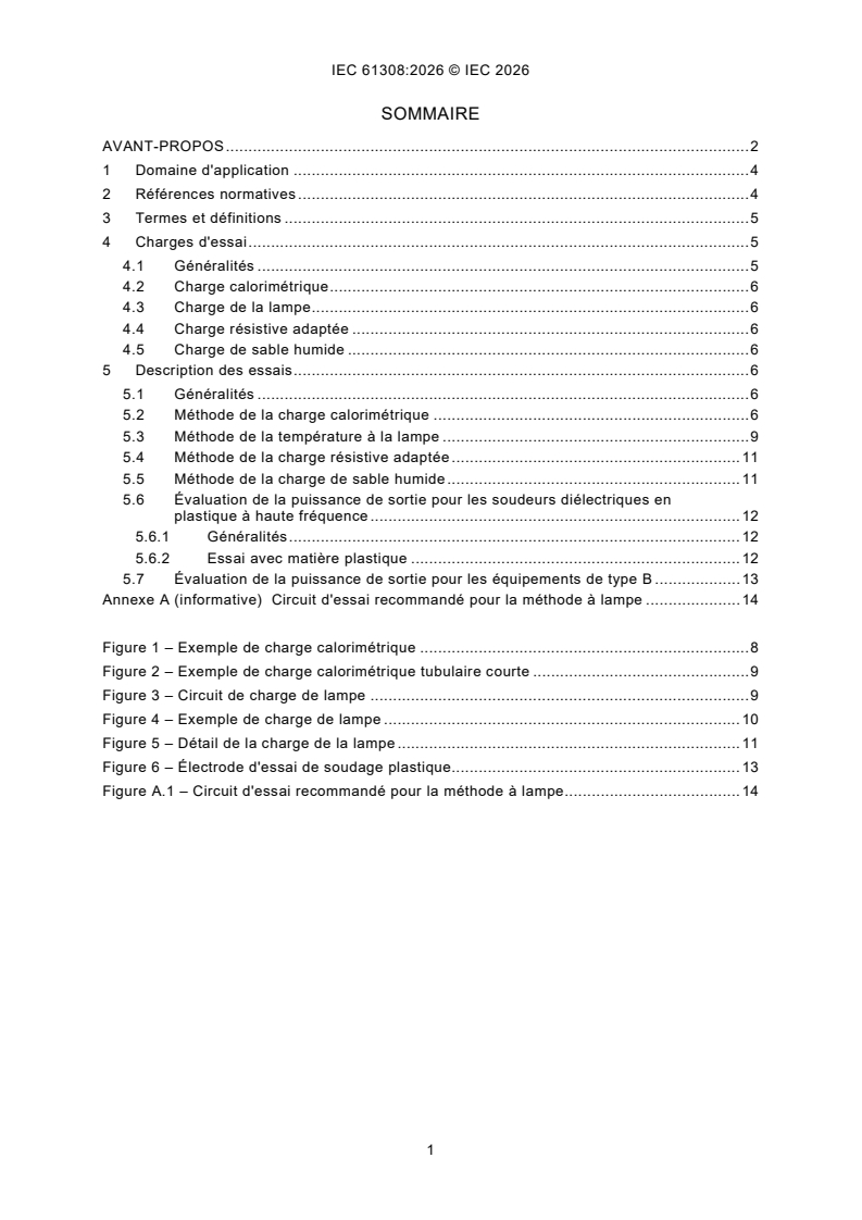
IEC 61308:2026 - Installations de chauffage diélectrique a haute fréquence - Méthodes d'essai pour la détermination de la puissance de sortie
IEC 61308:2026 is an IEC International Standard for test methods used to determine useful high-frequency power output in industrial heating and processing equipment. It is aimed mainly at high-frequency (HF) generators supplied as separate units, and it also covers output evaluation for high-frequency dielectric plastic welders and type B equipment. In practice, it tells manufacturers and test engineers which load, circuit, and measurement method to use so output-power results are comparable.
What does IEC 61308:2026 specify?
IEC 61308:2026 specifies how to determine useful high-frequency power output for equipment used in industrial heating and processing of materials. It applies mainly to equipment operating from 100 kHz to 300 MHz, with limits for induction heating and for non-industrial uses.
| Annex | What it covers |
|---|---|
| Annex A | Recommended test circuit for the lamp-load method |
The document is organized into scope, normative references, terms and definitions, test loads, and descriptions of the test methods. Clause 4 sets out the load types, and Clause 5 gives the measurement methods for each case.
What are the key requirements of IEC 61308:2026?
Clause 4 - choose a load that represents the real application
IEC 61308:2026 requires the test load to represent the normal load as closely as practical in dimensions and impedance. That matters because the measured output power depends on how well the generator is matched to the load.
Clause 4 identifies four test loads: calorimetric load, lamp load, matched resistive load, and wet-sand load. For plastic welders, the document also uses a dedicated plastic welding test electrode.
Clause 5.2 - calorimetric load method
IEC 61308:2026 uses a water-based calorimetric load for higher power levels, especially around 1 kW and above. The generator is run with the normal load, then replaced by the calorimetric load without significant retuning, and the water flow and temperature rise are used to calculate output power.
The method requires controlled water conditions and good mixing to avoid hot spots and steam. In practice, this means the operator must watch flow, inlet and outlet temperature, and thermal equilibrium before taking the reading.
Clause 5.3 - lamp-load temperature method
IEC 61308:2026 allows incandescent lamps as a load when the output terminals are accessible and the power level is up to about 1 kW. The lamp temperature under high-frequency supply is matched against a comparison lamp on mains frequency supply, and the electrical power of the comparison lamp gives the output power.
This method is not recommended above 30 MHz and is practically not applicable above 100 MHz. It is therefore most useful for lower-frequency HF equipment where the terminals can be connected directly.
Clause 5.4 and 5.5 - resistive load and wet-sand load
IEC 61308:2026 permits a matched resistive load when the generator can be connected directly to a low-reactance resistor. This is a straightforward method when a suitable commercial load is available and the connection arrangement is simple.
The wet-sand load method is intended for some type B equipment. It uses wet sand in the applicator and determines power from the water loss during heating, so it is more of a practical field method than a precision laboratory method.
Clause 5.6 and 5.7 - plastic welders and type B equipment
IEC 61308:2026 gives a specific approach for high-frequency dielectric plastic welders. When the generator terminals are accessible, the useful output power is measured with one of the standard load methods; when they are not accessible, the plastic welding test electrode is used to evaluate the installation.
For type B equipment, direct output measurement is not possible, so the document uses calculation from the tube or circuit data and an estimated circuit efficiency. That matters for built-in generators where the output cannot be separated from the applicator.
What terms does IEC 61308:2026 define?
- Type A equipment - HF equipment where the generator is separate from, or separable from, the applicator.
- Type B equipment - HF equipment where the generator is directly coupled to the applicator.
- Useful output power - for type A equipment, the maximum power measured in a test load; for type B equipment, the HF power developed in the normal load.
- Calorimetric load - a substitute load that uses water heating to measure output power.
- Lamp load - a load made from incandescent lamps, used for lower-power measurements.
- Matched resistive load - a low-reactance resistor used as a direct HF load.
- Plastic welding test electrode - the defined cutting-edge electrode used to evaluate plastic welding output.
Who uses IEC 61308:2026?
IEC 61308:2026 is used by manufacturers of industrial HF generators, suppliers of dielectric heating systems, and makers of high-frequency dielectric plastic welders. It also serves test engineers, quality managers, and buyers who need a repeatable way to verify rated output power.
The document is especially relevant when the generator is supplied as a separate unit, when the output terminals are accessible, or when a built-in type B arrangement needs calculated or indirect output evaluation.
What changed in IEC 61308:2026 from the previous edition?
IEC 61308:2026 cancels and replaces the second edition published in 2005. This edition is a technical revision.
The changes stated in the document are:
- alignment with more recent editions of IEC 60519-1 and IEC 60519-6;
- more detailed description of the calorimetric load test;
- more detailed output-power evaluation for dielectric plastic welders.
Which standards are used with IEC 61308:2026?
- IEC 60050-841 - provides the International Electrotechnical Vocabulary terms for industrial electroheat.
- IEC 60519-1 - gives the general safety requirements and the frequency range basis used in the scope.
- IEC 60519-6 - gives the particular safety requirements for high frequency dielectric and microwave heating and processing equipment.
- CISPR 11 - is referenced in the scope for keeping operation within designated ISM bands.
What does the IEC 61308:2026 document contain?
IEC 61308:2026 contains four test-load descriptions, five main test-method sections, one informative annex, and six figures. The figures show example calorimeter loads, the lamp-load circuit and load arrangement, and the plastic welding test electrode.
It also includes two calculation formulas: one for calorimetric water heating and one for the wet-sand load method. Those formulas support practical power measurement during testing, commissioning, and output verification.
Annex A gives a recommended test circuit for the lamp-load method using a silicon photoelectric cell and calibration curve. That annex is useful when the lamp-load method is chosen and the operator needs a traceable way to relate lamp brightness to power.
Relations
- Effective Date
- 31-Jan-2025
Buy Documents
IEC 61308:2026 - High-frequency dielectric heating installations - Test methods for the determination of power output
REDLINE IEC 61308:2026 RLV - High-frequency dielectric heating installations - Test methods for the determination of power output
IEC 61308:2026 - Installations de chauffage diélectrique a haute fréquence - Méthodes d'essai pour la détermination de la puissance de sortie
Get Certified
Connect with accredited certification bodies for this standard

DVS-ZERT GmbH
German welding certification society.
CARES (UK Certification Authority for Reinforcing Steels)
UK certification for reinforcing steels and construction.
EWF/IIW (European/International Welding Federation)
International welding personnel certification.
Sponsored listings
Frequently Asked Questions
IEC 61308:2026 is a standard published by the International Electrotechnical Commission (IEC). Its full title is "High-frequency dielectric heating installations - Test methods for the determination of power output". This standard covers: IEC 61308:2026 specifies test methods for the determination of useful high frequency power output in equipment for industrial heating and processing of materials. It is in particular applicable to HF generators made available to users as separate units. This document is basically applicable to equipment operating in the frequency range 100 kHz to 300 MHz, as defined in IEC 60519-1, with the following limitations. This document does not apply to induction heating, which it is possible to carry out in the lower part of the specified frequency band. The ISM centre frequencies for dielectric heating and processing of industrial interest are narrow bands about 6,78 MHz, 13,56 MHz, 27,12 MHz and 40,68 MHz. This document is not applicable to: - appliances for household and similar use; - commercial use; - laboratory use; - medical high frequency equipment. For equipment working in designated ISM bands, it is a legal requirement that the frequency remains within the ISM bands according to CISPR 11, but the resonant frequency of the circuit varies with the change of dielectric parameters of the load. Therefore, the value of the mean output power in the work cycle can be much lower than the value obtained under the test conditions. This value depends upon the response of the tuning system. NOTE 1 The following criteria are suitable for determination of the classification as industrial equipment: – commercial equipment is typically designed and planned for series production of many identical units; – industrial equipment is typically produced in small series or even as single units; the processed goods are consumed or ready for final use at the end of the heating process. NOTE 2 Heating a workload with dielectric parameters which change significantly in time and/or with temperature, the value of the output power obtained with the actual charge can be different from that obtained with the test load specified in this document. This document relates to equipment normally operating under continuous rated conditions. This third edition cancels and replaces the second edition published in 2005. This edition constitutes a technical revision. This edition includes the following significant technical changes with respect to the previous edition: a) adaptation and alignment to the principles in more recent editions of IEC 60519-1 and IEC 60519-6; b) more detailed descriptions of, in particular, the calorimetric load test and output power evaluation for dielectic plastic welders.
IEC 61308:2026 specifies test methods for the determination of useful high frequency power output in equipment for industrial heating and processing of materials. It is in particular applicable to HF generators made available to users as separate units. This document is basically applicable to equipment operating in the frequency range 100 kHz to 300 MHz, as defined in IEC 60519-1, with the following limitations. This document does not apply to induction heating, which it is possible to carry out in the lower part of the specified frequency band. The ISM centre frequencies for dielectric heating and processing of industrial interest are narrow bands about 6,78 MHz, 13,56 MHz, 27,12 MHz and 40,68 MHz. This document is not applicable to: - appliances for household and similar use; - commercial use; - laboratory use; - medical high frequency equipment. For equipment working in designated ISM bands, it is a legal requirement that the frequency remains within the ISM bands according to CISPR 11, but the resonant frequency of the circuit varies with the change of dielectric parameters of the load. Therefore, the value of the mean output power in the work cycle can be much lower than the value obtained under the test conditions. This value depends upon the response of the tuning system. NOTE 1 The following criteria are suitable for determination of the classification as industrial equipment: – commercial equipment is typically designed and planned for series production of many identical units; – industrial equipment is typically produced in small series or even as single units; the processed goods are consumed or ready for final use at the end of the heating process. NOTE 2 Heating a workload with dielectric parameters which change significantly in time and/or with temperature, the value of the output power obtained with the actual charge can be different from that obtained with the test load specified in this document. This document relates to equipment normally operating under continuous rated conditions. This third edition cancels and replaces the second edition published in 2005. This edition constitutes a technical revision. This edition includes the following significant technical changes with respect to the previous edition: a) adaptation and alignment to the principles in more recent editions of IEC 60519-1 and IEC 60519-6; b) more detailed descriptions of, in particular, the calorimetric load test and output power evaluation for dielectic plastic welders.
IEC 61308:2026 is classified under the following ICS (International Classification for Standards) categories: 25.180.10 - Electric furnaces. The ICS classification helps identify the subject area and facilitates finding related standards.
IEC 61308:2026 has the following relationships with other standards: It is inter standard links to IEC 61308:2005. Understanding these relationships helps ensure you are using the most current and applicable version of the standard.
IEC 61308:2026 is available in PDF format for immediate download after purchase. The document can be added to your cart and obtained through the secure checkout process. Digital delivery ensures instant access to the complete standard document.
Standards Content (Sample)
IEC 61308 ®
Edition 3.0 2026-08
INTERNATIONAL
STANDARD
High-frequency dielectric heating installations - Test methods for the
determination of power output
ICS 25.180.10 ISBN 978-2-8327-1430-0
All rights reserved. Unless otherwise specified, no part of this publication may be reproduced or utilized in any form or
by any means, electronic or mechanical, including photocopying and microfilm, without permission in writing from either
IEC or IEC's member National Committee in the country of the requester. If you have any questions about IEC copyright
or have an enquiry about obtaining additional rights to this publication, please contact the address below or your local
IEC member National Committee for further information.
IEC Secretariat Tel.: +41 22 919 02 11
3, rue de Varembé info@iec.ch
CH-1211 Geneva 20 www.iec.ch
Switzerland
About the IEC
The International Electrotechnical Commission (IEC) is the leading global organization that prepares and publishes
International Standards for all electrical, electronic and related technologies.
About IEC publications
The technical content of IEC publications is kept under constant review by the IEC. Please make sure that you have the
latest edition, a corrigendum or an amendment might have been published.
IEC publications search - IEC Products & Services Portal - products.iec.ch
webstore.iec.ch/advsearchform Discover our powerful search engine and read freely all the
The advanced search enables to find IEC publications by a publications previews, graphical symbols and the glossary.
variety of criteria (reference number, text, technical With a subscription you will always have access to up to date
committee, …). It also gives information on projects, content tailored to your needs.
replaced and withdrawn publications.
Electropedia - www.electropedia.org
The world's leading online dictionary on electrotechnology,
IEC Just Published - webstore.iec.ch/justpublished
Stay up to date on all new IEC publications. Just Published containing more than 22 500 terminological entries in English
details all new publications released. Available online and and French, with equivalent terms in 25 additional languages.
once a month by email. Also known as the International Electrotechnical Vocabulary
(IEV) online.
IEC Customer Service Centre - webstore.iec.ch/csc
If you wish to give us your feedback on this publication or
need further assistance, please contact the Customer
Service Centre: sales@iec.ch.
CONTENTS
FOREWORD . 2
1 Scope . 4
2 Normative references . 4
3 Terms and definitions . 5
4 Test loads . 5
4.1 General . 5
4.2 Calorimetric load . 6
4.3 Lamp load . 6
4.4 Matched resistive load . 6
4.5 Wet-sand load. 6
5 Description of tests . 6
5.1 General . 6
5.2 Calorimetric load method . 6
5.3 Lamp-load temperature method . 9
5.4 Matched resistive load method . 11
5.5 Wet-sand load method . 11
5.6 Evaluation of the output power for high-frequency dielectric plastic welders . 12
5.6.1 General . 12
5.6.2 Test with plastic material . 12
5.7 Evaluation of the output power for type B equipment . 13
Annex A (informative) Recommended test circuit for the lamp-load method . 14
Figure 1 – Example of a calorimeter load . 8
Figure 2 – Example of a short tubular calorimeter load . 9
Figure 3 – Lamp-load circuit . 9
Figure 4 – Example of a lamp load . 10
Figure 5 – Detail of the lamp load . 11
Figure 6 – Plastic welding test electrode . 13
Figure A.1 – Recommended test circuit for the lamp-load method . 14
INTERNATIONAL ELECTROTECHNICAL COMMISSION
____________
High-frequency dielectric heating installations -
Test methods for the determination of power output
FOREWORD
1) The International Electrotechnical Commission (IEC) is a worldwide organization for standardization comprising
all national electrotechnical committees (IEC National Committees). The object of IEC is to promote international
co-operation on all questions concerning standardization in the electrical and electronic fields. To this end and
in addition to other activities, IEC publishes International Standards, Technical Specifications, Technical Reports,
Publicly Available Specifications (PAS) and Guides (hereafter referred to as "IEC Publication(s)"). Their
preparation is entrusted to technical committees; any IEC National Committee interested in the subject dealt with
may participate in this preparatory work. International, governmental and non-governmental organizations liaising
with the IEC also participate in this preparation. IEC collaborates closely with the International Organization for
Standardization (ISO) in accordance with conditions determined by agreement between the two organizations.
2) The formal decisions or agreements of IEC on technical matters express, as nearly as possible, an international
consensus of opinion on the relevant subjects since each technical committee has representation from all
interested IEC National Committees.
3) IEC Publications have the form of recommendations for international use and are accepted by IEC National
Committees in that sense. While all reasonable efforts are made to ensure that the technical content of IEC
Publications is accurate, IEC cannot be held responsible for the way in which they are used or for any
misinterpretation by any end user.
4) In order to promote international uniformity, IEC National Committees undertake to apply IEC Publications
transparently to the maximum extent possible in their national and regional publications. Any divergence between
any IEC Publication and the corresponding national or regional publication shall be clearly indicated in the latter.
5) IEC itself does not provide any attestation of conformity. Independent certification bodies provide conformity
assessment services and, in some areas, access to IEC marks of conformity. IEC is not responsible for any
services carried out by independent certification bodies.
6) All users should ensure that they have the latest edition of this publication.
7) No liability shall attach to IEC or its directors, employees, servants or agents including individual experts and
members of its technical committees and IEC National Committees for any personal injury, property damage or
other damage of any nature whatsoever, whether direct or indirect, or for costs (including legal fees) and
expenses arising out of the publication, use of, or reliance upon, this IEC Publication or any other IEC
Publications.
8) Attention is drawn to the Normative references cited in this publication. Use of the referenced publications is
indispensable for the correct application of this publication.
9) IEC draws attention to the possibility that the implementation of this document may involve the use of (a)
patent(s). IEC takes no position concerning the evidence, validity or applicability of any claimed patent rights in
respect thereof. As of the date of publication of this document, IEC had not received notice of (a) patent(s), which
may be required to implement this document. However, implementers are cautioned that this may not represent
the latest information, which may be obtained from the patent database available at https://patents.iec.ch. IEC
shall not be held responsible for identifying any or all such patent rights.
IEC 61308 has been prepared by IEC technical committee 27: Industrial electroheating and
electromagnetic processing. It is an International Standard.
This third edition cancels and replaces the second edition published in 2005. This edition
constitutes a technical revision.
This edition includes the following significant technical changes with respect to the previous
edition:
a) adaptation and alignment to the principles in more recent editions of IEC 60519-1 and
IEC 60519-6;
b) more detailed descriptions of, in particular, the calorimetric load test and output power
evaluation for dielectic plastic welders.
The text of this International Standard is based on the following documents:
Draft Report on voting
27/1244/FDIS 27/1248/RVD
Full information on the voting for its approval can be found in the report on voting indicated in
the above table.
The language used for the development of this International Standard is English.
This document was drafted in accordance with ISO/IEC Directives, Part 2, and developed in
accordance with ISO/IEC Directives, Part 1 and ISO/IEC Directives, IEC Supplement, available
at www.iec.ch/members_experts/refdocs. The main document types developed by IEC are
described in greater detail at www.iec.ch/publications.
The committee has decided that the contents of this document will remain unchanged until the
stability date indicated on the IEC website under webstore.iec.ch in the data related to the
specific document. At this date, the document will be
– reconfirmed,
– withdrawn, or
– revised.
1 Scope
This document specifies test methods for the determination of useful high frequency power
output in equipment for industrial heating and processing of materials. It is in particular
applicable to HF generators made available to users as separate units.
This document is basically applicable to equipment operating in the frequency range 100 kHz
to 300 MHz, as defined in IEC 60519-1, with the following limitations.
– This document does not apply to induction heating, which it is possible to carry out in the
lower part of the specified frequency band.
– The ISM centre frequencies for dielectric heating and processing of industrial interest are
narrow bands about 6,78 MHz, 13,56 MHz, 27,12 MHz and 40,68 MHz.
– This document is not applicable to:
• appliances for household and similar use;
• commercial use;
• laboratory use;
• medical high frequency equipment.
For equipment working in designated ISM bands, it is a legal requirement that the frequency
remains within the ISM bands according to CISPR 11, but the resonant frequency of the circuit
varies with the change of dielectric parameters of the load. Therefore, the value of the mean
output power in the work cycle can be much lower than the value obtained under the test
conditions. This value depends upon the response of the tuning system.
NOTE 1 The following criteria are suitable for determination of the classification as industrial equipment:
– commercial equipment is typically designed and planned for series production of many identical units;
– industrial equipment is typically produced in small series or even as single units; the processed goods are
consumed or ready for final use at the end of the heating process.
NOTE 2 Heating a workload with dielectric parameters which change significantly in time and/or with temperature,
the value of the output power obtained with the actual charge can be different from that obtained with the test load
specified in this document.
This document relates to equipment normally operating under continuous rated conditions.
2 Normative references
The following documents are referred to in the text in such a way that some or all of their content
constitutes requirements of this document. For dated references, only the edition cited applies.
For undated references, the latest edition of the referenced document (including any
amendments) applies.
IEC 60050-841, International Electrotechnical Vocabulary (IEV) - Part 841: Industrial
electroheat
IEC 60519-1, Safety in installations for electroheating and electromagnetic processing - Part 1:
General requirements
IEC 60519-6, Safety in installations for electroheating and electromagnetic processing - Part 6:
Particular requirements for high frequency dielectric and microwave heating and processing
equipment
3 Terms and definitions
For the purposes of this document, the terms and definitions given in IEC 60050-841,
IEC 60519-1, IEC 60519-6 and the following apply.
ISO and IEC maintain terminology databases for use in standardization at the following
addresses:
– IEC Electropedia: available at https://www.electropedia.org/
– ISO Online browsing platform: available at https://www.iso.org/obp
3.1
type A equipment
equipment with the high frequency converter or generator independent of,
or separable from, the applicator to which the high-frequency power is provided
Note 1 to entry: The separation is by a coaxial line feeder or alternative means.
3.2
type B equipment
equipment with the high frequency converter or generator directly coupled to
the applicator, for example, built into t
...
IEC 61308 ®
Edition 3.0 2026-08
INTERNATIONAL
STANDARD
REDLINE VERSION
High-frequency dielectric heating installations - Test methods for the
determination of power output
ICS 25.180.10 ISBN 978-2-8327-1437-9
All rights reserved. Unless otherwise specified, no part of this publication may be reproduced or utilized in any form or
by any means, electronic or mechanical, including photocopying and microfilm, without permission in writing from either
IEC or IEC's member National Committee in the country of the requester. If you have any questions about IEC copyright
or have an enquiry about obtaining additional rights to this publication, please contact the address below or your local
IEC member National Committee for further information.
IEC Secretariat Tel.: +41 22 919 02 11
3, rue de Varembé info@iec.ch
CH-1211 Geneva 20 www.iec.ch
Switzerland
About the IEC
The International Electrotechnical Commission (IEC) is the leading global organization that prepares and publishes
International Standards for all electrical, electronic and related technologies.
About IEC publications
The technical content of IEC publications is kept under constant review by the IEC. Please make sure that you have the
latest edition, a corrigendum or an amendment might have been published.
IEC publications search - IEC Products & Services Portal - products.iec.ch
webstore.iec.ch/advsearchform Discover our powerful search engine and read freely all the
The advanced search enables to find IEC publications by a publications previews, graphical symbols and the glossary.
variety of criteria (reference number, text, technical With a subscription you will always have access to up to date
committee, …). It also gives information on projects, content tailored to your needs.
replaced and withdrawn publications.
Electropedia - www.electropedia.org
The world's leading online dictionary on electrotechnology,
IEC Just Published - webstore.iec.ch/justpublished
Stay up to date on all new IEC publications. Just Published containing more than 22 500 terminological entries in English
details all new publications released. Available online and and French, with equivalent terms in 25 additional languages.
once a month by email. Also known as the International Electrotechnical Vocabulary
(IEV) online.
IEC Customer Service Centre - webstore.iec.ch/csc
If you wish to give us your feedback on this publication or
need further assistance, please contact the Customer
Service Centre: sales@iec.ch.
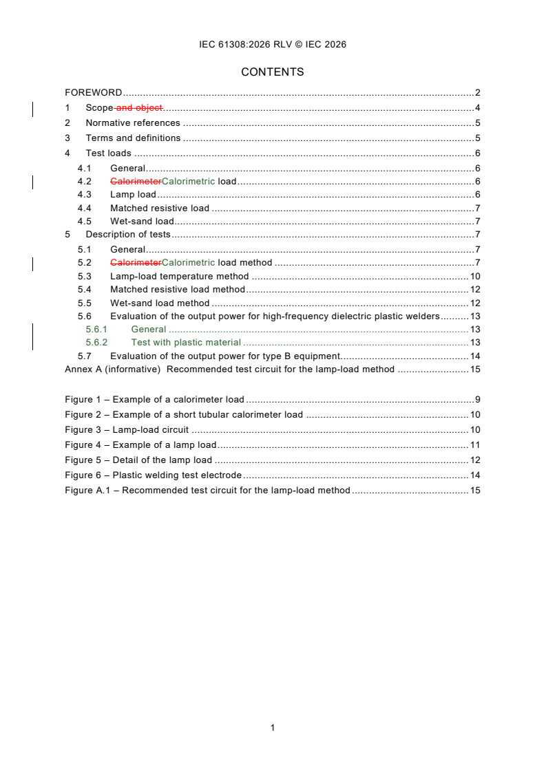
CONTENTS
FOREWORD . 2
1 Scope and object . 4
2 Normative references . 5
3 Terms and definitions . 5
4 Test loads . 6
4.1 General . 6
4.2 CalorimeterCalorimetric load . 6
4.3 Lamp load . 6
4.4 Matched resistive load . 7
4.5 Wet-sand load. 7
5 Description of tests . 7
5.1 General . 7
5.2 CalorimeterCalorimetric load method . 7
5.3 Lamp-load temperature method . 10
5.4 Matched resistive load method . 12
5.5 Wet-sand load method . 12
5.6 Evaluation of the output power for high-frequency dielectric plastic welders . 13
5.6.1 General . 13
5.6.2 Test with plastic material . 13
5.7 Evaluation of the output power for type B equipment . 14
Annex A (informative) Recommended test circuit for the lamp-load method . 15
Figure 1 – Example of a calorimeter load . 9
Figure 2 – Example of a short tubular calorimeter load . 10
Figure 3 – Lamp-load circuit . 10
Figure 4 – Example of a lamp load . 11
Figure 5 – Detail of the lamp load . 12
Figure 6 – Plastic welding test electrode . 14
Figure A.1 – Recommended test circuit for the lamp-load method . 15
INTERNATIONAL ELECTROTECHNICAL COMMISSION
____________
High-frequency dielectric heating installations -
Test methods for the determination of power output
FOREWORD
1) The International Electrotechnical Commission (IEC) is a worldwide organization for standardization comprising
all national electrotechnical committees (IEC National Committees). The object of IEC is to promote international
co-operation on all questions concerning standardization in the electrical and electronic fields. To this end and
in addition to other activities, IEC publishes International Standards, Technical Specifications, Technical Reports,
Publicly Available Specifications (PAS) and Guides (hereafter referred to as "IEC Publication(s)"). Their
preparation is entrusted to technical committees; any IEC National Committee interested in the subject dealt with
may participate in this preparatory work. International, governmental and non-governmental organizations liaising
with the IEC also participate in this preparation. IEC collaborates closely with the International Organization for
Standardization (ISO) in accordance with conditions determined by agreement between the two organizations.
2) The formal decisions or agreements of IEC on technical matters express, as nearly as possible, an international
consensus of opinion on the relevant subjects since each technical committee has representation from all
interested IEC National Committees.
3) IEC Publications have the form of recommendations for international use and are accepted by IEC National
Committees in that sense. While all reasonable efforts are made to ensure that the technical content of IEC
Publications is accurate, IEC cannot be held responsible for the way in which they are used or for any
misinterpretation by any end user.
4) In order to promote international uniformity, IEC National Committees undertake to apply IEC Publications
transparently to the maximum extent possible in their national and regional publications. Any divergence between
any IEC Publication and the corresponding national or regional publication shall be clearly indicated in the latter.
5) IEC itself does not provide any attestation of conformity. Independent certification bodies provide conformity
assessment services and, in some areas, access to IEC marks of conformity. IEC is not responsible for any
services carried out by independent certification bodies.
6) All users should ensure that they have the latest edition of this publication.
7) No liability shall attach to IEC or its directors, employees, servants or agents including individual experts and
members of its technical committees and IEC National Committees for any personal injury, property damage or
other damage of any nature whatsoever, whether direct or indirect, or for costs (including legal fees) and
expenses arising out of the publication, use of, or reliance upon, this IEC Publication or any other IEC
Publications.
8) Attention is drawn to the Normative references cited in this publication. Use of the referenced publications is
indispensable for the correct application of this publication.
9) IEC draws attention to the possibility that the implementation of this document may involve the use of (a)
patent(s). IEC takes no position concerning the evidence, validity or applicability of any claimed patent rights in
respect thereof. As of the date of publication of this document, IEC had not received notice of (a) patent(s), which
may be required to implement this document. However, implementers are cautioned that this may not represent
the latest information, which may be obtained from the patent database available at https://patents.iec.ch. IEC
shall not be held responsible for identifying any or all such patent rights.
This redline version of the official IEC Standard allows the user to identify the changes made
to the previous edition IEC 61308:2005. A vertical bar appears in the margin wherever a change
has been made. Additions are in green text, deletions are in strikethrough red text.
IEC 61308 has been prepared by IEC technical committee 27: Industrial electroheating and
electromagnetic processing. It is an International Standard.
This third edition cancels and replaces the second edition published in 2005. This edition
constitutes a technical revision.
This edition includes the following significant technical changes with respect to the previous
edition:
a) adaptation and alignment to the principles in more recent editions of IEC 60519-1 and
IEC 60519-6;
b) more detailed descriptions of, in particular, the calorimetric load test and output power
evaluation for dielectic plastic welders.
The text of this International Standard is based on the following documents:
Draft Report on voting
27/1244/FDIS 27/1248/RVD
Full information on the voting for its approval can be found in the report on voting indicated in
the above table.
The language used for the development of this International Standard is English.
This document was drafted in accordance with ISO/IEC Directives, Part 2, and developed in
accordance with ISO/IEC Directives, Part 1 and ISO/IEC Directives, IEC Supplement, available
at www.iec.ch/members_experts/refdocs. The main document types developed by IEC are
described in greater detail at www.iec.ch/publications.
The committee has decided that the contents of this document will remain unchanged until the
stability date indicated on the IEC website under webstore.iec.ch in the data related to the
specific document. At this date, the document will be
– reconfirmed,
– withdrawn, or
– revised.
1 Scope and object
This International Standard is applicable to industrial high-frequency dielectric heating
installations used for the purpose of thermal applications such as melting, drying, welding,
insect extermination, and gluing of partially conductive or non-conductive materials such as
plastics, wood, rubber, textiles, glass, ceramic, paper, bamboo or foodstuffs, in both normal
and protective atmospheres, using, for example, inert gases or vacuum.
This standard relates to high-frequency dielectric heating installations with nominal dielectric
heating frequency in the range from 1 MHz to 300 MHz with rated useful output power greater
than 50 W.
The main purpose of this standard is to assist in compliance with the requirements set out in
6.4 of IEC 60519-9 when testing electroheating power sources. It is not primarily intended as a
means of representing a potential high-frequency heating application for the requirement of the
user. Due to the large variety of dielectric heating applications, any output power value obtained
as a result of these tests should not always be taken as representing the power that can be
dissipated in a particular dielectric heating installation, but, in certain instances, the output
power value could be used as an indication of performance.
The power required to heat a charge is dependent, for example, on the type of material heated,
the temperature of heating and ambient moisture and on the construction of the electrode
system.
NOTE Heating a charge with dielectric parameters deeply changing in time and/or temperature the value of the
output power obtained with the actual charge may be different from that obtained in standard test conditions.
For equipment working outside the ITU-designated bands, the frequency of the generator follows the resonant
frequency of the output circuit, thus the output power can remain fairly stable during the work cycle, even with hand
tuning of the output circuit. Therefore, according to this standard, the test well represents the actual output power in
practical work conditions.
For equipment working in ITU-designated bands, the frequency of the generator remains stable, but the resonant
frequency of the output circuit varies with the change of dielectric parameters of the load. Therefore, the value of the
mean output power in the work cycle can be much lower than the value obtained in the test conditions. This value
depends on the time response of the eventual automatic tuning system.
This document specifies test methods for the determination of useful high frequency power
output in equipment for industrial heating and processing of materials. It is in particular
applicable to HF generators made available to users as separate units.
This document is basically applicable to equipment operating in the frequency range 100 kHz
to 300 MHz, as defined in IEC 60519-1, with the following limitations.
– This document does not apply to induction heating, which it is possible to carry out in the
lower part of the specified frequency band.
– The ISM centre frequencies for dielectric heating and processing of industrial interest are
narrow bands about 6,78 MHz, 13,56 MHz, 27,12 MHz and 40,68 MHz.
– This document is not applicable to:
• appliances for household and similar use;
• commercial use;
• laboratory use;
• medical high frequency equipment.
For equipment working in designated ISM bands, it is a legal requirement that the frequency
remains within the ISM bands according to CISPR 11, but the resonant frequency of the circuit
varies with the change of dielectric parameters of the load. Therefore, the value of the mean
output power in the work cycle can be much lower than the value obtained under the test
conditions. This value depends upon the response of the tuning system.
NOTE 1 The following criteria are suitable for determination of the classification as industrial equipment:
– commercial equipment is typically designed and planned for series production of many identical units;
– industrial equipment is typically produced in small series or even as single units; the processed goods are
consumed or ready for final use at the end of the heating process.
NOTE 2 Heating a workload with dielectric parameters which change significantly in time and/or with temperature,
the value of the output power obtained with the actual charge can be different from that obtained with the test load
specified in this document.
This document relates to equipment normally operating under continuous rated conditions.
2 Normative references
The following documents are referred to in the text in such a way that some or all of their content
constitutes requirements of this document. For dated references, only the edition cited applies.
For undated references, the latest edition of the referenced document (including any
amendments) applies.
IEC 60050-841:2004, International Electrotechnical Vocabulary (IEV) - Part 841: Industrial
electroheat
IEC 60519-1, Safety in installations for electroheating and electromagnetic processing - Part 1:
General requirements
IEC 60519-6, Safety in installations for electroheating and electromagnetic processing - Part 6:
Particular requirements for high frequency dielectric and microwave heating and processing
equipment
IEC 60519-9, Safety in electroheat installations – Part 9: Particular requirements for high -
frequency dielectric heating installations
3 Terms and definitions
For the purposes of this document, the terms and definitions given in IEC 60050-841 and
IEC 60519-9, IEC 60519-1, IEC 60519-6 and the following apply.
ISO and IEC maintain terminology databases for use in standardization at the following
addresses:
– IEC Electropedia: available at https://www.electropedia.org/
– ISO Online browsing platform: available at https://www.iso.org/obp
3.1
type A equipment
equipment with a dielectric heating the high frequency converter or
generator independent of, or separable from, the applicator to which the high-frequency
power is provided, for example, by a coaxial feeder
Note 1 to entry: The separation is by a coaxial line feeder or alternative means.
3.2
type B equipment
equipment with a dielectric heating the high frequency converter or generator
directly coupled to the applicator, for example, generator built into the plastic welding press, or
mounted on a tunnel oven
Note 1 to entry: In some cases, equipment with the dielectric heating generator directly connected to the heating
chamber and inseparable from it can be treated as type A equipment.
3.3
useful output power
maximum power as measured in a test load described in this standard
NOTE In this type, the output terminals of the generator are accessible, or the heating capacitor allows the use of
the wet-sand test. In certain cases, the parts of the gluing or welding press can be disconnected, allowing access to
the output terminals. The useful output power will be equal to, or greater than, the rated useful output power.
3.4
useful output power
high frequency power developed in the normal load
oscillating power calculated on the basis of measured values of voltages and currents
NOTE The design of such equipment does not allow the connection of a test load. Therefore, only evaluated useful
output power can be specified (see 5.7). For a particular kind of equipment, the output, for example, the number of
pieces heated per hour, may be given, or the output power can be evaluated by the plastic welding test electrode.
The useful output power will be equal to, or greater than, the rated useful output power.
3.5
plastic welding test electrode
cutting-edge welding electrode which typically consists of straight parallel parts separated by
20 mm, 2 mm broad, 20 mm high and as long as practically possible for the press used
4 Test loads
4.1 General
There are four different types of useful output power test loads used in high-frequency dielectric
heating installations. Only the main ones are outlined here. Specific constructions shall conform
to known engineering techniques. The test loads should be constructed so as to represent the
characteristics (e.g. dimensions, impedance) of the working normal load as closely as
practically possible.
The calorimeter calorimetric load, lamp load and resistive load allow the measurement of the
output power of the dielectric heating generator. The wet-sand load allows the measurement of
the useful output power of the dielectric heating installation (as defined in IEC 60519-9).
For plastic welders, the test with the electrode defined in 3.5 allows the evaluation of the output
power of the dielectric heating installation.
4.2 CalorimeterCalorimetric load
A calorimeter load is used for measuring the useful output power when the load is assumed to
be a combination of capacitance and resistance and for cases where the measured power is
about 1 kW or greater.
A calorimetric load is a substitute load for measuring output power to the normal load having
similar impedance to it. It is used for cases where the measured power is about 1 kW or greater.
4.3 Lamp load
The lamp load is used to measure useful output power of up to about 1 kW. A load consisting
of incandescent lamps is used according to 3.3 up to about 1 kW.The matching of the load is
accomplished by the selection of single-lamp power as well as by the connection of several
lamps in parallel or in series.
4.4 Matched resistive load
A matched resistive load can be used for applications where the load can be connected to the
high-frequency output terminals.
4.5 Wet-sand load
The load, which consists of a charge of wet sand placed in the heating capacitor, can be used
for some applications where the high-frequency output terminals of the generator are not
accessible.
This load consists of a charge of wet sand of similar impedance to the normal load. It is suitable
for some type B equipment and shall then be placed in the applicator in the same location as
the normal load.
5 Description of tests
5.1 General
Values of electromagnetic fields in places accessible to the personnel shall conform to national
and/or international safety regulations.
High-frequency electromagnetic fields should not affect measuring devices.
For all listed calorimetric methods, care shall be taken ensure that the outlet temperature is
measured as close as possible to the load in order to reduce heat losses.
5.2 CalorimeterCalorimetric load method
Typical examples are shown in Figure 1 and Figure 2, but variations of these designs are
acceptable. The measuring element is composed of low dielectric loss glass or a low power-
loss HF-transparent material and comprises two electrodes manufactured from a non-magnetic
material such as copper or aluminium.
The generator output terminals are connected to the two electrodes, with water serving as the
power-absorbing medium flows through the charge. The electrode spacing may can be
adjustable for load-matching purposes. To achieve the correct impedance matching between
the generator and the load, it may be is necessary to use the equipment's tuning circuit, in order
to obtain the required correct output power.
For class A equipment, the tuning circuit should be designed to minimise heat losses.
For class B equipment, the tuning circuit should be the same circuit as used during the intended
operation in order to achieve the correct impedance matching between the generator and the
load. It is typically necessary to retune to obtain the correct output power.
The procedure for testing the system is the following:
a) run the system with the normal load at the required power;
b) remove the normal load;
c) replace with the calorimetric load;
d) without significant adjustment to the tuning, or other controls (e.g. inductor/capacitor values,
electrode plate position etc.), adjust the impedance of the calorimetric load, to give the same
running conditions that were obtained for the actual load (without changing the tuning
settings significantly).
A recommended water flow rate is about 1 l per minute per kW but not less than 0,5 l per minute
per kW.
To avoid local water temperature hot spots through the charge workload, the water shall be
thoroughly mixed.
To avoid the formation of steam, which may can lead to explosion violent eruption, the water
flow should be monitored, for instance, by means of flow interlocking switches.
-1 -1 -1 -1
The specific conductivity of the water shall be between 0,002 Ω m and 0,006 Ω m .
The water inlet temperature shall not exceed 35 °C.
The water outlet temperature shall not exceed 60 °C.
The difference between the outlet temperature and the inlet temperature shall be at least 10 K
in order to obtain measurement results of acceptable accuracy.
The specific conductivity of the water shall be between 200 µS/cm and 600 µS/cm.
The measurement shall be carried out when the load is in thermal equilibrium.
The power output is calculated from Formula (1):
4,186 8 × QT×∆
P ≈ 0,07× QT×∆
(1)
where
P is the power output, in kW;
Q is the water flow rate, in l per minute;
∆T is the temperature difference between water inlet and outlet temperatures, in K.
NOTE 1 cal = 4,1 868 J.
The accuracy of the power output measurement shall be within ±5 %.
=
Key
1 electrodes
2 glass tubes
3 high-frequency terminals
4 water inlet from temperature measurement point
5 water outlet towards temperature measurement point
6 packing glands
7 screening case
Figure 1 – Example of a calorimeter load
Key
1 insulated tube fitted with water seals
2 aluminium top electrode
3 aluminium bottom electrode
4 water inlet
5 water outlet
6 insulated spacers
Figure 2 – Example of a short tubular calorimeter load
5.3 Lamp-load temperature method
A typical circuit for the lamp-load temperature method is shown in Figure 3. For loading of the
installation under test, several incandescent lamps in parallel constituting a load-lamp group
can be used. The load-lamp group h1 is connected to the output terminals of the generator. The
use of this method is possible when the output terminals of the generator are accessible. The
lamps are to be connected with leads of low inductance which are possibly equal and as short
as possible.
Key
K , K additional reactances
1 2
r regulated resistor
h1 lamp load
h2 comparison lamp
U mains voltage
n
U lamp voltage
h
U high-frequency voltage from generator
HF
I lamp current
h
Figure 3 – Lamp-load circuit
The number of lamps used depends on the rated output power of the equipment under test. The
lamps shall be capable of dissipating the rated output power. Lamps with short filament leads
are recommended.
A similar filament lamp h2 is then connected to an adjustable supply voltage of mains frequency.
The voltage is set to achieve the same lamp temperature as for h1. The voltage and current
through the lamp h2 are measured and their product gives the power dissipated which equals
the high-frequency output power of the high-frequency generator.
For frequencies above 30 MHz, this method is not recommended and, above 100 MHz,
practically not applicable. An example of a lamp load is shown in Figure 4. In this example, the
lamps are arranged concentrically so that the inductances of the lamp connections are
practically equal. The detail of the lamp load is shown in Figure 5.
NOTE In view of the dielectric strength and for better comparability, the lamps should be
operated at a maximum of 70 % of their rated voltage. Greater loading may be acceptable, but
occasional breakdown of some of the filaments may can occur. Lamps with a nominal power of
up to 100 W should be used. Lamps of up to 200 W can be used for lower frequencies.
Typical temperature measuring devices could can include photoelectric cells (see Annex A) or
pyrometers. The accuracy of the power output measurement shall be within ±5 %.
Key
1 circular earthed plate
2 plate under high-frequency voltage
3 earthed output terminal of the generator
4 connection to the "hot" output terminal of the generator
5 lamps forming a circle
Figure 4 – Example of a lamp load
Key
1 fragment of the circular earthed plate
2 plate under high-frequency voltage
3 brass tube with collar
4 E27 thread
5 silicon bronze spring
Figure 5 – Detail of the lamp load
5.4 Matched resistive load method
The matched resistive load is a low-reactance resistor cooled by natural air convection, by
forced air, or by water. It is generally connected to the generator by a coaxial feeder of
characteristic impedance of 50 Ω. Other feeders with different values of characteristic
impedances may be used.
The power is obtained by measuring the current or voltage at the resistor; the meter can directly
2 2
indicate the power as I R or V /R. The matched resistor loads are commercially available at
power levels from tens of watts to hundreds of kilowatts.
Typical accuracy is from ±2,5 % to ±5 % depending on the particular design.
5.5 Wet-sand load method
For the measurement of the output power by the use of wet-sand load, a flat low dielectric loss
glass or low dielectric loss plastic container or a metallic dish is placed in the heating capacitor
on the earthed electrode.
The necessary amount of sand is dried by any method, for example, in the heating capacitor,
and then cooled down to the ambient temperature.
A suitable amount of dry sand is put on the dish in the heating capacitor. Approximately 2 kg of
sand per 1 kW of the output power should be used. Approximately 1 kg of ordinary tap water at
ambient temperature per 1 kW of the output power is then added to the sand.
The installation under test is switched on, preferably on low power, matched quickly to the load
and switched into the maximum power, then switched off before all the water has evaporated.
The sand with the remaining water is then weighted again, and the amount of water at the end
of the test is established.
The inaccuracy of the power measurement obtained by this method is typically in the order of
±10 % to ±20 %. The actual estimated inaccuracy shall be noted in the report.
The high-frequency output power is calculated from Formula (2):
4,186 8 ××Q (100 − t ) 2 240 × (QQ− )
1 1 12
(2)
P +
TT
where
The accuracy of the power measurement obtained by this method is of the order of ± 10 % to
± 20 %.
P is the high-frequency output power, in kW;
is the mass of water at the beginning of the test, in kg;
Q
Q is the mass of water at the end of the test, in kg;
t is the ambient temperature at the beginning of the test, in K;
T is the time of heating of the test load at maximum power, in s.
NOTE 1 1 cal = 4,1868 J; heat of evaporation of water = 2 240 kJ/kg.
5.6 Evaluation of the output power for high-frequency dielectric plastic welders
5.6.1 General
For high-frequency dielectric plastic welders, when the output terminals of the generator are
accessible, the useful output power of the generator shall be measured by one of the methods
described in 5.2, 5.3 or 5.4. In certain cases, some parts of the press shall be removed for this
measurement.
5.6.2 Test with plastic material
If the output terminals of the generator are not accessible, the test with the dielectric cutting-
edge welding electrode defined in 3.5 can be performed. The dimensions of the test electrode
are shown in Figure 6. The par
...
IEC 61308 ®
Edition 3.0 2026-08
NORME
INTERNATIONALE
Installations de chauffage diélectrique à haute fréquence - Méthodes d'essai
pour la détermination de la puissance de sortie
ICS 25.180.10 ISBN 978-2-8327-1430-0
Droits de reproduction réservés. Sauf indication contraire, aucune partie de cette publication ne peut être reproduite ni
utilisée sous quelque forme que ce soit et par aucun procédé, électronique ou mécanique, y compris la photocopie et
les microfilms, sans l'accord écrit de l'IEC ou du Comité national de l'IEC du pays du demandeur. Si vous avez des
questions sur le copyright de l'IEC ou si vous désirez obtenir des droits supplémentaires sur cette publication, utilisez
les coordonnées ci-après ou contactez le Comité national de l'IEC de votre pays de résidence.
IEC Secretariat Tel.: +41 22 919 02 11
3, rue de Varembé info@iec.ch
CH-1211 Geneva 20 www.iec.ch
Switzerland
A propos de l'IEC
La Commission Electrotechnique Internationale (IEC) est la première organisation mondiale qui élabore et publie des
Normes internationales pour tout ce qui a trait à l'électricité, à l'électronique et aux technologies apparentées.
A propos des publications IEC
Le contenu technique des publications IEC est constamment revu. Veuillez vous assurer que vous possédez l’édition la
plus récente, un corrigendum ou amendement peut avoir été publié.
Recherche de publications IEC - IEC Products & Services Portal - products.iec.ch
webstore.iec.ch/advsearchform Découvrez notre puissant moteur de recherche et consultez
La recherche avancée permet de trouver des publications gratuitement tous les aperçus des publications, symboles
IEC en utilisant différents critères (numéro de référence, graphiques et le glossaire. Avec un abonnement, vous aurez
texte, comité d’études, …). Elle donne aussi des toujours accès à un contenu à jour adapté à vos besoins.
informations sur les projets et les publications remplacées
ou retirées. Electropedia - www.electropedia.org
Le premier dictionnaire d'électrotechnologie en ligne au
IEC Just Published - webstore.iec.ch/justpublished monde, avec plus de 22 500 articles terminologiques en
Restez informé sur les nouvelles publications IEC. Just anglais et en français, ainsi que les termes équivalents
dans 25 langues additionnelles. Egalement appelé
Published détaille les nouvelles publications parues.
Disponible en ligne et une fois par mois par email. Vocabulaire Electrotechnique International (IEV) en ligne.
Service Clients - webstore.iec.ch/csc
Si vous désirez nous donner des commentaires sur cette
publication ou si vous avez des questions contactez-
nous: sales@iec.ch.
SOMMAIRE
AVANT-PROPOS . 2
1 Domaine d'application . 4
2 Références normatives . 4
3 Termes et définitions . 5
4 Charges d'essai . 5
4.1 Généralités . 5
4.2 Charge calorimétrique . 6
4.3 Charge de la lampe . 6
4.4 Charge résistive adaptée . 6
4.5 Charge de sable humide . 6
5 Description des essais . 6
5.1 Généralités . 6
5.2 Méthode de la charge calorimétrique . 6
5.3 Méthode de la température à la lampe . 9
5.4 Méthode de la charge résistive adaptée . 11
5.5 Méthode de la charge de sable humide . 11
5.6 Évaluation de la puissance de sortie pour les soudeurs diélectriques en
plastique à haute fréquence . 12
5.6.1 Généralités . 12
5.6.2 Essai avec matière plastique . 12
5.7 Évaluation de la puissance de sortie pour les équipements de type B . 13
Annexe A (informative) Circuit d'essai recommandé pour la méthode à lampe . 14
Figure 1 – Exemple de charge calorimétrique . 8
Figure 2 – Exemple de charge calorimétrique tubulaire courte . 9
Figure 3 – Circuit de charge de lampe . 9
Figure 4 – Exemple de charge de lampe . 10
Figure 5 – Détail de la charge de la lampe . 11
Figure 6 – Électrode d'essai de soudage plastique. 13
Figure A.1 – Circuit d'essai recommandé pour la méthode à lampe . 14
COMMISSION ÉLECTROTECHNIQUE INTERNATIONALE
____________
Installations de chauffage diélectrique à haute fréquence -
Méthodes d'essai pour la détermination de la puissance de sortie
AVANT-PROPOS
1) La Commission Électrotechnique Internationale (IEC) est une organisation mondiale de normalisation composée
de l'ensemble des comités électrotechniques nationaux (Comités nationaux de l'IEC). L'IEC a pour objet de
favoriser la coopération internationale pour toutes les questions de normalisation dans les domaines de
l'électricité et de l'électronique. À cet effet, l'IEC – entre autres activités – publie des Normes internationales,
des Spécifications techniques, des Rapports techniques, des Spécifications accessibles au public (PAS) et des
Guides (ci-après dénommés "Publication(s) de l'IEC"). Leur élaboration est confiée à des comités d'études, aux
travaux desquels tout Comité national intéressé par le sujet traité peut participer. Les organisations
internationales, gouvernementales et non gouvernementales, en liaison avec l'IEC, participent également aux
travaux. L'IEC collabore étroitement avec l'Organisation Internationale de Normalisation (ISO), selon des
conditions fixées par accord entre les deux organisations.
2) Les décisions ou accords officiels de l'IEC concernant les questions techniques représentent, dans la mesure du
possible, un accord international sur les sujets étudiés, étant donné que les Comités nationaux de l'IEC intéressés
sont représentés dans chaque comité d'études.
3) Les Publications de l'IEC se présentent sous la forme de recommandations internationales et sont agréées
comme telles par les Comités nationaux de l'IEC. Tous les efforts raisonnables sont entrepris afin que l'IEC
s'assure de l'exactitude du contenu technique de ses publications; l'IEC ne peut pas être tenue responsable de
l'éventuelle mauvaise utilisation ou interprétation qui en est faite par un quelconque utilisateur final.
4) Dans le but d'encourager l'uniformité internationale, les Comités nationaux de l'IEC s'engagent, dans toute la
mesure possible, à appliquer de façon transparente les Publications de l'IEC dans leurs publications nationales
et régionales. Toutes divergences entre toutes Publications de l'IEC et toutes publications nationales ou
régionales correspondantes doivent être indiquées en termes clairs dans ces dernières.
5) L'IEC elle-même ne fournit aucune attestation de conformité. Des organismes de certification indépendants
fournissent des services d'évaluation de conformité et, dans certains secteurs, accèdent aux marques de
conformité de l'IEC. L'IEC n'est responsable d'aucun des services effectués par les organismes de certification
indépendants.
6) Tous les utilisateurs doivent s'assurer qu'ils sont en possession de la dernière édition de cette publication.
7) Aucune responsabilité ne doit être imputée à l'IEC, à ses administrateurs, employés, auxiliaires ou mandataires,
y compris ses experts particuliers et les membres de ses comités d'études et des Comités nationaux de l'IEC,
pour tout préjudice causé en cas de dommages corporels et matériels, ou de tout autre dommage de quelque
nature que ce soit, directe ou indirecte, ou pour supporter les coûts (y compris les frais de justice) et les dépenses
découlant de la publication ou de l'utilisation de cette Publication de l'IEC ou de toute autre Publication de l'IEC,
ou au crédit qui lui est accordé.
8) L'attention est attirée sur les références normatives citées dans cette publication. L'utilisation de publications
référencées est obligatoire pour une application correcte de la présente publication.
9) L'IEC attire l'attention sur le fait que la mise en application du présent document peut entraîner l'utilisation d'un
ou de plusieurs brevets. L'IEC ne prend pas position quant à la preuve, à la validité et à l'applicabilité de tout
droit de brevet revendiqué à cet égard. À la date de publication du présent document, l'IEC n'a pas reçu
notification qu'un ou plusieurs brevets pouvaient être nécessaires à sa mise en application. Toutefois, il y a lieu
d'avertir les responsables de la mise en application du présent document que des informations plus récentes
sont susceptibles de figurer dans la base de données de brevets, disponible à l'adresse https://patents.iec.ch.
L'IEC ne saurait être tenue pour responsable de ne pas avoir identifié de tels droits de brevets.
L'IEC 61308 a été établie par le comité d'études 27 de l'IEC: Chauffage électrique industriel et
traitement électromagnétique. Il s'agit d'une Norme internationale.
Cette troisième édition annule et remplace la deuxième édition parue en 2005. Cette édition
constitue une révision technique.
Cette édition inclut les modifications techniques significatives suivantes par rapport à l'édition
précédente:
a) l'adaptation et l'alignement sur les principes des éditions plus récentes de l'IEC 60519-1 et
de l'IEC 60519-6;
b) des descriptions plus détaillées, en particulier, de l'essai de charge calorimétrique et de
l'évaluation de la puissance de sortie pour les soudeurs plastiques diélectriques.
Le texte de la présente Norme internationale est issu des documents suivants:
Projet Rapport de vote
27/1244/FDIS 27/1248/RVD
Le rapport de vote indiqué dans le tableau ci-dessus donne toute information sur le vote ayant
abouti à son approbation.
La langue utilisée pour l'élaboration de la présente Norme internationale est l'anglais.
Le présent document a été rédigé conformément aux directives ISO/IEC, Partie 2, et élaboré
conformément aux directives ISO/IEC, Partie 1 et aux directives ISO/IEC, Supplément IEC,
disponibles à l’adresse www.iec.ch/members_experts/refdocs. Les principaux types de
documents développés par l'IEC sont décrits plus en détail à l'adresse www.iec.ch/publications.
Le comité a décidé que le contenu de ce document ne sera pas modifié avant la date de stabilité
indiquée sur le site web de l’IEC sous webstore.iec.ch dans les données relatives au document
spécifique. À cette date, le document sera
– reconduit,
– supprimé, ou
– révisé.
1 Domaine d'application
Le présent document spécifie des méthodes d'essai pour la détermination de la puissance de
sortie utile à haute fréquence dans les équipements de chauffage industriel et de traitement
des matériaux. Elle s'applique en particulier aux générateurs HF mis à la disposition des
utilisateurs sous forme d'unités séparées.
Le présent document est fondamentalement applicable aux matériels fonctionnant dans la
gamme de fréquences de 100 kHz à 300 MHz, comme défini dans l'IEC 60519-1, avec les
limitations suivantes.
– Le présent document ne s'applique pas au chauffage par induction, qu'il est possible
d'effectuer dans la partie inférieure de la bande de fréquences spécifiée.
– Les fréquences centrales ISM pour le chauffage diélectrique et le traitement d'intérêt
industriel sont des bandes étroites d'environ 6,78 MHz, 13,56 MHz, 27,12 MHz et
40,68 MHz.
– Le présent document n'est pas applicable:
• aux appareils à usage domestique et analogue;
• usage commercial;
• utilisation en laboratoire;
• appareils médicaux à haute fréquence.
Pour les matériels fonctionnant dans des bandes ISM désignées, il est une exigence légale que
la fréquence reste dans les bandes ISM selon la CISPR 11, mais la fréquence de résonance
du circuit varie avec la variation des paramètres diélectriques de la charge. Par conséquent, la
valeur de la puissance de sortie moyenne dans le cycle de travail peut être beaucoup plus faible
que la valeur obtenue dans les conditions d'essai. Cette valeur dépend de la réponse du
système de réglage.
NOTE 1 Les critères suivants conviennent pour la détermination de la classification en tant qu'équipement
industriel:
– les équipements commerciaux sont généralement conçus et planifiés pour la production en série de nombreuses
unités identiques;
– les équipements industriels sont généralement produits en petites séries ou même en unités individuelles; les
produits transformés sont consommés ou prêts à l'emploi final à la fin du processus de chauffage.
NOTE 2 En chauffant une charge de travail avec des paramètres diélectriques qui changent de manière significative
dans le temps et/ou avec la température, la valeur de la puissance de sortie obtenue avec la charge réelle peut être
différente de celle obtenue avec la charge d'essai spécifiée dans le présent document.
Le présent document concerne les équipements fonctionnant normalement dans des conditions
assignées continues.
2 Références normatives
Les documents suivants sont cités dans le texte de telle sorte qu'ils constituent, pour tout ou
partie de leur contenu, des exigences du présent document. Pour les références datées, seule
l'édition citée s'applique. Pour les références non datées, la dernière édition du document de
référence s'applique (y compris les éventuels amendements).
IEC 60050-841, Vocabulaire Électrotechnique International (VEI) - Partie 841: Électrothermie
industrielle
IEC 60519-1, Sécurité dans les installations destinées au traitement électrothermique et
électromagnétique - Partie 1: Exigences générales
IEC 60519-6, Sécurité dans les installations destinées au traitement électrothermique et
électromagnétique - Partie 6:. Exigences particulières pour les équipements de chauffage et de
traitement diélectriques à hautes fréquences et à hyperfréquences
3 Termes et définitions
Pour les besoins du présent document, les termes et définitions donnés dans l'IEC 60050-841,
l'IEC 60519-1, l'IEC 60519-6 ainsi que les suivants s'appliquent.
L'ISO et l'IEC tiennent à jour des bases de données terminologiques destinées à être utilisées
en normalisation aux adresses suivantes:
– IEC Electropedia: disponible à l'adresse https://www.electropedia.org/
– ISO Online browsing platform: disponible à l'adresse https://www.iso.org/obp
3.1
équipement de type A
équipement dont le convertisseur haute fréquence ou le générateur haute
fréquence est indépendant ou séparable de l'applicateur auquel la puissance haute fréquence
est fournie
Note 1 à l'article: La séparation est effectuée par un dispositif d'alimentation coaxial ou par d'autres moyens.
3.2
équipement de type B
équipement avec convertisseur haute fréquence ou générateur directement
couplé à l'applicateur, par exemple, intégré dans la presse à souder en plastique, ou monté sur
un four tunnel
Note 1 à l'article: Dans certains cas, un équipement dont le générateur de chauffage diélectrique est directement
relié à l'enceinte de chauffage et qui est inséparable de celle-ci peut êt
...