


IEC 62128-2:2003
(Main)Railway applications - Fixed installations - Part 2: Protective provisions against the effects of stray currents caused by d.c. traction systems
Railway applications - Fixed installations - Part 2: Protective provisions against the effects of stray currents caused by d.c. traction systems
Specifies requirements for protective provisions against the effects of stray currents which result from the operation of d.c. traction systems. Applies to all metallic fixed installations which form part of the traction system, and also to any other metallic components located in any position in the earth. Also applies to all new electrification of a d.c. railway system.
Applications ferroviaires - Installations fixes - Partie 2: Mesures de protection contre les effets des courants vagabonds issus de la traction électrique à courant continu
Spécifie les prescriptions relatives aux mesures de protection contre les effets des courants vagabonds issus du fonctionnement des systèmes de traction à courant continu. S'applique à toutes les installations fixes métalliques qui font partie du système de traction ainsi qu'à tout autre composant métallique placé au sol. S'applique également à toute nouvelle électrification d'un réseau ferroviaire à courant continu.
General Information
- Status
- Published
- Publication Date
- 05-Feb-2003
- Technical Committee
- TC 9 - Electrical equipment and systems for railways
- Current Stage
- DELPUB - Deleted Publication
- Start Date
- 16-Sep-2013
- Completion Date
- 14-Feb-2026
Relations
- Effective Date
- 05-Sep-2023
Overview
IEC 62128-2:2003 is an international standard developed by the International Electrotechnical Commission (IEC) that addresses the protection of fixed installations in railway applications from the adverse effects of stray currents caused by direct current (d.c.) traction systems. Stray currents can result in significant corrosion and deterioration of metallic structures that are part of or near the railway infrastructure. This standard specifies comprehensive requirements for implementing protective measures to minimize stray current effects, ensuring system reliability and the longevity of railway assets.
The standard is applicable to all metallic fixed installations within the traction system as well as any other metallic components located in the earth that could conduct stray currents. Importantly, it applies to all new electrification projects using d.c. traction systems, with its methodologies also being relevant to existing systems where stray current mitigation is deemed necessary.
Key Topics
IEC 62128-2:2003 covers several critical aspects related to the management and mitigation of stray currents in d.c. railway systems, including:
Scope of Application:
- Applies to railways, tramways, urban transit systems (including underground and elevated railways), mountain railways, trolleybus networks, magnetic levitation systems, and industrial material transport systems.
- Specifically excludes underground mine rail systems, cranes or mobile rail equipment, temporary structures, cable cars, funiculars, and routine maintenance work.
Stray Current and Corrosion:
- Defines stray current as current taking unintended paths, potentially causing electrochemical corrosion of embedded metals.
- Outlines the risk zones and mechanisms through which stray currents can damage railway infrastructure.
Protection Methods:
- Describes various methods for diverting or controlling stray currents, such as polarised drainage, forced drainage, and impressed current installations for cathodic protection.
- Specifies the importance of equipotential bonding and grounding arrangements.
Components and System Requirements:
- Addresses return circuits (running rails, return conductors, cables) and the role of insulating track formations.
- Sets criteria for the conductance (inverse of resistance) between rails and earth to minimize stray currents.
Testing, Verification, and Validation:
- Recommends measurement approaches for rail-to-earth conductance and verifying protective installation effectiveness.
- Guidance on validation and verification processes to ensure compliance.
Applications
IEC 62128-2 provides practical guidelines and technical requirements widely used in:
Design and Construction:
- Used by engineers and system designers during the planning and implementation of new d.c. electrified railway systems to ensure that stray current mitigation is integrated from project inception.
Asset Protection:
- Helps railway infrastructure managers extend the service life of metallic structures-including rails, bridges, tunnels, and depots-by minimizing corrosion risks.
Operation and Maintenance:
- Guides operators in monitoring and maintaining stray current protection systems, allowing for timely interventions and upgrades on existing networks.
Compliance and Risk Management:
- Serves as an essential reference for compliance with international best practices, risk assessments, and regulatory requirements related to stray current management in rail transport systems.
Related Standards
Several other standards are closely related to IEC 62128-2 and are beneficial for comprehensive stray current management:
- IEC 62128-1: Railway applications - Fixed installations - Part 1: Protective provisions relating to electrical safety and earthing
- IEC 60050-826: International Electrotechnical Vocabulary – Electrical installations of buildings
- ISO 15589: Petroleum and natural gas industries – Cathodic protection for pipeline transportation systems
By integrating IEC 62128-2:2003 with these related standards, railway professionals ensure robust protection of infrastructure against the detrimental impacts of stray currents, supporting safe, efficient, and reliable rail operations.
Get Certified
Connect with accredited certification bodies for this standard

IRIS Certification (UNIFE)
International Railway Industry Standard certification.

TÜV SÜD Rail GmbH
TÜV SÜD railway certification services.

Bureau Veritas Railway Certification
Railway and transportation certification.
Sponsored listings
Frequently Asked Questions
IEC 62128-2:2003 is a standard published by the International Electrotechnical Commission (IEC). Its full title is "Railway applications - Fixed installations - Part 2: Protective provisions against the effects of stray currents caused by d.c. traction systems". This standard covers: Specifies requirements for protective provisions against the effects of stray currents which result from the operation of d.c. traction systems. Applies to all metallic fixed installations which form part of the traction system, and also to any other metallic components located in any position in the earth. Also applies to all new electrification of a d.c. railway system.
Specifies requirements for protective provisions against the effects of stray currents which result from the operation of d.c. traction systems. Applies to all metallic fixed installations which form part of the traction system, and also to any other metallic components located in any position in the earth. Also applies to all new electrification of a d.c. railway system.
IEC 62128-2:2003 is classified under the following ICS (International Classification for Standards) categories: 45.060.01 - Railway rolling stock in general. The ICS classification helps identify the subject area and facilitates finding related standards.
IEC 62128-2:2003 has the following relationships with other standards: It is inter standard links to IEC 62128-2:2013. Understanding these relationships helps ensure you are using the most current and applicable version of the standard.
IEC 62128-2:2003 is available in PDF format for immediate download after purchase. The document can be added to your cart and obtained through the secure checkout process. Digital delivery ensures instant access to the complete standard document.
Standards Content (Sample)
NORME CEI
INTERNATIONALE IEC
62128-2
INTERNATIONAL
Première édition
STANDARD
First edition
2003-02
Applications ferroviaires –
Installations fixes –
Partie 2:
Mesures de protection contre les effets
des courants vagabonds issus de la traction
électrique à courant continu
Railway applications –
Fixed installations –
Part 2:
Protective provisions against the effects
of stray currents caused by d.c. traction
systems
Numéro de référence
Reference number
CEI/IEC 62128-2:2003
Numérotation des publications Publication numbering
Depuis le 1er janvier 1997, les publications de la CEI As from 1 January 1997 all IEC publications are
sont numérotées à partir de 60000. Ainsi, la CEI 34-1 issued with a designation in the 60000 series. For
devient la CEI 60034-1. example, IEC 34-1 is now referred to as IEC 60034-1.
Editions consolidées Consolidated editions
Les versions consolidées de certaines publications de la The IEC is now publishing consolidated versions of its
CEI incorporant les amendements sont disponibles. Par publications. For example, edition numbers 1.0, 1.1
exemple, les numéros d’édition 1.0, 1.1 et 1.2 indiquent and 1.2 refer, respectively, to the base publication,
respectivement la publication de base, la publication de the base publication incorporating amendment 1 and
base incorporant l’amendement 1, et la publication de the base publication incorporating amendments 1
base incorporant les amendements 1 et 2. and 2.
Informations supplémentaires Further information on IEC publications
sur les publications de la CEI
Le contenu technique des publications de la CEI est The technical content of IEC publications is kept
constamment revu par la CEI afin qu'il reflète l'état under constant review by the IEC, thus ensuring that
actuel de la technique. Des renseignements relatifs à the content reflects current technology. Information
cette publication, y compris sa validité, sont dispo- relating to this publication, including its validity, is
nibles dans le Catalogue des publications de la CEI available in the IEC Catalogue of publications
(voir ci-dessous) en plus des nouvelles éditions, (see below) in addition to new editions, amendments
amendements et corrigenda. Des informations sur les and corrigenda. Information on the subjects under
sujets à l’étude et l’avancement des travaux entrepris consideration and work in progress undertaken by the
par le comité d’études qui a élaboré cette publication, technical committee which has prepared this
ainsi que la liste des publications parues, sont publication, as well as the list of publications issued,
également disponibles par l’intermédiaire de: is also available from the following:
• Site web de la CEI (www.iec.ch) • IEC Web Site (www.iec.ch)
• Catalogue des publications de la CEI • Catalogue of IEC publications
Le catalogue en ligne sur le site web de la CEI The on-line catalogue on the IEC web site
(http://www.iec.ch/searchpub/cur_fut.htm) vous permet (http://www.iec.ch/searchpub/cur_fut.htm) enables
de faire des recherches en utilisant de nombreux you to search by a variety of criteria including text
critères, comprenant des recherches textuelles, par searches, technical committees and date of
comité d’études ou date de publication. Des publication. On-line information is also available
informations en ligne sont également disponibles sur on recently issued publications, withdrawn and
les nouvelles publications, les publications rempla- replaced publications, as well as corrigenda.
cées ou retirées, ainsi que sur les corrigenda.
• IEC Just Published • IEC Just Published
Ce résumé des dernières publications parues This summary of recently issued publications
(http://www.iec.ch/online_news/justpub/jp_entry.htm) (http://www.iec.ch/online_news/justpub/jp_entry.htm)
est aussi disponible par courrier électronique. is also available by email. Please contact the
Veuillez prendre contact avec le Service client Customer Service Centre (see below) for further
(voir ci-dessous) pour plus d’informations. information.
• Service clients • Customer Service Centre
Si vous avez des questions au sujet de cette If you have any questions regarding this
publication ou avez besoin de renseignements publication or need further assistance, please
supplémentaires, prenez contact avec le Service contact the Customer Service Centre:
clients:
Email: custserv@iec.ch Email: custserv@iec.ch
Tél: +41 22 919 02 11 Tel: +41 22 919 02 11
Fax: +41 22 919 03 00 Fax: +41 22 919 03 00
.
NORME CEI
INTERNATIONALE IEC
62128-2
INTERNATIONAL
Première édition
STANDARD
First edition
2003-02
Applications ferroviaires –
Installations fixes –
Partie 2:
Mesures de protection contre les effets
des courants vagabonds issus de la traction
électrique à courant continu
Railway applications –
Fixed installations –
Part 2:
Protective provisions against the effects
of stray currents caused by d.c. traction
systems
IEC 2003 Droits de reproduction réservés Copyright - all rights reserved
Aucune partie de cette publication ne peut être reproduite ni No part of this publication may be reproduced or utilized in any
utilisée sous quelque forme que ce soit et par aucun procédé, form or by any means, electronic or mechanical, including
électronique ou mécanique, y compris la photocopie et les photocopying and microfilm, without permission in writing from
microfilms, sans l'accord écrit de l'éditeur. the publisher.
International Electrotechnical Commission, 3, rue de Varembé, PO Box 131, CH-1211 Geneva 20, Switzerland
Telephone: +41 22 919 02 11 Telefax: +41 22 919 03 00 E-mail: inmail@iec.ch Web: www.iec.ch
CODE PRIX
T
Commission Electrotechnique Internationale PRICE CODE
International Electrotechnical Commission
Международная Электротехническая Комиссия
Pour prix, voir catalogue en vigueur
For price, see current catalogue
– 2 – 62128-2 © CEI:2003
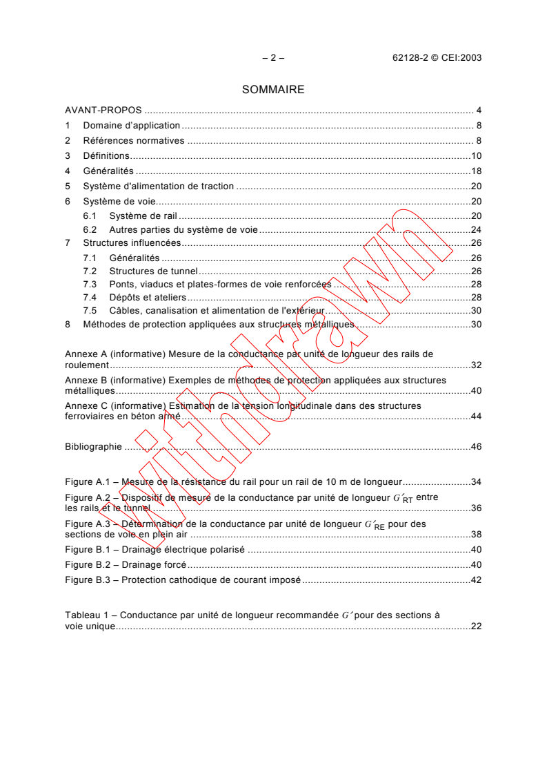
SOMMAIRE
AVANT-PROPOS . 4
1 Domaine d’application . 8
2 Références normatives . 8
3 Définitions.10
4 Généralités .18
5 Système d'alimentation de traction .20
6 Système de voie.20
6.1 Système de rail .20
6.2 Autres parties du système de voie.24
7 Structures influencées.26
7.1 Généralités .26
7.2 Structures de tunnel.26
7.3 Ponts, viaducs et plates-formes de voie renforcées .28
7.4 Dépôts et ateliers.28
7.5 Câbles, canalisation et alimentation de l'extérieur.30
8 Méthodes de protection appliquées aux structures métalliques .30
Annexe A (informative) Mesure de la conductance par unité de longueur des rails de
roulement.32
Annexe B (informative) Exemples de méthodes de protection appliquées aux structures
métalliques.40
Annexe C (informative) Estimation de la tension longitudinale dans des structures
ferroviaires en béton armé.44
Bibliographie .46
Figure A.1 – Mesure de la résistance du rail pour un rail de 10 m de longueur.34
Figure A.2 – Dispositif de mesure de la conductance par unité de longueur G′ entre
RT
les rails et le tunnel .36
Figure A.3 – Détermination de la conductance par unité de longueur G′ pour des
RE
sections de voie en plein air .38
Figure B.1 – Drainage électrique polarisé .40
Figure B.2 – Drainage forcé.40
Figure B.3 – Protection cathodique de courant imposé.42
Tableau 1 – Conductance par unité de longueur recommandée G′ pour des sections à
voie unique.22
62128-2 © IEC:2003 – 3 –
CONTENTS
FOREWORD . 5
1 Scope . 9
2 Normative references. 9
3 Definitions.11
4 General.19
5 Traction power supply system .21
6 Track system .21
6.1 Rail system .21
6.2 Other parts of the track system .25
7 Influenced structures.27
7.1 General .27
7.2 Tunnel structures .27
7.3 Bridges, viaducts and reinforced trackbed .29
7.4 Depots and workshops.29
7.5 Cables, pipework and power supply from outside.31
8 Protection methods applied to metallic structures .31
Annex A (informative) Measurement of the conductance per unit length
of the running rails.33
Annex B (informative) Examples for protection methods applied to metallic structures.41
Annex C (informative) Estimation of the longitudinal voltage in reinforced concrete
railway structures .45
Bibliography .47
Figure A.1 – Measurement of the rail resistance for a rail of 10 m length.35
Figure A.2 – Measuring arrangement for the conductance per unit length G′ between
RT
rails and tunnel.37
Figure A.3 – Determination of the conductance per unit length G′ for track sections in
RE
open air.39
Figure B.1 – Polarised electric drainage.41
Figure B.2 – Forced drainage .41
Figure B.3 – Impressed current cathodic protection.43
Table 1 – Recommended conductance per unit length G´ for single track sections .23
– 4 – 62128-2 © CEI:2003
COMMISSION ÉLECTROTECHNIQUE INTERNATIONALE
____________
APPLICATIONS FERROVIAIRES –
INSTALLATIONS FIXES –
Partie 2: Mesures de protection contre les effets des courants vagabonds
issus de la traction électrique à courant continu
AVANT-PROPOS
1) La CEI (Commission Électrotechnique Internationale) est une organisation mondiale de normalisation composée
de l'ensemble des comités électrotechniques nationaux (Comités nationaux de la CEI). La CEI a pour objet de
favoriser la coopération internationale pour toutes les questions de normalisation dans les domaines de
l'électricité et de l'électronique. A cet effet, la CEI, entre autres activités, publie des Normes internationales.
Leur élaboration est confiée à des comités d'études, aux travaux desquels tout Comité national intéressé par le
sujet traité peut participer. Les organisations internationales, gouvernementales et non gouvernementales, en
liaison avec la CEI, participent également aux travaux. La CEI collabore étroitement avec l'Organisation
Internationale de Normalisation (ISO), selon des conditions fixées par accord entre les deux organisations.
2) Les décisions ou accords officiels de la CEI concernant les questions techniques représentent, dans la mesure
du possible, un accord international sur les sujets étudiés, étant donné que les Comités nationaux intéressés
sont représentés dans chaque comité d’études.
3) Les documents produits se présentent sous la forme de recommandations internationales. Ils sont publiés
comme normes, spécifications techniques, rapports techniques ou guides et agréés comme tels par les Comités
nationaux.
4) Dans le but d'encourager l'unification internationale, les Comités nationaux de la CEI s'engagent à appliquer de
façon transparente, dans toute la mesure possible, les Normes internationales de la CEI dans leurs normes
nationales et régionales. Toute divergence entre la norme de la CEI et la norme nationale ou régionale
correspondante doit être indiquée en termes clairs dans cette dernière.
5) La CEI n’a fixé aucune procédure concernant le marquage comme indication d’approbation et sa responsabilité
n’est pas engagée quand un matériel est déclaré conforme à l’une de ses normes.
6) L’attention est attirée sur le fait que certains des éléments de la présente Norme internationale peuvent faire
l’objet de droits de propriété intellectuelle ou de droits analogues. La CEI ne saurait être tenue pour
responsable de ne pas avoir identifié de tels droits de propriété et de ne pas avoir signalé leur existence.
La Norme internationale CEI 62128-2 a été établie par le comité d'études 9 de la CEI: Matériel
électrique ferroviaire.
Le texte de cette norme est issu des documents suivants:
FDIS Rapport de vote
9/719/FDIS 9/736/RVD
Le rapport de vote indiqué dans le tableau ci-dessus donne toute information sur le vote ayant
abouti à l'approbation de cette norme.
Cette publication a été rédigée selon les Directives ISO/CEI, Partie 2.
La CEI 62128 comprend les parties suivantes, présentées sous le titre général Applications
ferroviaires – Installations fixes:
Partie 1: Mesures de protection relatives à la sécurité électrique et à la mise à la terre
Partie 2: Mesures de protection contre les effets des courants vagabonds issus de la traction
électrique à courant continu
62128-2 © IEC:2003 – 5 –
INTERNATIONAL ELECTROTECHNICAL COMMISSION
___________
RAILWAY APPLICATIONS –
FIXED INSTALLATIONS –
Part 2: Protective provisions against the effects
of stray currents caused by d.c. traction systems
FOREWORD
1) The IEC (International Electrotechnical Commission) is a worldwide organization for standardization comprising
all national electrotechnical committees (IEC National Committees). The object of the IEC is to promote
international co-operation on all questions concerning standardization in the electrical and electronic fields. To
this end and in addition to other activities, the IEC publishes International Standards. Their preparation is
entrusted to technical committees; any IEC National Committee interested in the subject dealt with may
participate in this preparatory work. International, governmental and non-governmental organizations liaising
with the IEC also participate in this preparation. The IEC collaborates closely with the International Organization
for Standardization (ISO) in accordance with conditions determined by agreement between the two
organizations.
2) The formal decisions or agreements of the IEC on technical matters express, as nearly as possible, an
international consensus of opinion on the relevant subjects since each technical committee has representation
from all interested National Committees.
3) The documents produced have the form of recommendations for international use and are published in the form
of standards, technical specifications, technical reports or guides and they are accepted by the National
Committees in that sense.
4) In order to promote international unification, IEC National Committees undertake to apply IEC International
Standards transparently to the maximum extent possible in their national and regional standards. Any
divergence between the IEC Standard and the corresponding national or regional standard shall be clearly
indicated in the latter.
5) The IEC provides no marking procedure to indicate its approval and cannot be rendered responsible for any
equipment declared to be in conformity with one of its standards.
6) Attention is drawn to the possibility that some of the elements of this International Standard may be the subject
of patent rights. The IEC shall not be held responsible for identifying any or all such patent rights.
International Standard IEC 62128-2 has been prepared by IEC technical committee 9: Electric
railway equipment.
The text of this standard is based on the following documents:
FDIS Reports on voting
9/719/FDIS 9/736/RVD
Full information on the voting for the approval of this standard can be found in the report on
voting indicated in the above table.
This publication has been drafted in accordance with the ISO/IEC Directives, Part 2.
IEC 62128 consists of the following parts, under the general title Railway applications – Fixed
installations:
Part 1: Protective provisions relating to electrical safety and earthing
Part 2: Protective provisions against the effects of stray currents caused by d.c. traction
systems
– 6 – 62128-2 © CEI:2003
Le comité a décidé que le contenu de cette publication ne sera pas modifié avant 2008. A cette
date, la publication sera
• reconduite;
• supprimée;
• remplacée par une édition révisée, ou
• amendée.
62128-2 © IEC:2003 – 7 –
The committee has decided that the contents of this publication will remain unchanged until
2008. At this date, the publication will be
• reconfirmed;
• withdrawn;
• replaced by a revised edition, or
• amended.
– 8 – 62128-2 © CEI:2003
APPLICATIONS FERROVIAIRES –
INSTALLATIONS FIXES –
Partie 2: Mesures de protection contre les effets des courants vagabonds
issus de la traction électrique à courant continu
1 Domaine d’application
La présente partie de la CEI 62128 spécifie les prescriptions relatives aux mesures de
protection contre les effets des courants vagabonds issus du fonctionnement des systèmes de
traction à courant continu.
L'expérience acquise depuis de nombreuses années n'ayant pas démontré d'effets corrosifs
évidents dus aux systèmes de traction à courant alternatif et les recherches actuelles n'étant
pas terminées, la présente norme traite uniquement des courants vagabonds issus des
systèmes de traction à courant continu.
La présente norme s'applique à toutes les installations fixes métalliques qui font partie du
système de traction ainsi qu'à tout autre composant métallique placé au sol quelle que soit sa
position et qui peut transporter des courants vagabonds issus de l'exploitation du réseau
ferroviaire.
La présente norme s'applique à toute nouvelle électrification d'un réseau ferroviaire à courant
continu. Ses principes peuvent également s'appliquer aux systèmes électrifiés existants
lorsqu'il est nécessaire de tenir compte des effets des courants vagabonds.
La gamme d'application comprend:
– les voies ferrées;
– les systèmes de transport en commun guidés tels que: les tramways, les chemins de fer
aériens et souterrains, les chemins de fer de montagne, les systèmes de trolleybus et
les systèmes à sustentation magnétique;
– les systèmes de transport de marchandises.
La présente norme ne s'applique pas:
a) aux systèmes de traction miniers utilisés dans les mines souterraines;
b) aux grues, transbordeurs et équipements similaires sur rail, aux structures provisoires (par
exemple des structures pour expositions) dans la mesure où ces équipements ne sont pas
directement alimentés par le système de lignes de contact et ne sont pas menacés par le
système d'alimentation de traction;
c) aux téléphériques, télécabines;
d) aux funiculaires;
e) aux travaux de maintenance.
2 Références normatives
Les documents de référence suivants sont indispensables pour l'application du présent
document. Pour les références datées, seule l'édition citée s'applique. Pour les références non
datées, la dernière édition du document de référence s'applique (y compris les éventuels
amendements).
62128-2 © IEC:2003 – 9 –
RAILWAY APPLICATIONS –
FIXED INSTALLATIONS –
Part 2: Protective provisions against the effects
of stray currents caused by d.c. traction systems
1 Scope
This part of IEC 62128 specifies requirements for protective provisions against the effects of
stray currents which result from the operation of d.c. traction systems.
As the experience of several decades has not shown evident corrosion effects from a.c.
traction systems and actual investigations are not completed, this standard only deals with
stray currents flowing from a d.c. traction system.
This standard applies to all metallic fixed installations which form part of the traction system,
and also to any other metallic components located in any position in the earth, which may carry
stray currents resulting from the operation of the railway system.
This standard applies to all new electrification of a d.c. railway system. The principles may
also be applied to existing electrified systems where it is necessary to consider the effects of
stray currents.
The range of application includes:
– railways;
– guided mass transport systems such as: tramways, elevated and underground railways,
mountain railways, trolleybus systems and magnetic levitated systems;
– material transportation systems.
This standard does not apply to:
a) mine traction systems in underground mines;
b) cranes, transportable platforms and similar transportation equipment on rails, temporary
structures (for example exhibition structures) in so far as these are not supplied directly
from the contact line system and are not endangered by the traction power supply system;
c) suspended cable cars;
d) funicular railways;
e) maintenance work.
2 Normative references
The following referenced documents are indispensable for the application of this document.
For dated references, only the edition cited applies. For undated references, the latest edition
of the referenced document (including any amendments) applies.
– 10 – 62128-2 © CEI:2003
CEI 60050-826, Vocabulaire Electrotechnique International (VEI) – Chapitre 826: Installations
électriques des bâtiments
CEI 62128-1, Applications ferroviaires – Installations fixes – Partie 1: Mesures de protection
relatives à la sécurité électrique et à la mise à la terre
ISO/CD 15589, Industries du pétrole et du gaz naturel – Protection cathodique pour systèmes
de transport par conduites
3 Définitions
Pour les besoins de la présente partie de la CEI 62128, les définitions suivantes s’appliquent:
3.1
courant vagabond
courant qui suit des itinéraires autres que les itinéraires prévus
3.2
zone de courant vagabond
zone dans laquelle des courants peuvent être échangés entre un système de traction à courant
continu et des structures métalliques ou la terre
NOTE Il est admis qu'une zone de courant vagabond s'étende sur une distance de quelques kilomètres.
3.3
corrosion
réaction chimique ou électrochimique d'un métal avec son environnement, entraînant sa
dégradation ou sa destruction progressive
NOTE La présente norme traite de la corrosion par réaction électrochimique.
3.4
protection cathodique
méthode de protection d'un métal contre les attaques dues à la corrosion en faisant circuler un
courant continu de son environnement électrolytique dans l'ensemble de la surface du métal
3.4.1
drainage électrique polarisé
drainage polarisé
forme de drainage des courants vagabonds dans laquelle la connexion entre une structure
protégée et un système de traction comprend un ou plusieurs dispositifs unidirectionnels tels
qu'un redresseur ou un relais et un contacteur
3.4.2
drainage forcé
forme de drainage dans laquelle la connexion entre une structure protégée et un système de
traction comprend une source de courant continu indépendante
3.4.3
installation à courant imposé
redresseur ou autre source de courant continu alimentant une structure protégée afin d'obtenir
le potentiel de protection nécessaire
3.5
potentiel de protection
niveau le plus négatif auquel le potentiel d'une structure métallique, par rapport à une
électrode de référence spécifiée dans un environnement électrolytique, doit être abaissé pour
assurer une protection cathodique de la structure
62128-2 © IEC:2003 – 11 –
IEC 60050-826, International Electrotechnical Vocabulary – Chapter 826: Electrical installations
of buildings
IEC 62128-1, Railway Applications – Fixed installations – Part 1: Protective provisions relating
to electrical safety and earthing
ISO/CD 15589, Petroleum and natural gas industries – Cathodic protection for pipeline
transportation systems
3 Definitions
For the purposes of this part of IEC 62128, the following definitions apply:
3.1
stray current
current which follows paths other than the intended paths
3.2
stray current zone
zone in which currents may be exchanged between a d.c. traction system and metallic
structures or earth
NOTE Such a stray current zone may extend over a distance of a few kilometres.
3.3
corrosion
chemical or electrochemical reaction of a metal with its environment, resulting in its
progressive degradation or destruction
NOTE This standard deals with corrosion by electrochemical reaction.
3.4
cathodic protection
method to protect a metal from corrosive attack by causing a direct current to flow from its
electrolytic environment into the entire metal surface
3.4.1
polarised electric drainage
polarised drainage
form of drainage of stray currents in which the connection between a protected structure and a
traction system includes a unidirectional device or devices such as a rectifier or a relay and
contactor
3.4.2
forced drainage
form of drainage in which the connection between a protected structure and a traction system
includes an independent source of direct current
3.4.3
impressed current installation
rectifier or other d.c. source supplying direct current to a protected structure in order to achieve
the necessary protection potential
3.5
protection potential
most negative level to which the potential of a metallic structure, with respect to a specified
reference electrode in an electrolytic environment, has to be depressed in order to effect
cathodic protection of the structure
– 12 – 62128-2 © CEI:2003
3.6
circuit de retour
ensemble des conducteurs qui constituent l'itinéraire prévu pour le courant de retour de
traction et le courant dans des conditions de défaut
NOTE Les conducteurs peuvent être par exemple:
– les rails de roulement;
– les rails de retour de courant;
– les conducteurs de retour;
– les câbles de retour.
3.7
système à retour par la voie
système dans lequel les rails de roulement de la voie constituent une partie du circuit de retour
3.8
conducteur de retour
conducteur acheminé parallèlement à la voie et relié aux rails de roulement à intervalles
réguliers
3.9
rail de retour de courant
rail de contact utilisé pour le courant de retour de traction en lieu et place des rails de
roulement
3.10
câble de retour
conducteur de retour isolé faisant partie du circuit de retour et reliant le reste du circuit de
retour à la sous-station
3.11
barre collectrice du câble de retour
barre collectrice située dans les sous-stations et à laquelle se terminent les câbles de retour
3.12
sous-station (de traction) à courant continu
installation dont la principale fonction est d'alimenter un système de ligne de contact et dans
laquelle la tension d'un système d'alimentation primaire est convertie à la tension de la ligne de
contact
3.13
courant de retour de traction
somme des courants de traction retournant à la source d'alimentation
NOTE Il est admis que la source d'alimentation soit un véhicule régénérateur.
3.14
connexion électrique de rails
conducteur ayant pour but d'assurer la continuité électrique des rails au droit d'un joint
3.15
éclisse isolante
joint mécanique des rails les séparant galvaniquement dans le sens longitudinal
3.16
connexion croisée inter-rails
connexion électrique qui relie les rails de roulement de la même voie
62128-2 © IEC:2003 – 13 –
3.6
return circuit
all conductors which form the intended path for the traction return current and the current
under fault conditions
NOTE The conductors may be for example:
– running rails;
– return conductor rails;
– return conductors;
– return cables.
3.7
track return system
system in which the running rails form a part of the return circuit
3.8
return conductor
conductor, which parallels the track and which is connected to the running rails at periodic
intervals
3.9
return conductor rail
conductor rail used instead of the running rails for the traction return current
3.10
return cable
insulated return conductor forming part of the return circuit and connecting the rest of the
return circuit to the substation
3.11
return cable busbar
busbar in substations at which return cables terminate
3.12
d.c. (traction) substation
installation the main function of which is to supply a contact line system, at which the voltage of
a primary supply system is converted to the voltage of the contact line
3.13
traction return current
sum of the traction currents returning to the supply source
NOTE The supply source may be a regenerating vehicle.
3.14
rail joint bond
conductor ensuring the electrical continuity of a rail at a joint
3.15
insulated rail joint
mechanical rail joint which longitudinally separates the rail electrically
3.16
rail-to-rail cross bond
electrical bond that interconnects the running rails of the same track
– 14 – 62128-2 © CEI:2003
3.17
connexion croisée inter-voies
connexion électrique qui relie des voies entre elles
3.18
terre
masse conductrice de la terre, dont le potentiel électrique en chaque point est pris, par
convention, égal à zéro
[VEI 826-04-01]
3.19
prise de terre
corps conducteur, ou ensemble de corps conducteurs en contact intime avec le sol et assurant
une liaison électrique avec celui-ci
[VEI 826-04-02]
3.20
terre de tunnel
interconnexion électrique des tiges de renfort de tunnels en béton armé et, dans le cas
d'autres modes de construction, interconnexion conductrice des parties métalliques du tunnel
3.21
terre de structure
interconnexion électrique des tiges de renfort de structures et, dans le cas d'autres modes de
construction, interconnexion conductrice des parties métalliques
NOTE Les structures ferroviaires armées telles que ponts, viaducs et plates-formes de voie renforcées en sont
des exemples.
3.22
résistance rail-terre
résistance électrique entre les rails de roulement et la terre
NOTE 1 Pour des systèmes de traction à courant continu en tunnel, la mesure est effectuée entre les rails de
roulement et la terre du tunnel.
NOTE 2 Sauf indication contraire et explicite, dans la présente norme, la résistance rail-terre fait référence à une
installation à voie unique.
3.23
conductance par unité de longueur
valeur inverse de la résistance rail-terre par unité de longueur
NOTE Sauf indication contraire et explicite, dans la présente norme, la conductance par unité de longueur fait
référence à une installation à voie unique.
3.24
liaison équipotentielle
liaison électrique mettant au même potentiel, ou à des potentiels voisins, des masses et des
éléments conducteurs
[VEI 826-04-09]
3.25
conducteur d'équipotentialité
conducteur de protection assurant une liaison équipotentielle
[VEI 826-04-10]
62128-2 © IEC:2003 – 15 –
3.17
track-to-track cross bond
electrical bond that interconnects tracks
3.18
earth
conductive mass of the earth, whose electric potential at any point is conventionally taken as
zero
[IEV 826-04-01]
3.19
earth electrode
conductive part or a group of conductive parts in intimate contact with and providing an
electrical connection with the earth
[IEV 826-04-02]
3.20
tunnel earth
electrical interconnection of the reinforcing rods of reinforced concrete tunnels, and in the case
of other modes of construction, the conductive interconnection of the metallic parts of the
tunnel
3.21
structure earth
electrical interconnection of the reinforcing rods of structures, and in the case of other modes
of construction, the conductive interconnection of the metallic parts
NOTE Examples are reinforced railway structures such as bridges, viaducts and reinforced track beds.
3.22
rail to earth resistance
electrical resistance between the running rails and the earth
NOTE 1 For d.c. traction systems in tunnels, the measurement is made between the running rails and tunnel
earth.
NOTE 2 In this standard, the rail to earth resistance refers to a single-track installation, unless otherwise explicitly
specified.
3.23
conductance per unit length
reciprocal value of the rail to earth resistance per unit of length
NOTE In this standard, the conductance per unit length refers to a single-track installation, unless otherwise
explicitly specified.
3.24
equipotential bonding
electrical connection putting various exposed conductive parts and extraneous conductive parts
at a substantially equal potential
[IEV 826-04-09]
3.25
equipotential bonding conductor
protective conductor for ensuring equipotential bonding
[IEV 826-04-10]
– 16 – 62128-2 © CEI:2003
3.26
potentiel du rail
tension apparaissant dans des conditions d'exploitation, lorsque les rails de roulement sont
utilisés pour transporter le courant de retour de traction ou, dans des conditions de défaut,
entre les rails de roulement et la terre
3.27
tension de contact (équivalente)
tension apparaissant, dans des conditions de défaut, entre des parties touchées simul-
tanément
NOTE La valeur de la tension de contact équivalente peut être substantiellement affectée par l'impédance de la
personne en contact avec ces parties.
3.28
tension accessible
dans des conditions d'exploitation, partie du potentiel du rail qui peut être pontée par des
personnes, le trajet conducteur étant conventionnellement d'une main aux deux pieds à travers
le corps ou d'une main à l'autre (distance horizontale d'un mètre par rapport à une partie
accessible)
3.29
plate-forme fermée
zone où le niveau supérieur des rails de roulement est au même niveau que la surface
3.30
plate-forme ouverte
zone où les rails de roulement sont posés au-dessus de la surface
3.31
autorité ferroviaire
personne ou organisme qui possède ou est responsable de la gestion globale de l'infra-
structure ferroviaire concernée
3.32
validation
processus démontrant par des essais et des analyses que le système considéré satisfait à tous
égards aux spécifications relatives au dit système
3.33
vérification
processus destiné à déterminer pour chaque phase du cycle de vie de sécurité que le produit
résultant satisfait à tous égards aux objectifs et prescriptions établis pour la phase spécifique,
comme par exemple une traçabilité proactive depuis la spécification des besoins en passant
par chaque étape de la documentation de conception jusqu'à la conception finale
NOTE Il est admis que la vérification comprenne des essais.
3.34
mise à la terre
connexion des parties conductrices à une prise de terre appropriée
3.35
mise à la terre du système de traction ouvert
connexion des parties conductrices au système à retour par la voie ou connexion du système à
retour par la voie à la terre au moyen d'un dispositif de limitation de la tension ou par des
disjoncteurs, qui réalise une liaison conductrice soit temporaire soit permanente si la valeur
limite de la tension est dépassée
62128-2 © IEC:2003 – 17 –
3.26
rail potential
voltage occurring under operating conditions when the running rails are utilised for carrying the
traction return current, or under fault conditions, between running rails and earth
3.27
(effective) touch voltage
voltage under fault conditions between parts when touched simultaneously
NOTE The value of the effective touch voltage may be appreciably influenced by the impedance of the person in
contact with these parts.
3.28
accessible voltage
that part of the rail potential under operating conditions which can be bridged by persons, the
conductive path being conventionally from hand to both feet through the body or from hand to
hand (horizontal distance of 1 m to a touchable part)
3.29
closed formation
area where the top of the running rails is at the same level as the surface
3.30
open formation
area where the running rails are laid above the surface
3.31
railway authority
person or organisation who owns or is responsible for the overall management of the relevant
railway infrastructure
3.32
validation
process of demonstrating by test and analysis that the system under consideration meets in all
respects the specification for that system
3.33
verification
process of determining for each phase of the safety lifecycle that the output meets in all respects
the objectives and requirements set for the specific phase, for example, forward traceability
from the requirements specification through each stage of the design documentation to the
final design
NOTE Verification may include testing.
3.34
earthing
connection of conductive parts to an appropriate earth electrode
3.35
open traction system earthing
connection of conductive parts to the track return system or the track return system to earth by
a voltage-limiting device or by circuit-breakers, which make a conductive connection either
temporarily or permanently if the limited value of the voltage is exceeded
– 18 – 62128-2 © CEI:2003
4 Généralités
4.1 Les systèmes de traction à courant continu peuvent générer des courants vagabonds qui
pourraient nuire aux équipements dans ou hors de l'emprise de la voie ferrée. Afin de
déterminer l'étendue du problème, une étude d'évaluation doit être menée en coopération avec
les parties intéressées. Les résultats de cette étude seront utiles à l'étape de conception afin
d'établir une gamme optimale de solutions pour tout effet identifiable. Toute disposition
adoptée pour contrôler les effets des courants vagabonds doit faire l'objet d'une validation et
d'une vérification conformément aux dispositions de la présente norme. Si aucun effet/remède
spécifique n'est déterminé, la mise en place d'un système régulier de vérification doit être
envisagée.
Toutes les connexions aux systèmes à retour par la voie doivent être approuvées par les
autorités ferroviaires.
Des mesures de protection contre les chocs électriques doivent être prioritaires par rapport
aux dispositions contre les effets des courants vagabonds. Se reporter à la CEI 62128-1.
NOTE Les principaux effets des courants vagabonds peuvent être les suivants:
– corrosion avec endommagement des structures métalliques aux endroits où les courants vagabonds quittent les
structures métalliques;
– risque de surchauffe, d'amorçage d'arc, d'incendie et les dangers qui en résultent pour les équipements et les
personnes qui ne sont pas nécessairement sous la responsabilité directe des autorités ferroviaires;
– influence sur les systèmes non protégés de signalisation et de communication;
– influence sur les installations de protection cathodique indépendantes;
– influence sur les systèmes d'alimentation à courant continu et à courant alternatif indépendants.
4.2 Les systèmes suivants susceptibles de générer des courants vagabonds doivent être
envisagés:
– les systèmes de traction à courant continu utilisant des rails de roulement transportant le
courant de retour de traction y compris les sections de voie d'autres systèmes de traction
connectées aux voies des systèmes de traction à courant continu;
– les systèmes de trolleybus à courant continu qui partagent la même alimentation avec un
système utilisant les rails de roulement transportant le courant de retour de traction;
– les systèmes de traction à courant continu n'utilisant pas de rails de roulement transportant
le courant de retour de traction.
4.3 Tous les systèmes susceptibles d'être affectés par des courants vagabonds doivent être
considérés, tels que:
– les canalisations métalliques;
– les câbles à blindage métallique et/ou écran métallique;
– les réservoirs et les récipients;
– les systèmes de mise à la terre;
– les constructions en béton contenant du métal;
– les structures métalliques enterrées;
– les installations de protection cathodique indépendantes;
– les systèmes de signalisation et de télécommunication.
62128-2 © IEC:2003 – 19 –
4 General
4.1 DC traction systems may cause stray currents which could adversely affect both the
railway and/or outside interests. In order to determine the extent of the problem, an
assessment study shall be carried out in co-operation with the affected parties. The outcome of
this action will assist at the design stage to establish the optimum range of solutions for any
identifiable effects. Any provisions adopted to control the effects of stray currents shall be
subjected to validation and verification according to the provisions of this standard. If no
specific effect/remedy is determined, consideration shall be given to the establishment of a
regime of periodical checks.
All connections to the track return systems shall be approved by the railway authority.
Protective provisions against electric shock shall take precedence over provisions against the
effects of stray currents. See IEC 62128-1.
NOTE The major effects of stray c
...
Questions, Comments and Discussion
Ask us and Technical Secretary will try to provide an answer. You can facilitate discussion about the standard in here.
Loading comments...