

IEC TS 60071-4:2026
(Main)Instructions for simulation-based insulation coordination and modelling of electrical networks
- Abstract
IEC TS 60071-4:2026, which is a technical specification, gives guidance on conducting insulation co-ordination studies which propose internationally recognized recommendations:
• for the computational modelling of electrical systems, and
• for the implementation of deterministic and probabilistic methods adapted to the use of numerical programmes.
Its objective is to give information in terms of methods, modelling and examples that support the application of the approaches presented in IEC 60071-2:2023, and for the selection of insulation levels of equipment or installations, as defined in IEC 60071-1:2019.
This edition cancels and replaces IEC TR 60071-4, published in 2004. This edition constitutes a technical revision.
- Status
- Published
- Publication Date
- 22-Oct-2026
- Technical Committee
- TC 99 - Insulation co-ordination and system engineering of high voltage electrical power installations above 1,0 kV AC and 1,5 kV DC
- Drafting Committee
- MT 14 - TC 99/MT 14
- Current Stage
- PPUB - Publication issued
- Start Date
- 23-Oct-2026
- Completion Date
- 06-Nov-2026
Relations
- Effective Date
- 30-Oct-2026
Get Certified
Connect with accredited certification bodies for this standard

IMQ S.p.A. (Certification)
Italian electrical product certification.

SLG Prüf- und Zertifizierungs GmbH
German testing and certification body.

UL Solutions
Global safety science company with testing, inspection and certification.
Sponsored listings
Frequently Asked Questions
IEC TS 60071-4:2026 is a technical specification published by the International Electrotechnical Commission (IEC). Its full title is "Instructions for simulation-based insulation coordination and modelling of electrical networks". This standard covers: IEC TS 60071-4:2026, which is a technical specification, gives guidance on conducting insulation co-ordination studies which propose internationally recognized recommendations: • for the computational modelling of electrical systems, and • for the implementation of deterministic and probabilistic methods adapted to the use of numerical programmes. Its objective is to give information in terms of methods, modelling and examples that support the application of the approaches presented in IEC 60071-2:2023, and for the selection of insulation levels of equipment or installations, as defined in IEC 60071-1:2019. This edition cancels and replaces IEC TR 60071-4, published in 2004. This edition constitutes a technical revision.
IEC TS 60071-4:2026, which is a technical specification, gives guidance on conducting insulation co-ordination studies which propose internationally recognized recommendations: • for the computational modelling of electrical systems, and • for the implementation of deterministic and probabilistic methods adapted to the use of numerical programmes. Its objective is to give information in terms of methods, modelling and examples that support the application of the approaches presented in IEC 60071-2:2023, and for the selection of insulation levels of equipment or installations, as defined in IEC 60071-1:2019. This edition cancels and replaces IEC TR 60071-4, published in 2004. This edition constitutes a technical revision.
IEC TS 60071-4:2026 is classified under the following ICS (International Classification for Standards) categories: 29.080.30 - Insulation systems. The ICS classification helps identify the subject area and facilitates finding related standards.
IEC TS 60071-4:2026 has the following relationships with other standards: It is inter standard links to IEC TR 60071-4:2004. Understanding these relationships helps ensure you are using the most current and applicable version of the standard.
IEC TS 60071-4:2026 is available in PDF format for immediate download after purchase. The document can be added to your cart and obtained through the secure checkout process. Digital delivery ensures instant access to the complete standard document.
Standards Content (Sample)
IEC TS 60071-4 ®
Edition 1.0 2026-10
TECHNICAL
SPECIFICATION
Instructions for simulation-based insulation coordination and modelling of
electrical networks
ICS 29.080.30 ISBN 978-2-8327-1561-1
All rights reserved. Unless otherwise specified, no part of this publication may be reproduced or utilized in any form or
by any means, electronic or mechanical, including photocopying and microfilm, without permission in writing from either
IEC or IEC's member National Committee in the country of the requester. If you have any questions about IEC copyright
or have an enquiry about obtaining additional rights to this publication, please contact the address below or your local
IEC member National Committee for further information.
IEC Secretariat Tel.: +41 22 919 02 11
3, rue de Varembé info@iec.ch
CH-1211 Geneva 20 www.iec.ch
Switzerland
About the IEC
The International Electrotechnical Commission (IEC) is the leading global organization that prepares and publishes
International Standards for all electrical, electronic and related technologies.
About IEC publications
The technical content of IEC publications is kept under constant review by the IEC. Please make sure that you have the
latest edition, a corrigendum or an amendment might have been published.
IEC publications search - IEC Products & Services Portal - products.iec.ch
webstore.iec.ch/advsearchform Discover our powerful search engine and read freely all the
The advanced search enables to find IEC publications by a publications previews, graphical symbols and the glossary.
variety of criteria (reference number, text, technical With a subscription you will always have access to up to date
committee, …). It also gives information on projects, content tailored to your needs.
replaced and withdrawn publications.
Electropedia - www.electropedia.org
The world's leading online dictionary on electrotechnology,
IEC Just Published - webstore.iec.ch/justpublished
Stay up to date on all new IEC publications. Just Published containing more than 22 500 terminological entries in English
details all new publications released. Available online and and French, with equivalent terms in 25 additional languages.
once a month by email. Also known as the International Electrotechnical Vocabulary
(IEV) online.
IEC Customer Service Centre - webstore.iec.ch/csc
If you wish to give us your feedback on this publication or
need further assistance, please contact the Customer
Service Centre: sales@iec.ch.
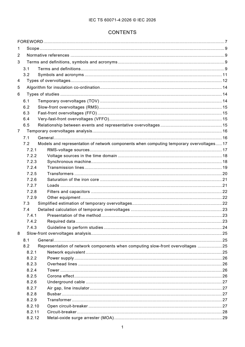
CONTENTS
FOREWORD . 7
1 Scope . 9
2 Normative references . 9
3 Terms and definitions, symbols and acronyms . 9
3.1 Terms and definitions . 9
3.2 Symbols and acronyms . 11
4 Types of overvoltages . 12
5 Algorithm for insulation co-ordination . 14
6 Types of studies . 14
6.1 Temporary overvoltages (TOV) . 14
6.2 Slow-front overvoltages (RMS) . 15
6.3 Fast-front overvoltages (FFO) . 15
6.4 Very-fast-front overvoltages (VFFO). 15
6.5 Relationship between events and representative overvoltages . 15
7 Temporary overvoltages analysis . 16
7.1 General . 16
7.2 Models and representation of network components when computing temporary overvoltages . 17
7.2.1 RMS-voltage sources . 17
7.2.2 Voltage sources in the time domain . 18
7.2.3 Synchronous machine. 18
7.2.4 Transmission lines . 19
7.2.5 Transformers . 20
7.2.6 Saturation of the iron core . 21
7.2.7 Loads . 21
7.2.8 Filters and capacitors . 22
7.2.9 Other equipment . 22
7.3 Simplified estimation of temporary overvoltages . 22
7.4 Detailed calculation of temporary overvoltages . 23
7.4.1 Presentation of the method . 23
7.4.2 Required data . 23
7.4.3 Guideline to perform studies . 24
8 Slow-front overvoltages analysis. 25
8.1 General . 25
8.2 Representation of network components when computing slow-front overvoltages . 25
8.2.1 Network equivalent . 25
8.2.2 Power supply . 26
8.2.3 Overhead lines . 26
8.2.4 Tower . 26
8.2.5 Corona effect . 26
8.2.6 Underground cable . 27
8.2.7 Air gap, line insulator . 27
8.2.8 Busbar . 27
8.2.9 Transformer . 27
8.2.10 Open circuit-breaker . 27
8.2.11 Circuit-breaker . 28
8.2.12 Metal-oxide surge arrester (MOA) . 29
8.2.13 Substation and tower earthing electrodes . 29
8.3 Fast methodology to conduct RMS studies . 30
8.4 Method to be employed . 30
8.5 Guideline to apply statistical methods . 30
8.5.1 Application of a full statistical method . 30
8.5.2 Semi-statistical method . 31
8.5.3 Modelling aspects . 31
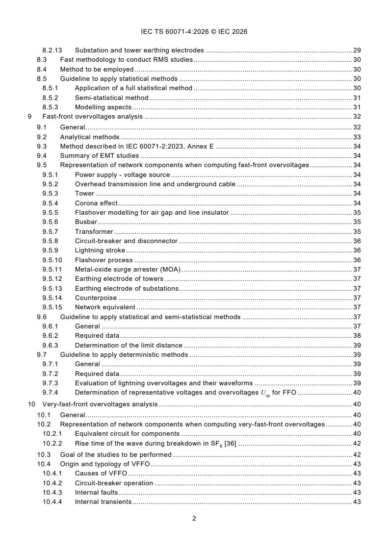
9 Fast-front overvoltages analysis . 32
9.1 General . 32
9.2 Analytical methods . 33
9.3 Method described in IEC 60071-2:2023, Annex E . 34
9.4 Summary of EMT studies . 34
9.5 Representation of network components when computing fast-front overvoltages . 34
9.5.1 Power supply - voltage source . 34
9.5.2 Overhead transmission line and underground cable . 34
9.5.3 Tower . 34
9.5.4 Corona effect . 34
9.5.5 Flashover modelling for air gap and line insulator . 35
9.5.6 Busbar . 35
9.5.7 Transformer . 35
9.5.8 Circuit-breaker and disconnector . 36
9.5.9 Lightning stroke . 36
9.5.10 Flashover process . 36
9.5.11 Metal-oxide surge arrester (MOA) . 37
9.5.12 Earthing electrode of towers . 37
9.5.13 Earthing electrode of substations . 37
9.5.14 Counterpoise . 37
9.5.15 Network equivalent . 37
9.6 Guideline to apply statistical and semi-statistical methods . 37
9.6.1 General . 37
9.6.2 Required data . 38
9.6.3 Determination of the limit distance . 39
9.7 Guideline to apply deterministic methods . 39
9.7.1 General . 39
9.7.2 Required data . 39
9.7.3 Evaluation of lightning overvoltages and their waveforms . 39
9.7.4 Determination of representative voltages and overvoltages U for FFO . 40
rp
10 Very-fast-front overvoltages analysis . 40
10.1 General . 40
10.2 Representation of network components when computing very-fast-front overvoltages . 40
10.2.1 Equivalent circuit for components . 40
10.2.2 Rise time of the wave during breakdown in SF [36] . 42
10.3 Goal of the studies to be performed . 42
10.4 Origin and typology of VFFO . 43
10.4.1 Causes of VFFO . 43
10.4.2 Circuit-breaker operation . 43
10.4.3 Internal faults. 43
10.4.4 Internal transients . 43
10.4.5 External transients . 43
10.5 Guideline to perform studies . 44
11 Test cases . 44
11.1 General . 44
11.2 Case 1-1: TOV on underground transmission lines (JEC-3408 [39]) . 44
11.2.1 General . 44
11.2.2 Description of the test circuit . 45
11.2.3 Results . 48
11.3 Case 1-2: TOV - Ferroresonances in isolated networks by switching of transformers . 48
11.3.1 General . 48
11.3.2 Input data and modelling . 49
11.3.3 Results . 50
11.4 Case 2-1: RMS - Energizing of a 400 kV-transmission line . 51
11.4.1 General . 51
11.4.2 Input data and modelling . 51
11.4.3 Method applied . 53
11.4.4 Results and interpretation . 54
11.4.5 Isolation co-ordination procedure . 55
11.5 Case 3-1: FFO at a transmission line-connected substation/power station caused
by lightning [30] . 56
11.5.1 General . 56
11.5.2 Description of the test circuit . 56
11.5.3 Results . 57
11.6 Case 3-2: FFO on an underground transmission line connected to a transmission line
caused by lightning [30] . 58
11.6.1 General . 58
11.6.2 Description of the test circuit . 59
11.6.3 Results . 60
11.7 Case 4-1: VFFO . 61
11.7.1 General . 61
11.7.2 Case 1: VFFO in a gas insulated substation (GIS) with U = 420 kV . 61
m
Annex A (informative) Outlines of the computational models for representing overhead lines and
underground cables . 67
Annex B (informative) Tower . 68
B.1 Lossless transmission line with constant parameters . 68
B.2 Lossless transmission line with inductance connected in parallel with damping resistance . 69
B.3 Inductive branch . 70
B.4 Cross-arm representation. 70
B.5 Propagation velocity. 70
Annex C (informative) Corona effect . 71
C.1 Suliciu model [57], [58] . 71
C.2 The linear corona model [59], [58] . 72
Annex D (informative) Flashover modelling . 74
D.1 Breakdown voltage-time (V-t) curve . 74
D.2 Air gap model based on the integration method [4] . 75
D.3 Air gap model based on the leader propagation model [4], [62] . 76
D.3.1 Discharge development process . 76
D.3.2 CIGRE model [4]. 77
D.3.3 Motoyama and Mozumi model [4], [64], [65], [66] . 78
Annex E (informative) Lightning stroke modelling . 79
E.1 Electrical model [4] . 79
E.2 Waveform . 79
E.3 Probabilistic distributions for the representation of the first negative downward strokes . 80
E.4 Probabilistic distributions for the representation of the negative downward
subsequent strokes . 82
E.5 Representation of the positive lightning strokes . 82
Annex F (informative) Earthing electrode of towers . 83
F.1 Simplified model . 83
F.2 Ionization model . 83
F.3 HF-model . 84
Annex G (informative) Application examples of statistical and semi-statistical methods. 85
G.1 Evaluation of the number of lightning strokes impacting the line, within the limit distance, per
year, and evaluation of the random distributions of peak current associated with these
lightning strokes . 85
G.1.1 Average attractive radius - strokes impacting the towers and the shield wires . 85
G.1.2 Attractive radius versus crest value of the stroke current: strokes impacting the towers
and the shield wires . 85
G.1.3 Direct application of an electro-geometric model . 86
G.2 Determination of the risk of failure for one configuration of the system [70] . 86
Bibliography . 88
Figure 1 – Types of overvoltages . 12
Figure 2 – Flow chart for the determination of rated or standard insulation level (defined in
IEC 60071-1:2019 [5], Figure 1) . 14
Figure 3 – RMS voltage source for unsymmetrical systems (three phase) . 17
Figure 4 – RMS voltage source for symmetrical systems (single phase) . 18
Figure 5 – Voltage source for synchronous machines (single phase) . 18
Figure 6 – Line element for representation (single phase) . 19
Figure 7 – π-section for representation (single phase) . 19
Figure 8 – Equivalent circuit of a transformer for RMS calculations (single phase) . 20
Figure 9 – Saturation curve of a 15,75 kV/10,5 kV transformer. 21
Figure 10 – Representation of load . 22
Figure 11 – Representation of the synchronous machine . 26
Figure 12 – Diagram showing double distribution used for statistical switches . 29
Figure 13 – Network representation - Examples a) and b) . 32
Figure 14 – Simplified model of earthing electrode . 37
Figure 15 – Application of statistical or semi-statistical methods . 38
Figure 16 – Calculation model for lightning overvoltage evaluation . 39
Figure 17 – At the GIS-air interface: coupling between enclosure and earth (Z ), between overhead
line and earth (Z ) and between bus conductor and enclosure (Z ) [36] . 44
2 1
Figure 18 – Single-line circuit for underground transmission lines . 45
Figure 19 – Diagram for control circuits for generator . 47
Figure 20 – An example of the calculated results of TOV on 500 kV underground transmission lines . 48
Figure 21 – Simplified equivalent circuit of the simulated subnetwork . 49
Figure 22 – U(ψ)/I-characteristics of investigated voltage transformers VT . 49
Figure 23 – Phase-to-earth voltages at ferroresonances in 110 kV subnetwork with a phase-to-earth
capacitance C = 2 nF (mean value) . 50
E
Figure 24 – Simulated RMS values of phase-to-earth voltages u (t) for voltage transformers A, B and C . 50
pe
Figure 25 – Simplified equivalent circuit of the simulated network section . 51
Figure 26 – Geometry of the overhead line tower . 52
Figure 27 – Investigated scenarios of line energization . 53
Figure 28 – Phase-to-earth and phase-to-phase voltages in scenario I at node SA1 . 54
Figure 29 – Histogram and cumulative frequency of phase-to-earth overvoltage factors in scenario I
(Example) . 54
Figure 30 – Calculated and derived cumulative frequencies of overvoltages in scenario I at node SA2 . 55
Figure 31 – Circuit for a transmission line-connected substation/power station . 56
Figure 32 – An example of calculated results of FFO on substation . 58
Figure 33 – Circuit for an underground transmission line connected to a transmission line [30] . 58
Figure 34 – Circuit of a vertical down-conductor. 59
Figure 35 – Circuit for an underground transmission line [30] . 60
Figure 36 – Examples of the V-L curves on underground transmission lines [30] . 61
Figure 37 – Exemplary GIS under investigation . 62
Figure 38 – Investigated busbar switching operation . 63
Figure 39 – Voltage at point "A" of the energized busbar (marked red in Figure 38) . 64
Figure 40 – Voltage at the busbar and the transformer at the sending end . 64
Figure 41 – Voltage at the busbar and the transformer at the sending end . 65
Figure 42 – Comparison between the voltage curves at point "A" at the energized busbar if all gas
insulated parts are modelled as distributed lines (black) or as π-sections (red) . 65
Figure 43 – Comparison between the voltage curves at point "A" at the energized busbar with
(red) and without (black) a negative trapped charge of 1 p.u. . 66
Figure B.1 – Multi-story transmission tower . 69
Figure C.1 – The linear corona model . 72
Figure D.1 – V-t curve for the standard lightning impulse voltage waveform . 74
Figure D.2 – Schematic representation of the integration method [4] . 75
Figure D.3 – Overview of the discharge development process [4] . 76
Figure E.1 – Equivalent circuit of lightning stroke [4] . 79
Figure E.2 – Double ramp waveform . 79
Figure E.3 – CIGRE concave waveform . 80
Figure F.1 – Simplified model of earthing electrode . 83
Figure G.1 – Application of the electro-geometric model . 86
Figure G.2 – Limit function for the two random variables considered: the maximum value of
the lightning current and the disruptive voltage . 87
Table 1 – Classes and waveforms of overvoltages - Standard voltage waveforms and standard
withstand tests (taken from IEC 60071-1:2019 [5]) . 13
Table 2 – Relationship between events and representative overvoltages . 16
Table 3 – Typical overvoltage factors for temporary overvoltages . 22
Table 4 – Types of approaches to perform FFO studies . 33
Table 5 – Minimum earth capacitance for transformers . 35
Table 6 – Typical earth capacitance for various types of transformers . 36
Table 7 – Typical earth capacitance for circuit-breakers and disconnectors . 36
Table 8 – Representation of components in VFFO studies . 41
Table 9 – Overview of the test circuit . 45
Table 10 – Circuit constants of generator . 46
Table 11 – Characteristics of magnetic saturation for step-up transformer . 47
Table 12 – Characteristics of voltage-current characteristics of the surge arresters . 48
Table 13 – Capacitances for the investigated configuration . 50
Table 14 – Short-circuit parameters . 51
Table 15 – Electrical overhead line parameters . 52
Table 16 – Characteristics of the surge arresters . 52
Table 17 – Minimum and maximum time delay between closing of breaker poles . 53
Table 18 – System configurations . 53
Table 19 – Recorded overvoltages . 54
Table 20 – Overvoltage factors . 55
Table 21 – The waveform parameters of ideal current source I(t) . 56
Table 22 – The line constants of dead-end tower . 57
Table 23 – The waveform parameters of ideal current source I(t) [30] . 59
Table 24 – Electric characteristics of gas insulated parts . 62
Table A.1 – Guideline for computational models representing the overhead lines
and underground cables . 67
Table D.1 – Values of U , k, DE for different configurations proposed by reference [63] . 76
Table D.2 – Constants for CIGRE model . 77
Table D.3 – Constants for Motoyama and Mozumi model . 78
Table E.1 – Representation of the first negative downward strokes . 81
Table E.2 – Time to half-value of the first negative downward strokes . 81
Table E.3 – Representation of the negative downward subsequent strokes . 82
Table E.4 – Time to half-value of negative downward subsequent strokes . 82
INTERNATIONAL ELECTROTECHNICAL COMMISSION
____________
Instructions for simulation-based insulation coordination and modelling of
electrical networks
FOREWORD
1) The International Electrotechnical Commission (IEC) is a worldwide organization for standardization comprising all national
electrotechnical committees (IEC National Committees). The object of IEC is to promote international co-operation on all
questions concerning standardization in the electrical and electronic fields. To this end and in addition to other activities, IEC
publishes International Standards, Technical Specifications, Technical Reports, Publicly Available Specifications (PAS) and
Guides (hereafter referred to as "IEC Publication(s)"). Their preparation is entrusted to technical committees; any IEC National
Committee interested in the subject dealt with may participate in this preparatory work. International, governmental and non-
governmental organizations liaising with the IEC also participate in this preparation. IEC collaborates closely with the
International Organization for Standardization (ISO) in accordance with conditions determined by agreement between the two
organizations.
2) The formal decisions or agreements of IEC on technical matters express, as nearly as possible, an international consensus of
opinion on the relevant subjects since each technical committee has representation from all interested IEC National Committees.
3) IEC Publications have the form of recommendations for international use and are accepted by IEC National Committees in that
sense. While all reasonable efforts are made to ensure that the technical content of IEC Publications is accurate, IEC cannot
be held responsible for the way in which they are used or for any misinterpretation by any end user.
4) In order to promote international uniformity, IEC National Committees undertake to apply IEC Publications transparently to the
maximum extent possible in their national and regional publications. Any divergence between any IEC Publication and the
corresponding national or regional publication shall be clearly indicated in the latter.
5) IEC itself does not provide any attestation of conformity. Independent certification bodies provide conformity assessment
services and, in some areas, access to IEC marks of conformity. IEC is not responsible for any services carried out by
independent certification bodies.
6) All users should ensure that they have the latest edition of this publication.
7) No liability shall attach to IEC or its directors, employees, servants or agents including individual experts and members of its
technical committees and IEC National Committees for any personal injury, property damage or other damage of any nature
whatsoever, whether direct or indirect, or for costs (including legal fees) and expenses arising out of the publication, use of, or
reliance upon, this IEC Publication or any other IEC Publications.
8) Attention is drawn to the Normative references cited in this publication. Use of the referenced publications is indispensable for
the correct application of this publication.
9) IEC draws attention to the possibility that the implementation of this document may involve the use of (a) patent(s). IEC takes
no position concerning the evidence, validity or applicability of any claimed patent rights in respect thereof. As of the date of
publication of this document, IEC had not received notice of (a) patent(s), which may be required to implement this document.
However, implementers are cautioned that this may not represent the latest information, which may be obtained from the patent
database available at https://patents.iec.ch. IEC shall not be held responsible for identifying any or all such patent rights.
IEC TS 60071-4 has been prepared by IEC technical committee 99: Insulation co-ordination and system
engineering of high voltage electrical power installations above 1,0 kV AC and 1,5 kV DC. It is a Technical
Specification.
This edition cancels and replaces IEC TR 60071-4, published in 2004. This edition constitutes a technical
revision
The text of this Technical Specification is based on the following documents:
Draft Report on voting
99/535/DTS 99/548/RVDTS
Full information on the voting for its approval can be found in the report on voting indicated in the above
table.
The language used for the development of this Technical Specification is English.
This document was drafted in accordance with ISO/IEC Directives, Part 2, and developed in accordance
with ISO/IEC Directives, Part 1 and ISO/IEC Directives, IEC Supplement, available at
www.iec.ch/members_experts/refdocs. The main document types developed by IEC are described in
greater detail at www.iec.ch/publications.
A list of all parts in the IEC 60071 series, published under the general title Insulation co-ordination, can be
found on the IEC website.
The committee has decided that the contents of this document will remain unchanged until the stability date
indicated on the IEC website under webstore.iec.ch in the data related to the specific document. At this
date, the document will be
– reconfirmed,
– withdrawn, or
– revised.
1 Scope
This technical specification gives guidance on conducting insulation co-ordination studies which propose
internationally recognized recommendations:
– for the computational modelling of electrical systems, and
– for the implementation of deterministic and probabilistic methods adapted to the use of numerical
programmes.
Its object is to give information in terms of methods, modelling and examples that support the application
of the approaches presented in IEC 60071-2:2023, and for the selection of insulation levels of equipment
or installations, as defined in IEC 60071-1:2019.
2 Normative references
The following documents are referred to in the text in such a way that some or all of their content constitutes
requirements of this document. For dated references, only the edition cited applies. For undated references,
the latest edition of the referenced document (including any amendments) applies.
IEC 60060-1:2025, High-voltage test techniques - Part 1: General terminology and test requirements
IEC 60071-1:2019, Insulation co-ordination - Part 1: Definitions, principles and rules
IEC 60071-2:2023, Insulation co-ordination - Part 2: Application guidelines
IEC 60071-11:2022, Insulation co-ordination - Part 11:Definitions, principles and rules for HVDC system
IEC 60071-12:2022, Insulation co-ordination - Part 12: Application guidelines for LCC HVDC converter
stations
IEC 60099-4:2014, Surge arresters - Part 4: Metal-oxide surge arresters without gaps for a.c. systems
IEC 62271-100:2021, High-voltage switchgear and controlgear - Part 100: Alternating-current circuit-
breakers
3 Terms and definitions, symbols and acronyms
For the purposes of this document, the terms and definitions given in IEC 60071-1:2019 and the following
apply.
ISO and IEC maintain terminology databases for use in standardization at the following addresses:
– IEC Electropedia: available at https://www.electropedia.org/
– ISO Online browsing platform: available at https://www.iso.org/obp
NOTE Certain references are taken from the IEC Electrotechnical Vocabulary (https://www.electropedia.org).
3.1 Terms and definitions
3.1.1
b
...