

IEC TS 62332-1:2026
(Main)Electrical insulation systems (EIS) - Thermal evaluation of combined liquid and solid components - Part 1: General requirements
- Abstract
IEC TS 62332-1:2026 specifies a dual-temperature test procedure for the thermal evaluation and qualification of electrical insulation systems (EISs). This document is applicable to EISs containing solid and liquid components where the thermal ageing factor is dominant, without restriction to voltage class. This third edition cancels and replaces the second edition published in 2011. This edition constitutes a technical revision.
This edition includes the following significant technical changes with respect to the previous edition:
- Modifications have been made based on an extensive test series conducted using this methodology based on the first edition. This included updating expected times and temperatures to use in order to get useful results, as well as making the range of equipment covered more broad. The method now covers electrotechnical devices using different sealing systems, as well as devices using enamel covered wires.
- Status
- Published
- Publication Date
- 25-May-2026
- Current Stage
- PPUB - Publication issued
- Start Date
- 26-May-2026
- Completion Date
- 05-Jun-2026
Buy Documents
IEC TS 62332-1:2026 - Electrical insulation systems (EIS) - Thermal evaluation of combined liquid and solid components - Part 1: General requirements
REDLINE IEC TS 62332-1:2026 RLV - Electrical insulation systems (EIS) - Thermal evaluation of combined liquid and solid components - Part 1: General requirements
IEC TS 62332-1:2026 is an IEC Technical Specification for the thermal evaluation and qualification of electrical insulation systems (EIS) with combined solid and liquid components. It specifies a dual-temperature accelerated ageing test procedure for EISs where thermal ageing is the dominant factor, without restriction to voltage class.
The document is aimed at people who need to compare a candidate EIS with a reference EIS under controlled ageing conditions. In practice, that includes equipment developers, test laboratories, and product technical committees working on liquid-immersed electrotechnical products.
What does IEC TS 62332-1:2026 specify?
IEC TS 62332-1:2026 specifies the general requirements for a dual-temperature test method, including the test apparatus, test object construction, ageing procedure, diagnostic testing, and data analysis. It is the general part of the IEC 62332 series, and its later parts are intended to cover product-specific test requirements.
The document is organized into Clauses 1 to 7 and one informative annex:
| Part | What it covers |
|---|---|
| Clause 1 | Scope |
| Clause 2 | Normative references |
| Clause 3 | Terms and definitions |
| Clause 4 | Thermal ageing test apparatus |
| Clause 5 | Construction of the test object |
| Clause 6 | Test procedures |
| Clause 7 | Analysis of data and report |
| Annex A | Informative component volume ratio spreadsheet example |
What are the key requirements of IEC TS 62332-1:2026?
IEC TS 62332-1:2026 is built around comparative ageing of a reference EIS and a candidate EIS. The method uses separate control of the solid and liquid temperatures in the same ageing cell, then compares how the two systems reach end-of-life under the same diagnostic approach.
Thermal ageing apparatus
Clause 4 requires an ageing system that can age solid and liquid components separately. The apparatus includes ageing cells, power supply, control system, safety system, sampling system, and monitoring or data collection.
The ageing cell must allow for liquid expansion, liquid sampling, electrical pass-throughs, immersion heaters, control and monitoring elements, gas blanketing, and pressure relief. The control feedback circuit must keep each temperature within ±2 K. In practice, that means the test is only valid if the solid and liquid temperature histories are kept stable and recorded.
A gas blanketing system is required to simulate the product under evaluation, such as sealed nitrogen or a desiccated-air type arrangement. Each cell also needs pressure relief and independent over-temperature protection for both liquid and solid temperature sensors.
Test object construction
Clause 5 requires the test object to represent the EIS portion of the electrotechnical product being modelled. The component volumes in the test object have to reflect the product being simulated, and Annex A gives a spreadsheet example for calculating these ratios.
The usual test object includes a current-carrying conductor, conductor insulation, insulation spacers or barriers, and a liquid. The liquid volume is determined at 20 °C. The document also allows representative additional components that affect the EIS, such as core steel or enclosure material, if they are relevant to the product being modelled.
Preparation and ageing procedure
Clause 6 requires drying of solid and liquid samples before test start, followed by vacuum impregnation of the conductor assembly and other materials with the liquid under evaluation. The impregnation is carried out for between six and 24 hours at 70 °C to 90 °C.
The reference EIS used to validate the method is cellulose solid insulation with mineral oil unless the product technical committee selects another established reference system. For the reference system, the document states an ATE of 105 °C, and Table 1 gives the ageing temperatures used for the solid and liquid components.
For the candidate EIS, at least three ageing temperatures are used, and there must be at least three ageing cells at each temperature. The document also describes a sampling pattern that increases the amount of end-point data, so the later ageing periods are better populated than the early ones.
Diagnostic tests and end-point criteria
Clause 6 requires diagnostic tests on both solid and liquid samples before ageing starts and after each ageing cell is shut down. Tables 2 and 3 list typical tests for cellulosic materials and liquids, such as moisture content, dielectric strength, tensile strength, breakdown voltage, acidity, water content, and dissolved gas.
For enamel covered wires, the document notes that most solid-material tests are not appropriate and that dielectric strength retention is the key characteristic to monitor. That matters because the method can be adapted to different insulation constructions, but the diagnostic test has to fit the material.
Clause 7 requires the end-point criterion to be defined before the test starts. For solid insulation, the preferred end-point criterion is 50 % of the original mechanical property, or 25 % of the original degree of polymerization for paper. For liquids, the end-point criterion is selected by the product technical committee, and mineral oil uses the values in IEC 60422.
The life at each ageing temperature is calculated from the solid-component results in accordance with IEC 60216-3, and the regression analysis follows IEC 60216-5. The report must include the test objects, ageing conditions, diagnostic tests, end-point criteria, times to end-of-life, and the regression results used to derive ATE or RTE.
What terms does IEC TS 62332-1:2026 define?
- Electrical insulation system (EIS) - An insulating structure made up of one or more insulating materials and the associated conducting parts used in an electrotechnical device.
- Candidate EIS - The EIS being evaluated for service capability under thermal stress.
- Reference EIS - An established EIS with known service experience or known comparative functional evaluation.
- Thermal class - The numerical temperature designation for an EIS, linked to IEC 60085.
- Assigned thermal endurance (ATE) - The temperature value assigned to the reference EIS from known service or comparative evaluation.
- Relative thermal endurance (RTE) - The temperature value for the candidate EIS relative to the ATE of the reference EIS under the same ageing and diagnostic procedure.
- Ageing cell - A sealed container holding the liquid, test object, heaters, and thermocouples for control and monitoring.
- End-point criterion - The selected property value, or change in property, that defines end-of-life.
Who uses IEC TS 62332-1:2026?
IEC TS 62332-1:2026 is used by technical committees, testing laboratories, and engineers working on electrotechnical products with liquid and solid insulation. It is especially relevant for products such as power transformers and other liquid-immersed equipment where the solid insulation near active parts ages differently from the bulk liquid.
Quality teams and buyers may use it to check whether a supplier’s thermal evaluation method is based on a recognized comparative test, and to understand what data should appear in a test report. It is also relevant where different sealing systems or enamel covered wires are part of the insulation design.
What changed in IEC TS 62332-1:2026 from the previous edition?
IEC TS 62332-1:2026 is the third edition, and it cancels and replaces the second edition published in 2011. The document states that this edition is a technical revision.
The main technical changes stated in the document are:
- adjustments based on a large test series carried out with this methodology
- updated expected times and temperatures to obtain useful results
- a broader range of equipment covered
- coverage of electrotechnical devices using different sealing systems
- coverage of devices using enamel covered wires
Which standards are used with IEC TS 62332-1:2026?
- IEC 60216-3 - gives the calculation method for thermal endurance characteristics and life at temperature.
- IEC 60216-5 - gives the method for determining relative thermal endurance index and the regression analysis approach.
- IEC 60296 - specifies unused mineral insulating oils for transformers and switchgear, which are used in the reference system.
- IEC 60422 - gives supervision and maintenance guidance for mineral insulating oils, and is used for liquid conditioning and liquid end-point criteria.
- IEC 60505 - provides the overall framework for evaluation and qualification of EIS and is used for interpretation.
- IEC 60085:2007 - is used for thermal class designation in the ageing temperature table.
What does the IEC TS 62332-1:2026 document contain?
The document contains the full test framework needed to run a comparative thermal evaluation program for a liquid-and-solid EIS. It includes apparatus design requirements, sample preparation, test object construction, diagnostic testing, ageing temperatures and periods, and the analysis needed to derive end-of-life and thermal rating data.
It also includes Figure 1 for the ageing cell cross-section and Figure 2 for an example insulation package for a transformer winding. Tables 2 and 3 list typical diagnostic tests, Table 4 links expected thermal class to ageing temperatures and periods, and Annex A gives a worked example of component volume ratio calculations for an ageing-cell model.
Relations
- Effective Date
- 08-Mar-2024
Buy Documents
IEC TS 62332-1:2026 - Electrical insulation systems (EIS) - Thermal evaluation of combined liquid and solid components - Part 1: General requirements
REDLINE IEC TS 62332-1:2026 RLV - Electrical insulation systems (EIS) - Thermal evaluation of combined liquid and solid components - Part 1: General requirements
Get Certified
Connect with accredited certification bodies for this standard

IMQ S.p.A. (Certification)
Italian electrical product certification.

SLG Prüf- und Zertifizierungs GmbH
German testing and certification body.

UL Solutions
Global safety science company with testing, inspection and certification.
Sponsored listings
Frequently Asked Questions
IEC TS 62332-1:2026 is a technical specification published by the International Electrotechnical Commission (IEC). Its full title is "Electrical insulation systems (EIS) - Thermal evaluation of combined liquid and solid components - Part 1: General requirements". This standard covers: IEC TS 62332-1:2026 specifies a dual-temperature test procedure for the thermal evaluation and qualification of electrical insulation systems (EISs). This document is applicable to EISs containing solid and liquid components where the thermal ageing factor is dominant, without restriction to voltage class. This third edition cancels and replaces the second edition published in 2011. This edition constitutes a technical revision. This edition includes the following significant technical changes with respect to the previous edition: - Modifications have been made based on an extensive test series conducted using this methodology based on the first edition. This included updating expected times and temperatures to use in order to get useful results, as well as making the range of equipment covered more broad. The method now covers electrotechnical devices using different sealing systems, as well as devices using enamel covered wires.
IEC TS 62332-1:2026 specifies a dual-temperature test procedure for the thermal evaluation and qualification of electrical insulation systems (EISs). This document is applicable to EISs containing solid and liquid components where the thermal ageing factor is dominant, without restriction to voltage class. This third edition cancels and replaces the second edition published in 2011. This edition constitutes a technical revision. This edition includes the following significant technical changes with respect to the previous edition: - Modifications have been made based on an extensive test series conducted using this methodology based on the first edition. This included updating expected times and temperatures to use in order to get useful results, as well as making the range of equipment covered more broad. The method now covers electrotechnical devices using different sealing systems, as well as devices using enamel covered wires.
IEC TS 62332-1:2026 is classified under the following ICS (International Classification for Standards) categories: 29.080.30 - Insulation systems. The ICS classification helps identify the subject area and facilitates finding related standards.
IEC TS 62332-1:2026 has the following relationships with other standards: It is inter standard links to IEC TS 62332-1:2011. Understanding these relationships helps ensure you are using the most current and applicable version of the standard.
IEC TS 62332-1:2026 is available in PDF format for immediate download after purchase. The document can be added to your cart and obtained through the secure checkout process. Digital delivery ensures instant access to the complete standard document.
Standards Content (Sample)
IEC TS 62332-1 ®
Edition 3.0 2026-05
TECHNICAL
SPECIFICATION
Electrical insulation systems (EIS) - Thermal evaluation of combined liquid and
solid components -
Part 1: General requirements
ICS 29.080.30 ISBN 978-2-8327-1242-9
All rights reserved. Unless otherwise specified, no part of this publication may be reproduced or utilized in any form or
by any means, electronic or mechanical, including photocopying and microfilm, without permission in writing from either
IEC or IEC's member National Committee in the country of the requester. If you have any questions about IEC copyright
or have an enquiry about obtaining additional rights to this publication, please contact the address below or your local
IEC member National Committee for further information.
IEC Secretariat Tel.: +41 22 919 02 11
3, rue de Varembé info@iec.ch
CH-1211 Geneva 20 www.iec.ch
Switzerland
About the IEC
The International Electrotechnical Commission (IEC) is the leading global organization that prepares and publishes
International Standards for all electrical, electronic and related technologies.
About IEC publications
The technical content of IEC publications is kept under constant review by the IEC. Please make sure that you have the
latest edition, a corrigendum or an amendment might have been published.
IEC publications search - IEC Products & Services Portal - products.iec.ch
webstore.iec.ch/advsearchform Discover our powerful search engine and read freely all the
The advanced search enables to find IEC publications by a publications previews, graphical symbols and the glossary.
variety of criteria (reference number, text, technical With a subscription you will always have access to up to date
committee, …). It also gives information on projects, content tailored to your needs.
replaced and withdrawn publications.
Electropedia - www.electropedia.org
The world's leading online dictionary on electrotechnology,
IEC Just Published - webstore.iec.ch/justpublished
Stay up to date on all new IEC publications. Just Published containing more than 22 500 terminological entries in English
details all new publications released. Available online and and French, with equivalent terms in 25 additional languages.
once a month by email. Also known as the International Electrotechnical Vocabulary
(IEV) online.
IEC Customer Service Centre - webstore.iec.ch/csc
If you wish to give us your feedback on this publication or
need further assistance, please contact the Customer
Service Centre: sales@iec.ch.
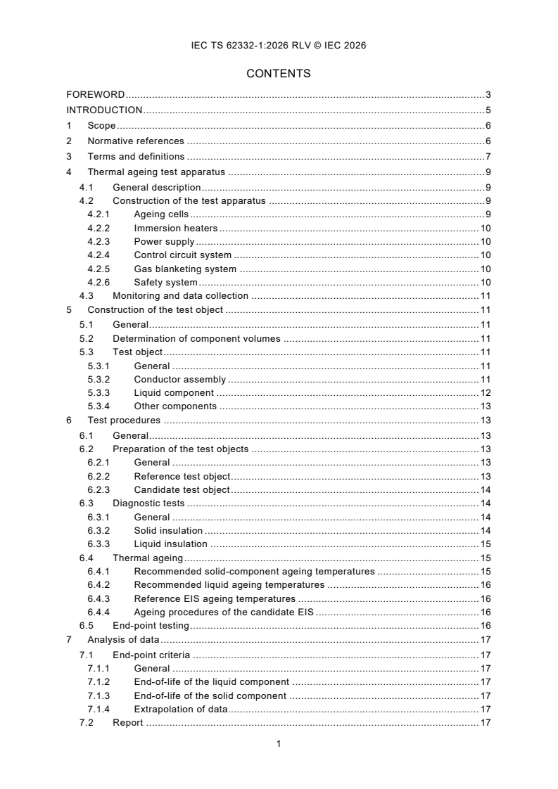
CONTENTS
FOREWORD . 3
INTRODUCTION . 5
1 Scope . 6
2 Normative references . 6
3 Terms and definitions . 6
4 Thermal ageing test apparatus . 8
4.1 General description . 8
4.2 Construction of the test apparatus . 8
4.2.1 Ageing cells . 8
4.2.2 Immersion heaters . 9
4.2.3 Power supply . 9
4.2.4 Control circuit system . 9
4.2.5 Gas blanketing system . 9
4.2.6 Safety system . 9
4.3 Monitoring and data collection . 10
5 Construction of the test object . 10
5.1 General . 10
5.2 Determination of component volumes . 10
5.3 Test object . 10
5.3.1 General . 10
5.3.2 Conductor assembly . 10
5.3.3 Liquid component . 11
5.3.4 Other components . 12
6 Test procedures . 12
6.1 General . 12
6.2 Preparation of the test objects . 12
6.2.1 General . 12
6.2.2 Reference test object . 12
6.2.3 Candidate test object . 13
6.3 Diagnostic tests . 13
6.3.1 General . 13
6.3.2 Solid insulation . 13
6.3.3 Liquid insulation . 14
6.4 Thermal ageing . 14
6.4.1 Recommended solid-component ageing temperatures . 14
6.4.2 Recommended liquid ageing temperatures . 15
6.4.3 Reference EIS ageing temperatures . 15
6.4.4 Ageing procedures of the candidate EIS . 15
6.5 End-point testing . 15
7 Analysis of data . 16
7.1 End-point criteria . 16
7.1.1 General . 16
7.1.2 End-of-life of the liquid component . 16
7.1.3 End-of-life of the solid component . 16
7.1.4 Extrapolation of data. 16
7.2 Report . 16
Annex A (informative) Component volume ratio spreadsheet example . 18
Bibliography . 19
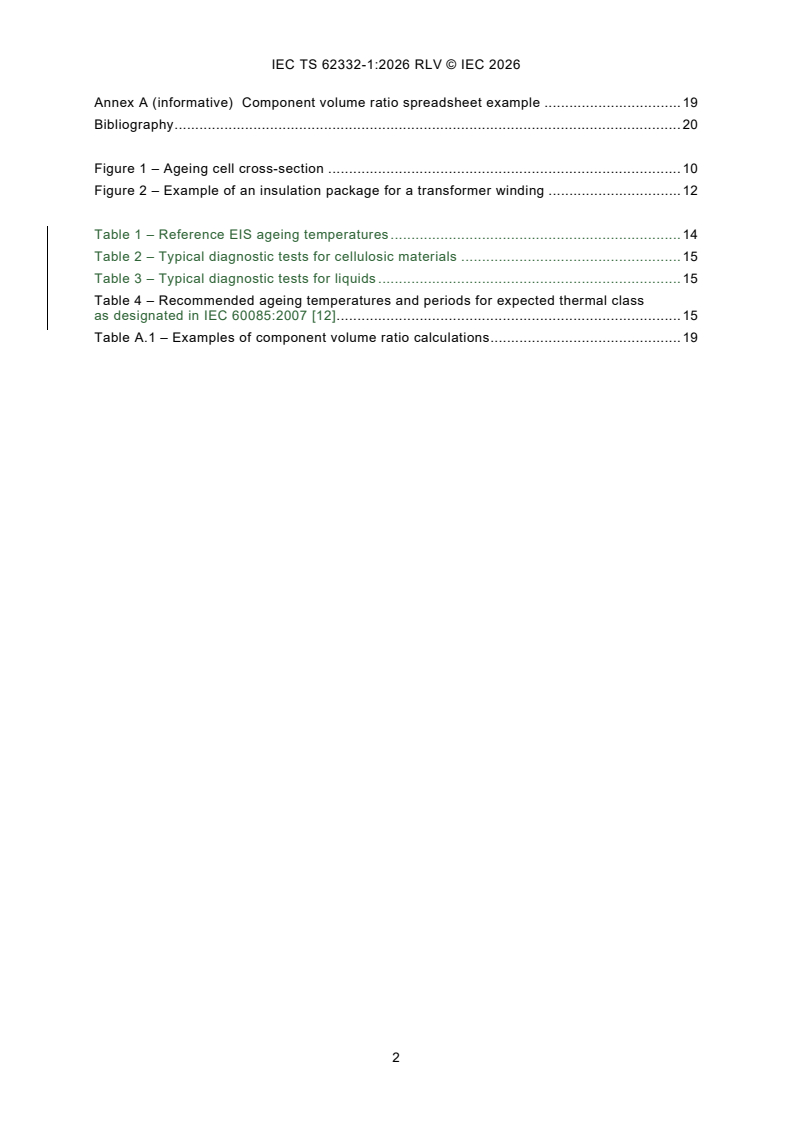
Figure 1 – Ageing cell cross-section . 9
Figure 2 – Example of an insulation package for a transformer winding . 11
Table 1 – Reference EIS ageing temperatures . 13
Table 2 – Typical diagnostic tests for cellulosic materials . 14
Table 3 – Typical diagnostic tests for liquids . 14
Table 4 – Recommended ageing temperatures and periods for expected thermal class
as designated in IEC 60085:2007 [12] . 14
Table A.1 – Examples of component volume ratio calculations . 18
INTERNATIONAL ELECTROTECHNICAL COMMISSION
____________
Electrical insulation systems (EIS) - Thermal evaluation of combined
liquid and solid components -
Part 1: General requirements
FOREWORD
1) The International Electrotechnical Commission (IEC) is a worldwide organization for standardization comprising
all national electrotechnical committees (IEC National Committees). The object of IEC is to promote international
co-operation on all questions concerning standardization in the electrical and electronic fields. To this end and
in addition to other activities, IEC publishes International Standards, Technical Specifications, Technical Reports,
Publicly Available Specifications (PAS) and Guides (hereafter referred to as “IEC Publication(s)”). Their
preparation is entrusted to technical committees; any IEC National Committee interested in the subject dealt with
may participate in this preparatory work. International, governmental and non-governmental organizations liaising
with the IEC also participate in this preparation. IEC collaborates closely with the International Organization for
Standardization (ISO) in accordance with conditions determined by agreement between the two organizations.
2) The formal decisions or agreements of IEC on technical matters express, as nearly as possible, an international
consensus of opinion on the relevant subjects since each technical committee has representation from all
interested IEC National Committees.
3) IEC Publications have the form of recommendations for international use and are accepted by IEC National
Committees in that sense. While all reasonable efforts are made to ensure that the technical content of IEC
Publications is accurate, IEC cannot be held responsible for the way in which they are used or for any
misinterpretation by any end user.
4) In order to promote international uniformity, IEC National Committees undertake to apply IEC Publications
transparently to the maximum extent possible in their national and regional publications. Any divergence between
any IEC Publication and the corresponding national or regional publication shall be clearly indicated in the latter.
5) IEC itself does not provide any attestation of conformity. Independent certification bodies provide conformity
assessment services and, in some areas, access to IEC marks of conformity. IEC is not responsible for any
services carried out by independent certification bodies.
6) All users should ensure that they have the latest edition of this publication.
7) No liability shall attach to IEC or its directors, employees, servants or agents including individual experts and
members of its technical committees and IEC National Committees for any personal injury, property damage or
other damage of any nature whatsoever, whether direct or indirect, or for costs (including legal fees) and
expenses arising out of the publication, use of, or reliance upon, this IEC Publication or any other IEC
Publications.
8) Attention is drawn to the Normative references cited in this publication. Use of the referenced publications is
indispensable for the correct application of this publication.
9) IEC draws attention to the possibility that the implementation of this document may involve the use of (a) patent(s).
IEC takes no position concerning the evidence, validity or applicability of any claimed patent rights in respect
thereof. As of the date of publication of this document, IEC had not received notice of (a) patent(s), which may
be required to implement this document. However, implementers are cautioned that this may not represent the
latest information, which may be obtained from the patent database available at https://patents.iec.ch. IEC shall
not be held responsible for identifying any or all such patent rights.
IEC TS 62332-1 has been prepared by IEC technical committee 112: Evaluation and
qualification of electrical insulating materials and systems. It is a Technical Specification.
This third edition cancels and replaces the second edition published in 2011. This edition
constitutes a technical revision.
This edition includes the following significant technical changes with respect to the previous
edition:
a) Modifications have been made based on an extensive test series conducted using this
methodology based on the first edition. This included updating expected times and
temperatures to use in order to get useful results, as well as making the range of equipment
covered more broad. The method now covers electrotechnical devices using different
sealing systems, as well as devices using enamel covered wires.
The text of this Technical Specification is based on the following documents:
Draft Report on voting
112/716/DTS 112/723/RVDTS
Full information on the voting for its approval can be found in the report on voting indicated in
the above table.
The language used for the development of this Technical Specification is English.
This document was drafted in accordance with ISO/IEC Directives, Part 2, and developed in
accordance with ISO/IEC Directives, Part 1 and ISO/IEC Directives, IEC Supplement, available
at www.iec.ch/members_experts/refdocs. The main document types developed by IEC are
described in greater detail at www.iec.ch/publications.
A list of all parts in the IEC 62332 series, published under the general title Electrical insulation
systems (EIS) -Thermal evaluation of combined liquid and solid components, can be found on
the IEC website.
The committee has decided that the contents of this document will remain unchanged until the
stability date indicated on the IEC website under webstore.iec.ch in the data related to the
specific document. At this date, the document will be
– reconfirmed,
– withdrawn, or
– revised.
INTRODUCTION
This document specifies a method for the thermal evaluation of electrical insulation systems
(EISs) for electrotechnical products with combined liquid and solid components. This document
covers general test requirements. It is intended that subsequent parts will cover specific product
test requirements.
Prior to this document, the procedure for determining the thermal endurance of insulation
systems for liquid-immersed products involved one of two processes: firstly, sealed-tube ageing
and, secondly, ageing of full-scale models.
The ageing of full-scale models is impractical, especially for larger products, such as power
transformers. Similarly, the use of sealed-tube ageing is not practical when testing components
having drastically different thermal capabilities. For example, testing of a system with a solid
material with an RTI of 200 °C with a liquid having a 130 °C thermal capability cannot be
performed efficiently. Accelerated ageing temperatures which significantly age the liquid will
result in extremely long ageing times for the solid. Accelerated ageing temperatures which
significantly age the solid will result in extreme, or even hazardous, ageing of the liquid.
This document specifies an accelerated thermal ageing procedure and model that allows for
the solid materials to be aged at temperatures separate from the liquid ageing temperatures,
all in the same apparatus. The model acts more in the true-life ageing mode of insulation
systems, where solid insulation near the active parts is exposed to much higher temperatures
than the major volume of liquid in the equipment. The model contains all the primary EIS
elements, and in relative component ratios which compare with actual electrotechnical products.
The model has a dual temperature capability that allows independent control of the
temperatures of the solid and liquid components by the use of separate circuits. A detailed
bibliography is provided.
Further useful information can be found in IEC 60076-6 [1], IEC 60076-7 [2], IEC 60076-14 [3],
IEC 60641-2 [4], [5], [6], [7] and[8].
1 Scope
This document specifies a dual-temperature test procedure for the thermal evaluation and
qualification of electrical insulation systems (EISs).
This document is applicable to EISs containing solid and liquid components where the thermal
ageing factor is dominant, without restriction to voltage class.
2 Normative references
The following documents are referred to in the text in such a way that some or all of their content
constitutes requirements of this document. For dated references, only the edition cited applies.
For undated references, the latest edition of the referenced document (including any
amendments) applies.
IEC 60216-3, Electrical insulating materials - Thermal endurance properties - Part 3:
Instructions for calculating thermal endurance characteristics
IEC 60216-5, Electrical insulating materials - Thermal endurance properties - Part 5:
Determination of relative thermal endurance index (RTE) of an insulating material
IEC 60296, Fluids for electrotechnical applications - Unused mineral insulating oils for
transformers and switchgear
IEC 60422, Mineral insulating oils in electrical equipment - Supervision and maintenance
guidance
IEC 60505, Evaluation and qualification of electrical insulation systems
3 Terms and definitions
For the purposes of this document, the terms and definitions given in IEC 60505 and the
following apply.
ISO and IEC maintain terminology databases for use in standardization at the following
addresses:
– IEC Electropedia: available at https://www.electropedia.org/
– ISO Online browsing platform: available at https://www.iso.org/obp
3.1
electrical insulation system
EIS
insulating structure containing one or more electrical insulating materials (EIMs) together with
associated conducting parts employed in an electrotechnical device
Note 1 to entry: EIMs with different temperature indices (temperature index (TI), temperature index by analytical
test (TIA) or relative thermal index (RTI)) as specified in IEC 60216-5 [10]) can be combined to form an EIS, which
has a thermal class (3.4) that can be higher or lower than that of any of the individual components as specified in
IEC 60505 [11].
[SOURCE: IEC 60505:2011 [9], 3.1.1, modified – Note 1 to entry has been added.]
3.2
candidate EIS
EIS (3.1) under evaluation to determine its service capability with regard to thermal stresses
3.3
reference EIS
evaluated and established EIS (3.1) with either a known service experience record or a known
comparative functional evaluation as a basis
3.4
thermal class
designation of an EIS (3.1) that is equal to the numerical value of the maximum temperature in
degrees Celsius for which the EIS (3.1) is appropriate according to Table 1 of IEC 60085:2007 [12]
Note 1 to entry: An EIS (3.1) can be subjected to operating temperatures exceeding its thermal class, which can
result in shorter expected life.
3.5
assigned thermal endurance
ATE
numerical value of the temperature in degrees Celsius for
the reference EIS (3.3) as derived from known service experience or a known comparative
functional evaluation
3.6
relative thermal endurance
RTE
numerical value of the temperature in degrees Celsius for
the candidate EIS (3.2) which is relative to the known ATE (3.5) of a reference EIS (3.3), when
both EISs (3.1) are subjected to the same ageing and diagnostic procedures in a comparative
test
3.7
test object
piece of original equipment, a representation (model) of equipment, a component of or part of
equipment, including the EIS (3.1), intended for use in a functional test
3.8
thermal ageing factor
thermal stress that causes irreversible changes in the EIS (3.1)
3.9
diagnostic test
periodic application of a specified level of a diagnostic factor to a test object (3.7) to determine
whether the end-point criterion (3.10) has been reached
3.10
end-point criterion
selected value of either a property or a change of property that defines the end-of-life (3.11)
[SOURCE: IEC 61857-1:2008 [13], 3.11, modified – In the definition, "selected" has been
added, "defining" has been replaced with "that defines", and "of a test object in a functional
test" has been deleted.]
3.11
end-of-life
end of a test object's (3.7) life, as determined by any selected component meeting its end-point
criterion (3.10)
3.12
ageing cell
sealed container partially filled with the liquid electrical insulating material (EIM) and in which
are mounted the test object (3.7), liquid immersion heaters and thermocouples for control and
monitoring
4 Thermal ageing test apparatus
4.1 General description
The thermal ageing test apparatus shall be designed to allow the separate ageing of solid and
liquid components. The reference EIS and candidate EIS shall be exposed to test periods at
selected elevated temperatures. These test periods consist of a specific time exposure at the
selected temperature followed by diagnostic tests.
The test system consists of the following elements:
– ageing cells;
– power supply;
– control system;
– safety system;
– sampling system;
– monitoring or data collection system.
4.2 Construction of the test apparatus
4.2.1 Ageing cells
Each ageing cell is a container constructed of stainless steel; the size is determined by the size
of the test object. The ageing cell volume shall include the space required for thermal expansion
of the liquid at ageing temperatures. The two ends of the ageing cell shall be fitted with
removable, sealable bolt-on covers. The test object is mounted within the ageing cell.
Ports shall be provided for
– sampling of the liquid,
– pass-through of electrical circuits for heating of the active parts,
– monitoring and control elements,
– immersion heaters,
– gas blanketing and associated pressure-relief system.
The design of the ageing cell shall be configured to maintain the thermocouples controlling the
liquid and the solid component of the test objects immersed in the liquid under all ageing
temperatures. See also 5.3.3.
For specific details, see Figure 1.
Figure 1 – Ageing cell cross-section
4.2.2 Immersion heaters
Immersion heaters shall have thermal capability to maintain the temperature of the test liquid
within the temperature range defined by the test procedure.
4.2.3 Power supply
Separate power supplies shall be provided to independently establish the defined temperatures
in the liquid and the test object:
– current through the test object shall establish the required temperature defined by the test
procedure;
– the power capacity shall comply with 4.2.2.
For safety reasons, ageing cells shall be connected to earth.
4.2.4 Control circuit system
Automatic monitoring with thermal sensors controls the temperatures of the test object and
liquid. A control feedback circuit shall be used to maintain each temperature within ±2 K.
4.2.5 Gas blanketing system
A gas blanketing system shall be provided which simulates the insulation system used in the
electrotechnical product being evaluated. This can be a sealed nitrogen system, which
maintains a gas blanket over the liquid in the ageing cell for the purpose of eliminating the
possibility of oxidation of the liquid, or it can be a system simulating a desiccated air system.
In each case, the gas blanket in each ageing cell shall be regulated to maintain a positive
pressure.
4.2.6 Safety system
A pressure-relief valve shall be installed on each ageing cell to prevent the internal cell pressure
rising above equipment capab
...
IEC TS 62332-1 ®
Edition 3.0 2026-05
TECHNICAL
SPECIFICATION
REDLINE VERSION
Electrical insulation systems (EIS) - Thermal evaluation of combined liquid and
solid components -
Part 1: General requirements
ICS 29.080.30 ISBN 978-2-8327-1269-6
All rights reserved. Unless otherwise specified, no part of this publication may be reproduced or utilized in any form or
by any means, electronic or mechanical, including photocopying and microfilm, without permission in writing from either
IEC or IEC's member National Committee in the country of the requester. If you have any questions about IEC copyright
or have an enquiry about obtaining additional rights to this publication, please contact the address below or your local
IEC member National Committee for further information.
IEC Secretariat Tel.: +41 22 919 02 11
3, rue de Varembé info@iec.ch
CH-1211 Geneva 20 www.iec.ch
Switzerland
About the IEC
The International Electrotechnical Commission (IEC) is the leading global organization that prepares and publishes
International Standards for all electrical, electronic and related technologies.
About IEC publications
The technical content of IEC publications is kept under constant review by the IEC. Please make sure that you have the
latest edition, a corrigendum or an amendment might have been published.
IEC publications search - IEC Products & Services Portal - products.iec.ch
webstore.iec.ch/advsearchform Discover our powerful search engine and read freely all the
The advanced search enables to find IEC publications by a publications previews, graphical symbols and the glossary.
variety of criteria (reference number, text, technical With a subscription you will always have access to up to date
committee, …). It also gives information on projects, content tailored to your needs.
replaced and withdrawn publications.
Electropedia - www.electropedia.org
The world's leading online dictionary on electrotechnology,
IEC Just Published - webstore.iec.ch/justpublished
Stay up to date on all new IEC publications. Just Published containing more than 22 500 terminological entries in English
details all new publications released. Available online and and French, with equivalent terms in 25 additional languages.
once a month by email. Also known as the International Electrotechnical Vocabulary
(IEV) online.
IEC Customer Service Centre - webstore.iec.ch/csc
If you wish to give us your feedback on this publication or
need further assistance, please contact the Customer
Service Centre: sales@iec.ch.
CONTENTS
FOREWORD . 3
INTRODUCTION . 5
1 Scope . 6
2 Normative references . 6
3 Terms and definitions . 7
4 Thermal ageing test apparatus . 9
4.1 General description . 9
4.2 Construction of the test apparatus . 9
4.2.1 Ageing cells . 9
4.2.2 Immersion heaters . 10
4.2.3 Power supply . 10
4.2.4 Control circuit system . 10
4.2.5 Gas blanketing system . 10
4.2.6 Safety system . 10
4.3 Monitoring and data collection . 11
5 Construction of the test object . 11
5.1 General . 11
5.2 Determination of component volumes . 11
5.3 Test object . 11
5.3.1 General . 11
5.3.2 Conductor assembly . 11
5.3.3 Liquid component . 12
5.3.4 Other components . 13
6 Test procedures . 13
6.1 General . 13
6.2 Preparation of the test objects . 13
6.2.1 General . 13
6.2.2 Reference test object . 13
6.2.3 Candidate test object . 14
6.3 Diagnostic tests . 14
6.3.1 General . 14
6.3.2 Solid insulation . 14
6.3.3 Liquid insulation . 15
6.4 Thermal ageing . 15
6.4.1 Recommended solid-component ageing temperatures . 15
6.4.2 Recommended liquid ageing temperatures . 16
6.4.3 Reference EIS ageing temperatures . 16
6.4.4 Ageing procedures of the candidate EIS . 16
6.5 End-point testing . 16
7 Analysis of data . 17
7.1 End-point criteria . 17
7.1.1 General . 17
7.1.2 End-of-life of the liquid component . 17
7.1.3 End-of-life of the solid component . 17
7.1.4 Extrapolation of data. 17
7.2 Report . 17
Annex A (informative) Component volume ratio spreadsheet example . 19
Bibliography . 20
Figure 1 – Ageing cell cross-section . 10
Figure 2 – Example of an insulation package for a transformer winding . 12
Table 1 – Reference EIS ageing temperatures . 14
Table 2 – Typical diagnostic tests for cellulosic materials . 15
Table 3 – Typical diagnostic tests for liquids . 15
Table 4 – Recommended ageing temperatures and periods for expected thermal class
as designated in IEC 60085:2007 [12] . 15
Table A.1 – Examples of component volume ratio calculations . 19
INTERNATIONAL ELECTROTECHNICAL COMMISSION
____________
Electrical insulation systems (EIS) - Thermal evaluation of combined
liquid and solid components -
Part 1: General requirements
FOREWORD
1) The International Electrotechnical Commission (IEC) is a worldwide organization for standardization comprising
all national electrotechnical committees (IEC National Committees). The object of IEC is to promote international
co-operation on all questions concerning standardization in the electrical and electronic fields. To this end and
in addition to other activities, IEC publishes International Standards, Technical Specifications, Technical Reports,
Publicly Available Specifications (PAS) and Guides (hereafter referred to as “IEC Publication(s)”). Their
preparation is entrusted to technical committees; any IEC National Committee interested in the subject dealt with
may participate in this preparatory work. International, governmental and non-governmental organizations liaising
with the IEC also participate in this preparation. IEC collaborates closely with the International Organization for
Standardization (ISO) in accordance with conditions determined by agreement between the two organizations.
2) The formal decisions or agreements of IEC on technical matters express, as nearly as possible, an international
consensus of opinion on the relevant subjects since each technical committee has representation from all
interested IEC National Committees.
3) IEC Publications have the form of recommendations for international use and are accepted by IEC National
Committees in that sense. While all reasonable efforts are made to ensure that the technical content of IEC
Publications is accurate, IEC cannot be held responsible for the way in which they are used or for any
misinterpretation by any end user.
4) In order to promote international uniformity, IEC National Committees undertake to apply IEC Publications
transparently to the maximum extent possible in their national and regional publications. Any divergence between
any IEC Publication and the corresponding national or regional publication shall be clearly indicated in the latter.
5) IEC itself does not provide any attestation of conformity. Independent certification bodies provide conformity
assessment services and, in some areas, access to IEC marks of conformity. IEC is not responsible for any
services carried out by independent certification bodies.
6) All users should ensure that they have the latest edition of this publication.
7) No liability shall attach to IEC or its directors, employees, servants or agents including individual experts and
members of its technical committees and IEC National Committees for any personal injury, property damage or
other damage of any nature whatsoever, whether direct or indirect, or for costs (including legal fees) and
expenses arising out of the publication, use of, or reliance upon, this IEC Publication or any other IEC
Publications.
8) Attention is drawn to the Normative references cited in this publication. Use of the referenced publications is
indispensable for the correct application of this publication.
9) IEC draws attention to the possibility that the implementation of this document may involve the use of (a) patent(s).
IEC takes no position concerning the evidence, validity or applicability of any claimed patent rights in respect
thereof. As of the date of publication of this document, IEC had not received notice of (a) patent(s), which may
be required to implement this document. However, implementers are cautioned that this may not represent the
latest information, which may be obtained from the patent database available at https://patents.iec.ch. IEC shall
not be held responsible for identifying any or all such patent rights.
This redline version of the official IEC Standard allows the user to identify the changes made
to the previous edition IEC TS 62332-1:2011. A vertical bar appears in the margin wherever a
change has been made. Additions are in green text, deletions are in strikethrough red text.
IEC TS 62332-1 has been prepared by IEC technical committee 112: Evaluation and
qualification of electrical insulating materials and systems. It is a Technical Specification.
This third edition cancels and replaces the second edition published in 2011. This edition
constitutes a technical revision.
This edition includes the following significant technical changes with respect to the previous
edition:
a) Modifications have been made based on an extensive test series conducted using this
methodology based on the first edition. This included updating expected times and
temperatures to use in order to get useful results, as well as making the range of equipment
covered more broad. The method now covers electrotechnical devices using different
sealing systems, as well as devices using enamel covered wires.
The text of this Technical Specification is based on the following documents:
Draft Report on voting
112/716/DTS 112/723/RVDTS
Full information on the voting for its approval can be found in the report on voting indicated in
the above table.
The language used for the development of this Technical Specification is English.
This document was drafted in accordance with ISO/IEC Directives, Part 2, and developed in
accordance with ISO/IEC Directives, Part 1 and ISO/IEC Directives, IEC Supplement, available
at www.iec.ch/members_experts/refdocs. The main document types developed by IEC are
described in greater detail at www.iec.ch/publications.
A list of all parts in the IEC 62332 series, published under the general title Electrical insulation
systems (EIS) -Thermal evaluation of combined liquid and solid components, can be found on
the IEC website.
The committee has decided that the contents of this document will remain unchanged until the
stability date indicated on the IEC website under webstore.iec.ch in the data related to the
specific document. At this date, the document will be
– reconfirmed,
– withdrawn, or
– revised.
INTRODUCTION
This document specifies a method for the thermal evaluation of electrical insulation systems
(EISs) for electrotechnical products with combined liquid and solid components. This document
covers general test requirements. It is intended that subsequent parts should will cover specific
product test requirements.
Prior to this document, the procedure for determining the thermal endurance of insulation
systems for liquid-immersed products involved one of two processes: firstly, sealed-tube ageing
and, secondly, ageing of full-scale models.
The ageing of full-scale models is impractical, especially for larger products, such as power
transformers. Similarly, the use of sealed-tube ageing is not practical when testing components
having drastically different thermal capabilities. For example, testing of a system with a solid
material with an RTI of 200 °C with a liquid having a 130 °C thermal capability cannot be
performed efficiently. Accelerated ageing temperatures which fairly significantly age the liquid
will result in extremely long ageing times for the solid. Accelerated ageing temperatures which
fairly significantly age the solid will result in extreme, or even hazardous, ageing of the liquid.
This document specifies an accelerated thermal ageing procedure and model that allows for
the solid materials to be aged at temperatures separate from the liquid ageing temperatures,
all in the same apparatus. The model acts more in the true-life ageing mode of insulation
systems, where solid insulation near the active parts is exposed to much higher temperatures
than the major volume of liquid in the equipment. The model contains all the primary EIS
elements, and in relative component ratios which compare with actual electrotechnical products.
The model has a dual temperature capability that allows independent control of the
temperatures of the solid and liquid components by the use of separate circuits. A detailed
bibliography is provided.
This technical specification has been prepared in conjunction with TC 14, Power transformers.
Any comments or suggestions from other technical committees to make this technical
specification more general are welcome.
Further useful information can be found in IEC 60076-6 [1], IEC 60076-7 [2], IEC 60076-14 [3],
IEC 60641-2 [4], [5], [6], [7] and[8].
1 Scope
This document specifies a dual-temperature test procedure for the thermal evaluation and
qualification of electrical insulation systems (EISs).
This document is applicable to EISs containing solid and liquid components where the thermal
stress is the dominant ageing factor is dominant, without restriction to voltage class.
2 Normative references
The following documents are referred to in the text in such a way that some or all of their content
constitutes requirements of this document. For dated references, only the edition cited applies.
For undated references, the latest edition of the referenced document (including any
amendments) applies.
IEC 60085:2007, Electrical insulation – Thermal evaluation and designation
IEC 60156, Insulating liquids – Determination of the breakdown voltage at power frequency –
Test method
IEC 60216-2:2005, Electrical insulating materials – Thermal endurance properties – Part 2:
Determination of thermal endurance properties of electrical insulating materials – Choice of test
criteria
IEC 60216-3, Electrical insulating materials - Thermal endurance properties - Part 3:
Instructions for calculating thermal endurance characteristics
IEC 60216-5, Electrical insulating materials - Thermal endurance properties - Part 5:
Determination of relative thermal endurance index (RTE) of an insulating material
IEC 60243-1, Electrical strength of insulating materials – Test methods – Part 1: Tests at power
frequencies
IEC 60247, Insulating liquids – Measurement of relative permittivity, dielectric dissipation factor
(tan δ) and d.c. resistivity
IEC 60250, Recommended methods for the determination of the permittivity and dielectric
dissipation factor of electrical insulating materials at power, audio and radio frequencies
including metre wavelengths
IEC 60296, Fluids for electrotechnical applications - Unused mineral insulating oils for
transformers and switchgear
IEC 60422, Mineral insulating oils in electrical equipment - Supervision and maintenance
guidance
IEC 60450, Measurement of the average viscometric degree of polymerization of new and aged
cellulosic electrically insulating materials
IEC 60505:2004, Evaluation and qualification of electrical insulation systems
IEC 60554-2, Cellulosic papers for electrical purposes – Part 2: Methods of test
___________
A fourth edition of IEC 60505 is currently in preparation.
IEC 60567, Oil-filled electrical equipment – Sampling of gases and of oil for analysis of free
and dissolved gases – Guidance
IEC 60599, Mineral oil-impregnated electrical equipment in service – Guide to the interpretation
of dissolved and free gases analysis
IEC 60763-2, Specification for laminated pressboard – Part 2: Methods of test
IEC 60814, Insulating liquids – Oil-impregnated paper and pressboard – Determination of water
by automatic coulometric Karl Fischer titration
IEC 61198, Mineral insulating oils– Methods for the determination of 2-furfural and related
compounds
IEC 61620, Insulating liquids – Determination of dielectric dissipation factor by measurement
of the conductance and capacitance – Test method
IEC 61857-1:2008, Electrical insulation systems– Procedures for thermal evaluation – Part 1:
General requirements – Low voltage
IEC 62021-1, Insulating liquids – Determination of acidity – Part 1: Automatic potentiometric
titration
ISO 287, Paper and board – Determination of moisture content of a lot – Oven-drying method
ISO 1924 (all parts), Paper and board – Determination of tensile properties
ISO 2049, Petroleum products – Determination of colour (ASTM scale)
ASTM D971-99a, Standard test method for interfacial tension of oil against water by the ring
method
3 Terms and definitions
For the purposes of this document, the terms and definitions given in IEC 60505 and the
following apply.
ISO and IEC maintain terminology databases for use in standardization at the following
addresses:
– IEC Electropedia: available at https://www.electropedia.org/
– ISO Online browsing platform: available at https://www.iso.org/obp
3.1
electrical insulation system
EIS
insulating structure containing one or more electrical insulating materials (EIMs) together with
associated conducting parts employed in an electrotechnical device
NOTE EIMs with different temperature indices (ATE RTE according to IEC 60216-5) may be combined to form an
EIS, which has a thermal class that may be higher or lower than that of any of the individual components according
to IEC 60505.
[IEC 60505:2004, definition 3.1.1]
Note 1 to entry: EIMs with different temperature indices (temperature index (TI), temperature index by analytical
test (TIA) or relative thermal index (RTI)) as specified in IEC 60216-5 [10]) can be combined to form an EIS, which
has a thermal class (3.4) that can be higher or lower than that of any of the individual components as specified in
IEC 60505 [11].
[SOURCE: IEC 60505:2011 [9], 3.1.1, modified – Note 1 to entry has been added.]
3.2
candidate EIS
EIS (3.1) under evaluation to determine its service capability with regard to thermal stresses
3.3
reference EIS
evaluated and established EIS (3.1) with either a known service experience record or a known
comparative functional evaluation as a basis
3.4
thermal class
designation of an EIS (3.1) that is equal to the numerical value of the maximum temperature in
degrees Celsius for which the EIS (3.1) is appropriate according to Table 1 of IEC 60085:2007 [12]
Note 1 to entry: An EIS (3.1) may can be subjected to operating temperatures exceeding its thermal class, which
can result in shorter expected life.
3.5
assigned thermal endurance
ATE
numerical value of the temperature in degrees Celsius for
the reference EIS (3.3) as derived from known service experience or a known comparative
functional evaluation
3.6
relative thermal endurance
RTE
numerical value of the temperature in degrees Celsius for
the candidate EIS (3.2) which is relative to the known ATE (3.5) of a reference EIS (3.3), when
both EISs (3.1) are subjected to the same ageing and diagnostic procedures in a comparative
test
3.7
test object
piece of original equipment, a representation (model) of equipment, a component of or part of
equipment, including the EIS (3.1), intended for use in a functional test
3.8
thermal ageing factor
thermal stress that causes irreversible changes in the EIS (3.1)
3.9
diagnostic test
periodic application of a specified level of a diagnostic factor to a test object (3.7) to determine
whether the end-point criterion (3.10) has been reached
3.10
end-point criterion
selected value of either a property or a change of property that defines the end-of-life (3.11)
[SOURCE: IEC 61857-1:2008 [13], 3.11, modified – In the definition, "selected" has been
added, "defining" has been replaced with "that defines", and "of a test object in a functional
test" has been deleted.]
3.11
end-of-life
end of a test object's (3.7) life, as determined by any selected component meeting its end-point
criterion (3.10)
3.12
ageing cell
sealed container partially filled with the liquid electrical insulating material (EIM) and in which
are mounted the test object (3.7), liquid immersion heaters and thermocouples for control and
monitoring
4 Thermal ageing test apparatus
4.1 General description
The thermal ageing test apparatus shall be designed to allow the separate ageing of solid and
liquid components. The reference EIS and candidate EIS shall be exposed to test periods at
selected elevated temperatures. These test periods consist of a specific time exposure at the
selected temperature followed by diagnostic tests.
The test system consists of the following elements:
– ageing cells;
– power supply;
– control system;
– safety system;
– sampling system;
– monitoring or data collection system.
4.2 Construction of the test apparatus
4.2.1 Ageing cells
Each ageing cell is a container constructed of stainless steel; the size is determined by the size
of the test object. The ageing cell volume shall include the space required for thermal expansion
of the liquid at ageing temperatures. The two ends of the ageing cell shall be fitted with
removable, sealable bolt-on covers. The test object is mounted within the ageing cell.
Ports shall be provided for
– sampling of the liquid,
– pass-through of electrical circuits for heating of the active parts,
– monitoring and control elements,
– immersion heaters,
– gas blanketing and associated pressure-relief system.
The design of the ageing cell shall be configured to maintain the thermocouples controlling the
liquid and the solid component of the test objects immersed in the liquid under all ageing
temperatures. See also 5.3.3.
For specific details, see Figure 1.
Figure 1 – Ageing cell cross-section
4.2.2 Immersion heaters
Immersion heaters shall have thermal capability to maintain the temperature of the test liquid
within the temperature range defined by the test procedure.
4.2.3 Power supply
Separate power supplies shall be provided to independently establish the defined temperatures
in the liquid and the test object:
– current through the test object shall establish the required temperature defined by the test
procedure;
– the power capacity shall comply with 4.2.2.
For safety reasons, ageing cells shall be connected to earth.
4.2.4 Control circuit system
Automatic monitoring with thermal sensors controls the temperatures of the test object and
liquid. A control feedback circuit shall be used to maintain each temperature within ±2 K.
4.2.5 Gas blanketing system
A gas blanketing system shall be provided which simulates the insulation system used in the
electrotechnical product being evaluated. This can be a sealed nitrogen system, which
maintains a gas blanket over the liquid in the ageing cell for the purpose of eliminating the
possibility of oxidation of the liquid, or it could can be a system simulating a desiccated air
system. In each case, the gas blanket in each ageing cell shall be regulated to maintain a
positive pressure.
4.2.6 Safety system
A pressure-relief valve shall be installed on each ageing cell to prevent the internal cell pressure
to raise rising above equipment capability.
NOTE For low thickness walls (e.g. 1,2 mm), valves controlling a pressure of 35 kPa would be
sufficient and for higher wall thicknesses (e.g. 8 mm) valves controlling a pressure of 85 kPa
could can be suitable. In any case the pressure should be calculated.
An over-temperature protection device shall be provided, responding to the temperature
sensors in both the liquid and the test object in each ageing cell. The sensors for the over-
temperature protection shall be independent of the sensors for temperature control.
4.3 Monitoring and data collection
The output of all temperature sensing devices shall be monitored. Any deviations from the set-
point range for more than 1 h shall be recorded hourly until corrected.
5 Construction of the test object
5.1 General
The test object is designed to model the EIS portion of the electrotechnical products under
evaluation and usually consists of
– a current-carrying conductor,
– a conductor insulation,
– insulation spacers/ or barriers, and
– a liquid.
Other components may be used as appropriate.
5.2 Determination of component volumes
It is important that The ratios of volumes of components used to construct the test object shall
be representative of the electrotechnical product being modelled. Therefore the total volume of
the individual components in the products shall be evaluated. Determine the percentage of each
individual component as a part of the total volume. The percentages shall be used to determine
the volume of those individual components to be used in the construction of the test object. In
a family of products with the same specific EIS, the ratio of volume of the individual components
to the total volume should be similar.
NOTE 1 The liquid volume is determined at 20 °C.
An example is included in Annex A for calculating the volumes and dimensions of the
components.
NOTE 2 Additional components may can be inserted into the ageing cell in order to achieve the best balance
between temperature and volume requirements. Representative components that are not included in the EIS but are
expected to affect it can be included as agreed upon amongst all parties involved.
5.3 Test object
5.3.1 General
The following test object represents a liquid-immersed coil, which includes the liquid and solid
components of the EIS.
5.3.2 Conductor assembly
The conductor assembly consists of a length of conductor whose shape and cross-sectional
area are representative of those in the electrotechnical product being simulated. Specific
conductor dimensions (cross-section and length) shall be based on volume and temperature
calculations. An example is provided in Figure 2.
Figure 2 – Example of an insulation package for a transformer winding
The conductor terminals, which pass through the end-plate, shall be brazed to the conductor
and fixed in the end-plate.
The conductor shall be insulated as required by the volume ratios determined from 5.2. As an
example, experience has shown that using pre-cut tensile strips of the width of the bare
conductor is the best way to evaluate conductor insulation. The bare conductor should be
wrapped with conductor insulation, tensile strips added and then the whole assembly be again
wrapped with conductor insulation to keep the test strips as close to the conductor loop as
possible.
A suitable device shall be used for temperature measurement and control. The location on the
conductor loop where the tensile strips are located should be as close to the thermocouple
which is monitoring/controlling the conductor temperature as possible. In this way these test
strips are at the correct temperature for the thermal evaluation method.
NOTE 1 Two type K (chromel-alumel) thermocouples or a resistance temperature detector (RTD) could can be
installed securely on the surface of the conductor for temperature measurement and control. Additional
thermocouples may can be included.
NOTE 2 Thermocouples containing iron present a potential oxidation problem.
The conductor assembly shall have a thermal barrier to establish a temperature gradient
between the conductor and the liquid. The material for the thermal barrier shall be one of the
EIMs used in the test object. Pressboards are usually employed as mechanical electrical
support for conductors in the electrotechnical product being simulated. Thermal barriers shall
be secured to the conductor assembly by means of an inert tie.
5.3.3 Liquid component
The ageing cell shall be filled with the liquid component as used in the electrotechnical product
of which the EIS is being evaluated. The volume of the liquid shall be determined from
requirements in 5.2 based on volume and temperature calculations. Insulating liquids do not
have a thermal class like solid materials. The use of insulating liquids at certain temperatures
is based mainly on their flash point and fire point.
A suitable device for temperature measurement and another for temperature control shall be
installed within the liquid volume for temperature measurement and another for temperature
control. One is located near the liquid surface at room temperature. The second is located near
the centre of the liquid volume. For example, for power transformers, the thermocouple located
near the surface is used for controlling liquid temperature.
5.3.4 Other components
For products being simulated, representative components that are not included in the EIS but
are expected to affect it shall be included. Examples include pieces of core steel, material
supporting the leads and enclosure material. Insulation barriers of bulk pressboard are provided
with holes to allow oil flow which simulates the electrotechnical product being evaluated. The
oil flow is shown in Figure 1 by the dashed line and arrow pattern. The relative volumes of these
components should match those of the evaluated product, with the exception of magnetic core
steel and enclosure material. The relative quantity of magnetic core steel and enclosure
material shall be determined, based on the surface area exposed to the liquid component. An
example is given in Annex A.
6 Test procedures
6.1 General
A three-temperature ageing test shall be completed to establish the thermal rating of the new
system. A reference EIS shall be used to validate the testing of the candidate EIS. The
reference system shall be cellulose solid insulation and mineral oil unless otherwise stipulated
by the product technical committee (TC).
6.2 Preparation of the test objects
6.2.1 General
The quantity of samples of solid and liquid insulation should be sufficient to supply all reference
and candidate test objects and fulfil requirements for diagnostic testing.
All solid and liquid samples shall be pre-conditioned by drying. For optimum drying conditions,
refer to the relevant material testing standards. For liquids, IEC 60422 applies.
Immediately after drying, the conductor assembly and other materials shall be vacuum-
impregnated with the liquid under evaluation. The impregnation process is conducted for
between six and 24 hours at a temperature in the range 70 °C to 90 °C.
Prior to inserting the test objects into the ageing cell, remove the pre-conditioned solid and
liquid diagnostic test samples.
A clean, dry ageing cell is then filled with the previously determined volume of liquid and the
impregnated test object is inserted. The ageing cell is quickly sealed then purged with dry
sealing gas.
Following its assembly, the ageing cell is placed into a test rack. All power, control, monitoring
and grounding circuits as well as the sealing gas supply line shall be connected. With power
on, the pressure within the ageing cell is monitored while the internal elements are being
heated. Excess pressure is bled off until the cell reaches its ageing temperature.
6.2.2 Reference test object
The reference EIS shall be composed of solid materials and liquid that have an established
performance in combination. At the time of publication of this document, the only established
reference EIS is composed of cellulose solid materials and mineral oil. The EIS ATE of this
reference system is recognized to be 105 °C. However, if the equipment TC has established
another EIS with known performance, this may be used as the reference EIS. The equipment
product TC should provide specific details.
For verification of reference EIS ageing, a single set of three test objects composed of the
reference EIS shall be evaluated along with the candidate test objects. For the cellulose and
mineral oil system, the ageing temperatures shall be as given in Table 1:
Table 1 – Reference EIS ageing temperatures
Component Ageing temperature
°C
Conductor with kraft cellulose insulation 160
Mineral oil as specified in IEC 60296 115
NOTE 1 If other solid or liquid insulating (e.g. biogenic oils or synthetic oils) materials are used,
corresponding standards should be used.
Experience has shown that, at these temperatures, 50 % of the original tensile strength of the
solid insulation will be reached in 1 000 h.
NOTE 2 In the event that the 50 % value has not been reached within 1 000 h, a second set of
three test objects should be aged at an increased cycle time based upon evaluation of the test
results.
6.2.3 Candidate test object
Three sets of three ageing cells each (nine cells) shall be used for the candidate system For
each test temperature, in order to determine the half-life of the system at the pre-selected
temperatures (a total of 27 test cells).
A minimum of three pre-selected temperatures will be used to evaluate the candidate test
object. For each temperature, there shall be at least three ageing cells in order to determine
the half-life of the system at the pre-selected temperatures (a total of at least nine test cells).
The physical shape, size and construction of the reference test object and candidate test object
shall be similar, with one or more of the solid materials and/or liquid or both replaced with the
candidate materials to be evaluated.
6.3 Diagnostic tests
6.3.1 General
Samples of both the solid insulation and the liquid insulation shall be tested prior to start-up
and after shutdown of each ageing cell. Electrical and physical properties of the solid insulation
and the liquid shall be measured. Changes between the initial and final states shall be used to
determine the amount of degradation occurring during the testing cycle. Results of the initial
moisture content measurements shall be used to determine whether or not the materials are
adequately dried prior to start-up.
6.3.2 Solid insulation
At start-up, the solid insulation samples pre-conditioned as specified in 6.2 shall be tested using
one or more diagnostic tests to be chosen by the equipment TC to determine end-of-life.
Additional tests may be used for monitoring purposes. Examples of typical diagnostic tests for
cellulosic materials are given in Table 2 .
Table 2 – Typical diagnostic tests for cellulosic materials
Characteristic Test specification
Moisture content IEC 60554-2 [14] (or ISO 287 [15])
Dielectric strength in oil IEC 60243-1 [16]
tan δ and permittivity ε in oil IEC 60250 [17]
Tensile strength IEC 60554-2 [14] (or ISO 1924 series [18])
Compression strength IEC 60763-2 [19]
Degree of polymerization (cellulose) IEC 60450 [20]
NOTE For solid insulation which includes enamel coated wires, most of the test methods in Table 2 are not
appropriate. In such cases, the key characteristic to monitor for the enamel coated wires is the dielectric strength
retention. There has only been limited experience using such coated wires with this test method.
6.3.3 Liquid insulation
At start-up, the liquid insulation pre-conditioned as specified in 6.2 shall be tested using one or
more diagnostic tests to be chosen by the equipment technical committee to determine end-of-
life. Additional tests may be used for monitoring purposes. Examples of typical diagnostic tests
for liquids are given in Table 3.
Table 3 – Typical diagnostic tests for liquids
Characteristic Test specification
Colour and appearance ISO 2049 [21]
Breakdown voltage IEC 60156 [22]
Interfacial tension IEC 62961 [23] or ASTM D971-99a [24]
Acidity IEC 62021-1 [25]
Dielectric dissipation factor (DDF) at 90 °C IEC 60247 [26] or IEC 61620 [27]
Water content IEC 60814 [28]
Dissolved gas IEC 60567 [29] and IEC 60599 [30]
2-furfural content IEC 61198 [31]
6.4 Thermal ageing
6.4.1 Recommended solid-component ageing temperatures
Select the ageing temperatures for conductor temperature control, based on the expected
thermal class in Table 4. The four ageing period durations are defined for each ageing
temperature.
Table 4 – Recommended ageing temperatures and periods for expected thermal class
as designated in IEC 60085:2007 [12]
Duration of ageing period Expected thermal class
h 90 °C 105 °C 120 °C 130 °C 155 °C 180 °C 200 °C 220 °C
6 000/12 000/18 000/24 000 110 125 140 150 175 200 220 240
2 000/4 000/6 000/8 000 125 140 155 165 190 215 235 255
500/1 000/1 500/2 000 140 160 170 180 205 230 250 270
6.4.2 Recommended liquid ageing temperatures
Liquid ageing temperature should be at least 10 K above the highest acceptable operating
temperature of the liquid during normal operation of the equipment being modelled. However,
it shall not exceed a temperature at least 10 K below the flash-point of the liquid. If, for reasons
of risk, the former temperature temperature at least 10 K above the highest acceptable
operating temperature of the liquid during normal operation cannot be attained, then the best
safe temperature should be used. For mineral oil, a liquid ageing temperature of 115 °C has
been successfully demonstrated.
6.4.3 Reference EIS ageing temperatures
For the purposes of this document, the selected reference EIS is stated as kraft cellulose paper
and mineral oil, for use in power transformers, and shall be aged according to 6.2.2, i.e: as
specified in Table 1.
– conductor with Kraft cellulose insulation: 160 °C
– mineral oil per IEC 60296: 115 °C
Additional equipment reference test objects shall be determined as a result of the complete
test.
Age the three reference test cells under the above-established times and temperatures.
Remove and evaluate samples of the liquid and solid materials for diagnostic testing.
6.4.4 Ageing procedures of the candidate EIS
Age the nine candidate test cells according to Table 1 of 6.4.1.
At least three ageing cells shall be used for the candidate system for each pre-selected test
temperature for the expected thermal class as specified in Table 4. Four ageing cells should be
used, as at least one cell shall have ageing results that extend past the end-of-life criteria
determined from the reference EIS testing for e
...