

ISO 3567:2026
(Main)Vacuum gauges — Calibration by direct comparison with a reference gauge
- Abstract
This document specifies the physical, technical and metrological conditions to be fulfilled when calibrations of vacuum gauges are performed by direct comparison with a reference gauge at a calibration laboratory, whether accredited or not. From the conditions described, the design of an apparatus that can perform vacuum gauge calibrations in an adequate manner can be deduced. This document is applicable for calibration of all types of vacuum gauges. Vacuum gauges can consist of several parts; typically, these are: gauge head, cable, and control unit. This entire set is considered as the unit to be calibrated. If only the gauge head (i.e. the part of the vacuum gauge directly exposed to the vacuum) is calibrated, all set-ups and conditions are recorded such that the user of the calibrated gauge head is able to perform the measurements in the same manner as during the calibration. This document does not give guidance on how to treat special types of vacuum gauges, be they reference standards or units under calibration. The applicable pressure range for calibrations treated in this document depends on the realized design of the calibration apparatus and on the type of reference gauge, and the range varies in its limits from 10−6 Pa to 133 kPa.
- Status
- Published
- Publication Date
- 17-Aug-2026
- Technical Committee
- ISO/TC 112 - Vacuum technology
- Drafting Committee
- ISO/TC 112 - Vacuum technology
- Current Stage
- 6060 - International Standard published
- Start Date
- 18-Aug-2026
- Due Date
- 30-Aug-2026
- Completion Date
- 18-Aug-2026

ISO 3567:2026 is an International Standard from ISO for calibrating vacuum gauges by direct comparison with a reference gauge. It specifies the physical, technical and metrological conditions for calibration laboratories, whether accredited or not, and it applies to all types of vacuum gauges. The document also sets out the calibration principle, apparatus conditions, measurement records, uncertainty treatment and certificate content, so users can see what a traceable calibration arrangement and report need to contain.
What does ISO 3567:2026 specify?
ISO 3567:2026 specifies how vacuum gauges are calibrated by direct comparison with a reference gauge in a calibration laboratory. It covers the calibration setup, the calibration gas, temperature conditions, measurement procedure, uncertainty evaluation and the information that must appear in the calibration certificate.
The scope is broad: the standard applies to all types of vacuum gauges, and it treats the whole gauge set as the unit to be calibrated when the gauge head, cable and control unit belong together. If only the gauge head is calibrated, the calibration conditions and setup have to be recorded so the user can repeat the measurement in the same way.
The document does not give special treatment rules for special types of vacuum gauges, whether they are reference standards or units under calibration. The pressure range depends on the calibration apparatus and the reference gauge, and it spans from 10−6 Pa to 133 kPa.
| Annex | What it covers |
|---|---|
| Annex A | An example of a possible calibration system set-up |
| Annex B | Practical problems and operating guidance |
What are the key requirements of ISO 3567:2026?
ISO 3567:2026 requires a calibration chamber and measurement arrangement that give the UUC and the reference gauge the same gas conditions at their entrance flanges. In practice, that means the chamber, plumbing, pumping system and temperature control must be built and operated so that the comparison is meaningful and the corrections are small and known.
Calibration chamber and plumbing
Clause 6.1 requires the chamber to provide a sufficiently uniform and stable gas distribution. The chamber volume shall be at least 20 times the total volume of the gauges and connecting pipe work, and the chamber geometry, flange placement and temperature uniformity are controlled so the reference gauge and UUC see comparable conditions.
This matters because calibration errors can come from pressure gradients, temperature gradients and wall effects, not only from the gauges themselves. If the design criteria are not met, the standard requires the relevant correction to be measured and its uncertainty estimated.
Clause 6.2 requires short tubing and limits mutual influence between the gauges. It also calls for leak tests and protection against unwanted ambient air flow cooling or heating the gauges. In practice, this is about preventing the calibration system from changing the very reading it is trying to measure.
Vacuum system, gas and temperature
Clause 6.3 requires the base pressure to be low enough for the lowest calibration pressure to be meaningful, and it gives specific guidance on measuring that base pressure. For the stationary equilibrium method, a turbomolecular pump is recommended, oil backstreaming is to be excluded, and the gas inlet has to be designed so the incoming gas does not create a biased flow pattern at the gauge mouths.
Clause 6.4 recommends nitrogen 99.9 % pure or better as calibration gas, while allowing other gases or well-defined mixtures. Clause 6.5 requires calibrated thermometers, good thermal contact with the chamber, and an ambient temperature of 23 °C ± 3 °C with limited drift. These requirements matter because gas purity, sorption and temperature drift all affect vacuum gauge readings.
Reference gauge and calibration methods
Clause 6.6 requires the reference gauge to be traceable to a vacuum primary or national standard and to have a calibration certificate according to ISO/IEC 17025:2017. If the reading depends on gas species, the reference gauge has to be calibrated for the gas used in the calibration. That keeps the comparison tied to a known standard rather than to a convenient instrument.
Clause 7.1 describes the procedure. The operator follows the manufacturer’s instructions, pumps down the chamber, stabilizes the gauges, records base pressure, and then runs the calibration either by the static method or the stationary equilibrium method. The static method is recommended from 0.1 Pa to 133 kPa, while the stationary equilibrium method is recommended below 10 Pa and is recommended for ionization gauges.
Clause 7.1 also requires repeated measurements - at least three runs are recommended - and a final pump-down check for leaks, contamination or pump failure. This is the practical check that the system behaved properly during the run and that the result is repeatable.
Results, uncertainty and certificate
Clause 7.2 requires the calibration results to include the corrected calibration pressure, the corrected UUC readings and the quantity determined by the calibration, such as error of reading, correction factor or sensitivity coefficient. Clause 7.3 requires uncertainty to be calculated using ISO/IEC Guide 98-3 and ISO 27893, including the effect of non-equal molecular density and velocity distribution at the entrance flanges.
Clause 8 requires the calibration certificate to identify the gauges, state the conversion method if the UUC indication is not pressure, and report temperatures, calibration gas, base pressure reading, gauge settings, installation details, environmental conditions and the result table. In practice, the certificate must contain enough information for the calibration to be understood, compared and repeated.
What terms does ISO 3567:2026 define?
- Primary standard - a measurement standard established using a primary reference measurement procedure.
- National standard - a standard recognized by national authority as the basis for assigning quantity values to other standards of the same kind.
- Reference standard - a measurement standard used to calibrate other standards; in this document, it is synonymous with reference gauge.
- Vacuum gauge - an instrument for measuring gas or vapour pressure below atmospheric pressure, including gauges that measure another quantity related to pressure.
- Gauge head - the part of the gauge that contains the pressure-sensitive element and is directly connected to the vacuum system.
- Control unit - the part of certain gauges that contains the power supply and electrical circuitry needed for operation.
- Unit under calibration (UUC) - the vacuum gauge being calibrated.
- Calibration pressure - the pressure calculated from the corrected reference-gauge reading and the necessary corrections at the UUC gauge port.
Who uses ISO 3567:2026?
ISO 3567:2026 is used by calibration laboratories, calibration engineers and metrology staff who calibrate vacuum gauges by comparison with a reference gauge. It is also used by organizations that need traceable vacuum-gauge calibration records and certificates, including laboratories working with vacuum technology and users who need to document gauge settings, installation details and uncertainty.
What changed in ISO 3567:2026 from the previous edition?
ISO 3567:2026 is the second edition and it cancels and replaces ISO 3567:2011. The foreword states that it has been technically revised.
The changes listed in the document are:
- Clause 1 scope modified
- Clause 3 terms added
- Subclause 6.2.1 tubing requirements modified
- Subclause 6.2.4 leak testing added
- Subclause 6.3.2 turbomolecular pump recommendation added for the stationary equilibrium method
- Subclause 6.3.4 base-pressure gauge requirement clarified
- Subclause 6.6 reference-gauge requirements modified
- Subclause 7.1.5 recommended pressure ranges added for the static method and stationary equilibrium method
- Subclause 7.1.8 requirements for repeated calibration added
- Clause 8 calibration-certificate items modified
Which standards are used with ISO 3567:2026?
| Standard | What it contributes |
|---|---|
| ISO/IEC Guide 98-3 | Guidance for expressing measurement uncertainty |
| ISO/IEC 17025:2017 | Competence requirements for testing and calibration laboratories, and certificate-related requirements |
| ISO 27893 | Method for evaluating uncertainties in calibrations by direct comparison with a reference gauge |
| ISO 3529-3 | Vocabulary for total and partial pressure vacuum gauges, cited in the term definitions |
What does the ISO 3567:2026 document contain?
ISO 3567:2026 contains the general principle of comparison calibration, detailed requirements for the calibration chamber, plumbing, gas inlet system, calibration gas, temperature control and reference gauge, and a full calibration procedure. It also includes the measurement evaluation and uncertainty treatment, plus the calibration-certificate content and example result table.
The document uses a formula for base pressure, figures showing chamber shape and an example installation, and a table for reporting calibration results in the certificate. Annex A gives an example set-up, and Annex B collects practical guidance on zero setting, gas purity, target points, repeat measurements, low base pressure, contamination, temperature effects, vibration, gauge handling, reference gauges and recalibration cycles.
Relations
- Effective Date
- 29-Oct-2022
Get Certified
Connect with accredited certification bodies for this standard

Institut za varilstvo d.o.o. (Welding Institute)
Slovenia's leading welding institute since 1952. ISO 3834, EN 1090, pressure equipment certification, NDT personnel, welder qualification. Only IIW Au
Sponsored listings
Frequently Asked Questions
ISO 3567:2026 is a standard published by the International Organization for Standardization (ISO). Its full title is "Vacuum gauges — Calibration by direct comparison with a reference gauge". This standard covers: This document specifies the physical, technical and metrological conditions to be fulfilled when calibrations of vacuum gauges are performed by direct comparison with a reference gauge at a calibration laboratory, whether accredited or not. From the conditions described, the design of an apparatus that can perform vacuum gauge calibrations in an adequate manner can be deduced. This document is applicable for calibration of all types of vacuum gauges. Vacuum gauges can consist of several parts; typically, these are: gauge head, cable, and control unit. This entire set is considered as the unit to be calibrated. If only the gauge head (i.e. the part of the vacuum gauge directly exposed to the vacuum) is calibrated, all set-ups and conditions are recorded such that the user of the calibrated gauge head is able to perform the measurements in the same manner as during the calibration. This document does not give guidance on how to treat special types of vacuum gauges, be they reference standards or units under calibration. The applicable pressure range for calibrations treated in this document depends on the realized design of the calibration apparatus and on the type of reference gauge, and the range varies in its limits from 10−6 Pa to 133 kPa.
This document specifies the physical, technical and metrological conditions to be fulfilled when calibrations of vacuum gauges are performed by direct comparison with a reference gauge at a calibration laboratory, whether accredited or not. From the conditions described, the design of an apparatus that can perform vacuum gauge calibrations in an adequate manner can be deduced. This document is applicable for calibration of all types of vacuum gauges. Vacuum gauges can consist of several parts; typically, these are: gauge head, cable, and control unit. This entire set is considered as the unit to be calibrated. If only the gauge head (i.e. the part of the vacuum gauge directly exposed to the vacuum) is calibrated, all set-ups and conditions are recorded such that the user of the calibrated gauge head is able to perform the measurements in the same manner as during the calibration. This document does not give guidance on how to treat special types of vacuum gauges, be they reference standards or units under calibration. The applicable pressure range for calibrations treated in this document depends on the realized design of the calibration apparatus and on the type of reference gauge, and the range varies in its limits from 10−6 Pa to 133 kPa.
ISO 3567:2026 is classified under the following ICS (International Classification for Standards) categories: 23.160 - Vacuum technology. The ICS classification helps identify the subject area and facilitates finding related standards.
ISO 3567:2026 has the following relationships with other standards: It is inter standard links to ISO 3567:2011. Understanding these relationships helps ensure you are using the most current and applicable version of the standard.
ISO 3567:2026 is available in PDF format for immediate download after purchase. The document can be added to your cart and obtained through the secure checkout process. Digital delivery ensures instant access to the complete standard document.
Standards Content (Sample)
International
Standard
ISO 3567
Second edition
Vacuum gauges — Calibration by
2026-08
direct comparison with a reference
gauge
Manomètres — Étalonnage par comparaison directe avec un
manomètre de référence
Reference number
© ISO 2026
All rights reserved. Unless otherwise specified, or required in the context of its implementation, no part of this publication may
be reproduced or utilized otherwise in any form or by any means, electronic or mechanical, including photocopying, or posting on
the internet or an intranet, without prior written permission. Permission can be requested from either ISO at the address below
or ISO’s member body in the country of the requester.
ISO copyright office
CP 401 • Ch. de Blandonnet 8
CH-1214 Vernier, Geneva
Phone: +41 22 749 01 11
Email: copyright@iso.org
Website: www.iso.org
Published in Switzerland
ii
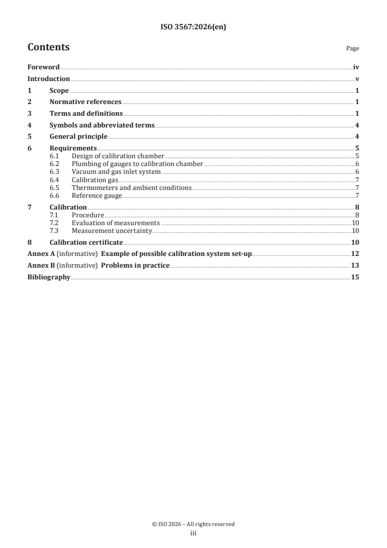
Contents Page
Foreword .iv
Introduction .v
1 Scope . 1
2 Normative references . 1
3 Terms and definitions . 1
4 Symbols and abbreviated terms. 4
5 General principle . 4
6 Requirements . 5
6.1 Design of calibration chamber .5
6.2 Plumbing of gauges to calibration chamber .6
6.3 Vacuum and gas inlet system .6
6.4 Calibration gas .7
6.5 Thermometers and ambient conditions .7
6.6 Reference gauge .7
7 Calibration . 8
7.1 Procedure .8
7.2 Evaluation of measurements .10
7.3 Measurement uncertainty . .10
8 Calibration certificate .10
Annex A (informative) Example of possible calibration system set-up.12
Annex B (informative) Problems in practice .13
Bibliography .15
iii
Foreword
ISO (the International Organization for Standardization) is a worldwide federation of national standards
bodies (ISO member bodies). The work of preparing International Standards is normally carried out through
ISO technical committees. Each member body interested in a subject for which a technical committee
has been established has the right to be represented on that committee. International organizations,
governmental and non-governmental, in liaison with ISO, also take part in the work. ISO collaborates closely
with the International Electrotechnical Commission (IEC) on all matters of electrotechnical standardization.
The procedures used to develop this document and those intended for its further maintenance are described
in the ISO/IEC Directives, Part 1. In particular, the different approval criteria needed for the different types
of ISO document should be noted. This document was drafted in accordance with the editorial rules of the
ISO/IEC Directives, Part 2 (see www.iso.org/directives).
ISO draws attention to the possibility that the implementation of this document may involve the use of (a)
patent(s). ISO takes no position concerning the evidence, validity or applicability of any claimed patent
rights in respect thereof. As of the date of publication of this document, ISO had not received notice of (a)
patent(s) which may be required to implement this document. However, implementers are cautioned that
this may not represent the latest information, which may be obtained from the patent database available at
www.iso.org/patents. ISO shall not be held responsible for identifying any or all such patent rights.
Any trade name used in this document is information given for the convenience of users and does not
constitute an endorsement.
For an explanation of the voluntary nature of standards, the meaning of ISO specific terms and expressions
related to conformity assessment, as well as information about ISO's adherence to the World Trade
Organization (WTO) principles in the Technical Barriers to Trade (TBT), see www.iso.org/iso/foreword.html.
This document was prepared by Technical Committee ISO/TC 112, Vacuum technology.
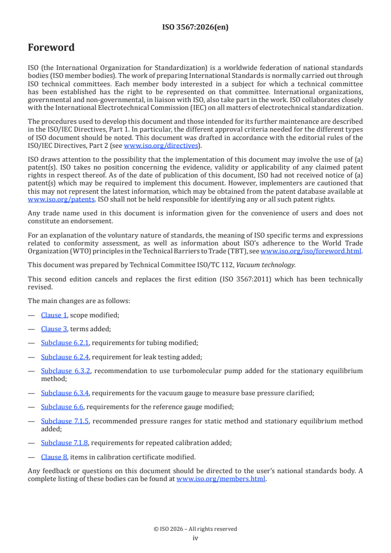
This second edition cancels and replaces the first edition (ISO 3567:2011) which has been technically
revised.
The main changes are as follows:
— Clause 1, scope modified;
— Clause 3, terms added;
— Subclause 6.2.1, requirements for tubing modified;
— Subclause 6.2.4, requirement for leak testing added;
— Subclause 6.3.2, recommendation to use turbomolecular pump added for the stationary equilibrium
method;
— Subclause 6.3.4, requirements for the vacuum gauge to measure base pressure clarified;
— Subclause 6.6, requirements for the reference gauge modified;
— Subclause 7.1.5, recommended pressure ranges for static method and stationary equilibrium method
added;
— Subclause 7.1.8, requirements for repeated calibration added;
— Clause 8, items in calibration certificate modified.
Any feedback or questions on this document should be directed to the user’s national standards body. A
complete listing of these bodies can be found at www.iso.org/members.html.
iv
Introduction
The document aims to establish the physical, technical and metrological conditions necessary for adequately
disseminating the pressure scale in the vacuum regime by calibration with a reference gauge. It is assumed
that users are familiar with the general procedures of vacuum generation and measurement in the vacuum
ranges considered.
v
International Standard ISO 3567:2026(en)
Vacuum gauges — Calibration by direct comparison with a
reference gauge
1 Scope
This document specifies the physical, technical and metrological conditions to be fulfilled when calibrations
of vacuum gauges are performed by direct comparison with a reference gauge at a calibration laboratory,
whether accredited or not. From the conditions described, the design of an apparatus that can perform
vacuum gauge calibrations in an adequate manner can be deduced.
This document is applicable for calibration of all types of vacuum gauges. Vacuum gauges can consist of
several parts; typically, these are: gauge head, cable, and control unit. This entire set is considered as the unit
to be calibrated. If only the gauge head (i.e. the part of the vacuum gauge directly exposed to the vacuum) is
calibrated, all set-ups and conditions are recorded such that the user of the calibrated gauge head is able to
perform the measurements in the same manner as during the calibration.
This document does not give guidance on how to treat special types of vacuum gauges, be they reference
standards or units under calibration.
The applicable pressure range for calibrations treated in this document depends on the realized design of
−6
the calibration apparatus and on the type of reference gauge, and the range varies in its limits from 10 Pa
to 133 kPa.
2 Normative references
The following documents are referred to in the text in such a way that some or all of their content constitutes
requirements of this document. For dated references, only the edition cited applies. For undated references,
the latest edition of the referenced document (including any amendments) applies.
ISO/IEC Guide 98-3, Uncertainty of measurement — Part 3: Guide to the expression of uncertainty in
me a s ur ement (GUM: 1995)
ISO/IEC 17025:2017, General requirements for the competence of testing and calibration laboratories
ISO 27893, Vacuum technology — Vacuum gauges — Evaluation of the uncertainties of results of calibrations by
direct comparison with a reference gauge
3 Terms and definitions
For the purposes of this document, the following terms and definitions apply.
ISO and IEC maintain terminology databases for use in standardization at the following addresses:
— ISO Online browsing platform: available at https:// www .iso .org/ obp
— IEC Electropedia: available at https:// www .electropedia .org/
3.1
primary standard
measurement standard established using a primary reference measurement procedure
[SOURCE: ISO/IEC Guide 99:2007, 5.4, modified — revised for simplification.]
3.2
national standard
measurement standard recognized by national authority to serve in a state or economy as the basis for
assigning quantity values to other measurement standards for the kind of quantity concerned
[SOURCE: ISO/IEC Guide 99:2007, 5.3]
3.3
reference standard
measurement standard designated for the calibration of other measurement standards for quantities of a
given kind in a given organization or at a given location
Note 1 to entry: In this document, "reference standard" is synonymous with "reference gauge".
[SOURCE: ISO/IEC Guide 99:2007, 5.6, modified — Note 1 to entry added.]
3.4
vacuum gauge
instrument for measuring gas or vapour pressure that is less than the prevailing atmospheric pressure
Note 1 to entry: Some types of vacuum gauges commonly in use do not measure a pressure directly, but measure some
other physical quantity which, under specific conditions, is related to pressure.
Note 2 to entry: For terms and definitions of the various vacuum gauges in use, see ISO 3529-3.
[SOURCE: ISO 3529-3:2014, 2.1.2, modified — Notes 1 and 2 to entry added.]
3.5
gauge head
part of the gauge which contains the pressure-sensitive element, and which is directly connected to the
vacuum system
Note 1 to entry: A gauge head comprising its operational device is usually called a transmitter.
[SOURCE: ISO 3529-3:2014, 2.1.2.1, modified — revised for simplification.]
3.6
control unit
controller
part of the gauge containing the power supply and all electrical circuitry
necessary for the operation of the gauge
[SOURCE: ISO 3529-3:2014, 2.1.2.2]
3.7
unit under calibration
UUC
vacuum gauge (3.4) to be calibrated
3.8
entrance flange
flange by which the unit under calibration (3.7) or the reference gauge is connected to the calibration chamber
(3.9)
3.9
calibration chamber
vacuum chamber that serves as a common vacuum medium for the reference gauge and unit under calibration
(3.7)
3.10
entrance mouth
opening in the calibration chamber (3.9) which leads to a unit under calibration (3.7), reference gauge or any
other part of the calibration system
3.11
calibration gas
gas species or mixture that is used to change the pressure in the calibration chamber (3.9)
3.12
sorption
taking up of a gas or vapour by a solid or liquid
[SOURCE: ISO 3529-1:2019, 3.4.1, modified — revised for simplification.]
3.13
desorption
liberation of gases or vapours sorbed by a material
[SOURCE: ISO 3529-1:2019, 3.4.14]
3.14
outgassing rate
throughput which is outgassed at a given time from a surface exposed to vacuum
[SOURCE: ISO 3529-1:2019, 3.4.18, modified — revised for simplification.]
3.15
base pressure
pressure in the calibration chamber (3.9) that exists either before gas is admitted into the calibration chamber
(3.9) for calibration, or later, after the gas inlet valve has been turned off for some time
Note 1 to entry: Base pressure is sometimes denoted as residual pressure.
3.16
base pressure reading
pressure reading of vacuum gauge (3.4) at the base pressure (3.15)
Note 1 to entry: Base pressure reading is denoted as “zero reading” when the base pressure (3.15) is lower than the
measurement limit of the gauge. For a spinning rotor gauge, this is also denoted as “offset”.
3.17
calibration pressure
pressure evaluated from the corrected reading of the reference gauge and all necessary corrections at the
gauge port of the unit under calibration (3.7)
EXAMPLE Pressure difference between gauge ports due to pressure distribution in the calibration chamber (3.9)
can be corrected.
3.18
error of reading in absolute unit
pressure reading of unit under calibration (3.7) minus calibration pressure (3.17)
3.19
error of reading in relative unit
e
relative error
error of reading in absolute unit (3.18) divided by calibration pressure (3.17)
3.20
static method
calibration method for which the valve to the pump system is closed and gas is admitted into the calibration
chamber (3.9) until the required pressure value is reached, so that the pressure in the calibration chamber
(3.9) remains stable in the calibration period of each pressure point
3.21
stationary equilibrium method
calibration method for which the valve to the pump system remains fully open or is partly closed and gas is
admitted into the calibration chamber (3.9) until the required pressure value is reached, so that the pressure
in the calibration chamber (3.9) remains stable in the calibration period of each pressure point
4 Symbols and abbreviated terms
Symbol or
Designation Unit
abbreviated term
D diameter of cylinder mm
e error of reading in relative unit in relative units
p base pressure Pa
p calibration pressure Pa
cal
p indicated pressure Pa
ind
Q outgassing rate Pa⋅m /s
out
S effective pumping speed m /s
eff
S sensitivity (coefficient) depends on definition
u standard uncertainty depends on quantity
u relative standard uncertainty none
r
U expanded uncertainty depends on quantity
U relative expanded uncertainty none
r
CF correction factor none
UUC unit under calibration (vacuum gauge) ‐
5 General principle
The UUC is connected to the same calibration chamber as the reference gauge.
Calibration of a vacuum gauge — the UUC — by comparison with a reference gauge is done by exposing the
entrance flange of the UUC and that of the reference gauge to the same density and velocity distribution of
calibration gas molecules. The same density and velocity distribution of these molecules means the same
pressure at the two locations, but not vice versa. Since there are many types of vacuum gauges that do not
measure pressure — but instead, for example, gas density or the impingement rate of gas molecules —
the above requisite is both necessary and more stringent than only calling for equal pressures at the two
entrance flanges.
The gas density (pressure) in the calibration chamber can be varied and the gauge readings of the UUC
compared with the pressures indicated by the reference gauge.
From this general principle, the requirements (see Clause 6) for the design of the calibration apparatus are
deduced.
6 Requirements
6.1 Design of calibration chamber
The chamber shall be designed to ensure that the distribution of gas in the measuring volume is sufficiently
uniform in space and stable in time (see Figure A.1).
In addition, the material of the calibration chamber shall be chosen such that the base pressure, p , is low
enough to perform the calibrations, as expressed by Formula (1) (see also 6.3):
Q
out
p = (1)
S
eff
where S is the effective pumping speed and Q is the total outgassing rate in the calibration chamber
eff out
which depends on pumping time, temperature, and the number and conditions of attached vacuum gauges.
In detail, the calibration chamber shall be designed and operated as follows. However, design criteria a) to
e) may be disregarded when the minimum calibration pressures to be realized in the vacuum chamber are
larger than 100 Pa and only static pressures (see 7.1) are established. Independent of pressure, criteria b) to
d) may be disregarded when only static pressures are established.
a) The calibration chamber shall have a volume of at least 20 times the total volume of all the gauges and
associated pipe work connecting the chamber and the gauges (e.g. elbows shall be considered as part of
the gauge volume).
b) The shape of the calibration chamber (see Figure 1) shall be cylinder-symmetrical to at least one axis.
A sphere is ideal, but two symmetrical domes, each a part of a sphere and attached to one another, or
cylinders, are equally possible. Where a cylinder is used, its overall length shall be within one and two
times its diameter, and domed ends are recommended.
c) The centre of the cross-sectional area of the pumping outlet and the gas inlet (if applicable) shall lie
on the same cylindrical axis of symmetry of the calibration chamber. The gas inlet may be positioned
between the pump outlet and pump system (see 6.3), in which case there is no need to have the gas inlet
on the axis of symmetry.
d) All entrance mouths and the axis of their respective tubes to which either the UUCs or the reference
gauges are to be connected shall be on a common equatorial plane, perpendicular to the cylindrical axis
of symmetry chosen for the pumping outlet (see Annex A).
Where a cylinder is used, it is recommended that this equatorial plane separate the cylinder into two halves
of equal length. Where a cylinder with a length of (3/2)D in relation to its diameter is used (suitable for
pump speed measurements), the gauges may be placed at one third of the length (D/2) above the bottom
flange.
e) Temperature differences between arbitrary points across the calibration chamber shall be less than 1 K.
Points closer than 5 cm from the entrance mouth to a heated vacuum gauge head (e.g. ionization gauge)
may be disregarded.
f) The spatial mean temperature [see e)] of the calibration chamber shall be (23 ± 3) °C during calibration,
while the mean temperature should not change by more than 1 K.
If the design criteria a) to e) are not fulfilled, the possible correction owing to unequal molecular density and
velocity distribution at the entrance flanges of the reference gauge and UUC (see 7.3) shall be measured and
the uncertainty of the correction term estimated.
a) b) c)
Figure 1 — Examples of possible calibration chamber shapes
6.2 Plumbing of gauges to calibration chamber
6.2.1 In order to minimize unbalanced molecular (pressure) distribution from sorption, gauge pumping
and outgassing etc., the tubing connecting the calibration chamber and the gauges shall be as short as
possible and shall have a diameter of at least the open area of the entrance flange of the gauge if the stationary
equilibrium method is used. In cases where the UUC or the reference gauge imposes a significant heat load
[see 6.1 e] on the calibration chamber, the tube length may be increased to reduce thermal conductance.
6.2.2 Care shall be taken to ensure that the simultaneous operation of the reference gauges and UUC does
not result in any significant mutual influence of their respective readings in steady operation. An influence
on the order of the uncertainty of the base pressure is acceptable.
NOTE The mutual influence can be checked by observing the reading of a gauge when switching another gauge off
and on.
6.2.3 No significant ambient air flow cooling or heating of the UUC or reference gauge shall be present. A
protective cover can be necessary.
6.2.4 Leak tests shall be carried out to verify that there are no significant leaks in the calibration chamber.
6.3 Vacuum and gas inlet system
6.3.1 The base pressure, p , in the calibration chamber shall be less than one tenth of the lowest pressure,
p , realized for a calibration, as determined by the reference gauge.
cal
The vacuum pump and its tubing to the calibration chamber shall be sized accordingly.
Lowest uncertainties due to the base pressure effect can be achieved if the value of the base pressure
is below the resolution limit of the UUC and/or reference gauge. It is strongly recommended that a base
pressure lower than the resolution limit of the UUC and/or reference gauge be established, if this resolution
limit is greater than or equal to 1 mPa.
Where a low base pressure in the
...