

ISO 15589-1:2026
(Main)Oil and gas industries including lower carbon energy — Cathodic protection of pipeline transportation systems — Part 1: On-land pipelines
- Abstract
This document specifies requirements and gives recommendations for the pre-installation surveys, design, materials, equipment, installation, commissioning, operation, inspection, and maintenance of cathodic protection systems for the external surface of on-land pipelines. This document is applicable to on-land pipelines and piping systems used in other industries and transporting other media such as industrial gases, waters, or slurries. Throughout this document, on-land pipelines mean: pipelines that are buried; landfalls of offshore pipeline sections protected by onshore based cathodic protection installations; immersed sections of on-land pipelines such as river or lake crossings. This document is applicable to pipelines of carbon steel, stainless steel, cast iron, galvanized steel, and copper. This document does not apply to pipelines made of reinforced concrete (see ISO 12696).
- Status
- Published
- Publication Date
- 12-Jul-2026
- Technical Committee
- ISO/TC 67/SC 2 - Pipeline transportation systems
- Drafting Committee
- ISO/TC 67/SC 2 - Pipeline transportation systems
- Current Stage
- 6060 - International Standard published
- Start Date
- 13-Jul-2026
- Due Date
- 20-Apr-2026
- Completion Date
- 13-Jul-2026
Buy Documents

ISO 15589-1:2026 - Oil and gas industries including lower carbon energy — Cathodic protection of pipeline transportation systems — Part 1: On-land pipelines

ISO 15589-1:2026 - Industries du pétrole et du gaz y compris les énergies à faible teneur en carbone — Protection cathodique des systèmes de transport par conduites — Partie 1: Conduites terrestres
ISO 15589-1:2026 is an International Standard from ISO for cathodic protection of pipeline transportation systems in the oil and gas industries including lower carbon energy. It specifies requirements and recommendations for the external corrosion protection of on-land pipelines, including buried lines, landfalls protected from onshore systems, and immersed river or lake crossings. It is written for the people who design, install, commission, inspect, and maintain these systems.
What does ISO 15589-1:2026 specify?
ISO 15589-1:2026 specifies how to plan, design, build, commission, operate, inspect, and maintain cathodic protection (CP) systems for the external surface of on-land pipelines. It applies to pipeline and piping systems in other industries too, when they carry media such as industrial gases, water, or slurries.
The standard covers carbon steel, stainless steel, cast iron, galvanized steel, and copper pipelines. It excludes reinforced concrete pipelines and points readers to ISO 12696 for that case.
The document is organized into clauses on scope, normative references, terms, symbols, competence, protection criteria, prerequisites, design, impressed current stations, galvanic anode systems, monitoring facilities, commissioning, monitoring and maintenance, and documentation. It is supported by seven annexes.
| Annex | What it covers |
|---|---|
| Annex A | Cathodic protection measurements |
| Annex B | Electrical interference |
| Annex C | Fault detection of impressed-current systems during operation |
| Annex D | Description of specialized surveys |
| Annex E | Calculation of the CP potential attenuation |
| Annex F | Electrical tests for isolation joints before installation |
| Annex G | Internal corrosion at insulating flange |
What are the key requirements of ISO 15589-1:2026?
ISO 15589-1:2026 focuses on getting the whole CP system to work as an integrated corrosion-control measure, not just on selecting an anode or setting a rectifier. The most important requirements are about competence, protection criteria, electrical continuity and isolation, system design, monitoring, commissioning, and records.
Competence and responsibility
ISO 15589-1:2026 requires people who design, supervise installation, commission, operate, measure, monitor, and maintain CP systems to have the right competence for their task. The note points to certification under ISO 15257, or an equivalent scheme from a body that conforms with ISO/IEC 17024. In practice, the standard expects CP work to be done by qualified people, not treated as routine electrical work.
Protection criteria and potential limits
ISO 15589-1:2026 sets CP criteria in terms of IR free potential and gives material-specific protection potentials and critical negative limits in Clause 6. The standard also warns that potentials that are too negative can damage coatings or create hydrogen-related risks on susceptible metals. In practice, operators must measure the right potential, interpret it against the right criterion, and avoid overprotection as well as underprotection.
The standard allows alternative assessment methods when the main criterion cannot be applied, including the 100 mV cathodic potential shift method, but only under defined conditions. It also says that AC interference and fluctuating DC interference change how protection is assessed, and that detailed criteria from ISO 18086 and ISO 21857 apply where those influences are present. That matters because a pipeline can look protected in one reading and still suffer corrosion if interference is not handled correctly.
Preconditions for applying CP
ISO 15589-1:2026 requires the pipeline section to be electrically continuous and normally electrically isolated from foreign structures and earthing systems. Coating quality, coating repairs, trench backfill, and casings all matter because they affect current demand and interference risk. The standard also addresses isolation joints, lightning and overvoltage protection, and devices for DC decoupling.
For buried pipelines, Clause 7 says the trench backfill may need added material such as washed sand or fine soil to avoid coating damage and shielding effects. For AC interference, the standard allows mitigation systems and additional earthing, but expects them to be arranged so they do not undermine CP. For DC interference, it points to drainage stations, isolation joints, stronger protection in anodic zones, and conformity with the relevant interference standard.
Design, equipment, and anode systems
ISO 15589-1:2026 requires the CP design to be based on the pipeline geometry, coating, environment, operating temperature, nearby structures, interference sources, and other site data. The design report shall document the design life, sizing and layout of equipment, temporary CP, installation procedures, commissioning procedures, and operation and maintenance instructions. This means the design is a documented engineering package, not just a calculation sheet.
For impressed current systems, the standard gives guidance on power supply, ground beds, output control, and remote monitoring. It says transformer-rectifier units are the normal DC source and notes that outputs above 50 V DC should generally be avoided. For galvanic systems, it limits use to low-current-demand situations and requires the anode mass, utilization factor, backfill, and current output to be checked against the design life.
The standard also gives practical guidance for zinc and magnesium anodes, including when each is suitable in soil and when backfill should be used. It expects anodes to be installed in accessible, effective locations and their cable connections to allow later measurement. For the reader, this means anode choice and placement are part of the corrosion design, not an afterthought.
Monitoring, commissioning, and maintenance
ISO 15589-1:2026 requires test stations and other monitoring facilities along the route so CP performance can be measured. Test stations should be placed at intervals not greater than 3 km in rural areas and 1 km in urban or industrial areas, and also at special features such as isolation joints, casings, bonds, drainage stations, and CP installations. The standard also supports probes and coupons where ordinary pipe-to-soil measurements are not enough.
Commissioning is a three-step process: preliminary tests, start-up, and verification of effectiveness. The commissioning checks include electrical integrity, correct connections, isolation tests, measurements of potentials and currents, and confirmation that the system meets the Clause 6 criteria. After that, the system must be monitored at regular intervals, with inspection frequency based on site conditions, interference risk, system type, coating quality, and pipeline history.
Remote monitoring is allowed and can extend field intervals if it gives the same information and still detects deterioration or failure. Maintenance duties include correcting inadequate protection, investigating significant positive shifts, and keeping insulating devices clean and functional. In practice, the standard treats monitoring records as part of corrosion control, not just paperwork.
What terms does ISO 15589-1:2026 define?
ISO 15589-1:2026 defines the terms needed to specify CP work consistently across design, testing, and maintenance.
- Cathodic protection system - The complete set of equipment used to apply cathodic protection, including impressed current installations, power supplies, anodes, monitoring facilities, bonds, and cables.
- IR free potential - The pipeline-to-electrolyte potential without the voltage error caused by IR drop in the current path.
- Isolation joint - An insulating component between pipe lengths that prevents electrical continuity.
- Coupon - A metal sample of defined area and thickness used to measure conditions relevant to CP and corrosion.
- Probe - A device that includes a coupon and is used to assess CP effectiveness and/or corrosion risk.
- Stray current - Current flowing by a path other than the intended circuit.
- Utilization factor - The fraction of an anode’s mass that can be consumed before it can no longer deliver the required current.
- On-land pipeline - A pipeline laid on or in land, including lines under inland water courses.
Who uses ISO 15589-1:2026?
ISO 15589-1:2026 is used by pipeline corrosion engineers, CP designers, and integrity engineers who need to size and specify CP systems. It is also used by construction contractors, commissioning teams, and inspection personnel who install, test, and verify CP equipment in the field.
Operators and maintenance teams use it to set monitoring plans, inspection intervals, and repair actions. Quality managers and buyers use it when they need to check that a pipeline project includes suitable CP design, materials, documentation, and long-term inspection provisions. It is relevant to oil and gas pipelines and also to on-land pipeline systems carrying other media in other industries.
What changed in ISO 15589-1:2026 from the previous edition?
ISO 15589-1:2026 cancels and replaces ISO 15589-1:2015 as a technically revised third edition. The foreword states that the main changes are expanded cathodic protection criteria with clearer application guidance, more detailed design requirements, longer inspection periodicities with remote monitoring added, and more detailed commissioning measurements and testing.
Which standards are used with ISO 15589-1:2026?
ISO 15589-1:2026 cites these normative references, each of which contributes a specific part of the CP framework:
- ISO 8044 - Vocabulary for corrosion terms.
- ISO 10012 - Requirements for measurement processes and measuring equipment.
- ISO 13623 - General pipeline transportation system requirements.
- ISO 13847 - Welding of pipelines.
- ISO 21809-3 - Field joint coatings for buried or submerged pipelines.
- ISO 21809-5 - External concrete coatings for buried or submerged pipelines.
- ISO 21857 - Prevention of corrosion on pipeline systems influenced by stray currents.
- IEC 60079-10-1 - Classification of explosive gas atmospheres.
- IEC 60529 - IP Code for enclosure protection.
- IEC 62561-3 - Requirements for isolating spark gaps.
- EN 1594 - Functional requirements for gas pipelines above 16 bar.
- EN 12007-3 - Functional recommendations for steel gas pipelines up to 16 bar.
- EN 14161 - Pipeline transportation systems requirements used as a reference in the gas sector.
What does the ISO 15589-1:2026 document contain?
ISO 15589-1:2026 contains the technical basis for CP design and verification, including material-specific protection criteria, design inputs, current demand calculations, anode sizing, and station layouts. It also contains practical guidance on coatings, casings, trench backfill, trenchless installation, interference mitigation, and test facility placement.
Annex A provides measurement procedures for on-potential, instant-off potential, true current, polarization, depolarization, corrosion rate, electrical isolation, and line current. Annex B covers DC and AC interference sources, measurement, and mitigation. Annex D describes survey methods such as ACVG, CIPS, current-attenuation surveys, direct-current voltage gradient surveys, intensive measurement techniques, and current injection tests.
Annex E gives equations and worked examples for CP potential attenuation along a pipeline, which helps with spacing drain points and estimating current distribution. Annex F describes electrical tests for isolation joints before installation, and Annex G explains internal corrosion risks at insulating flanges and the related protective measures.
Relations
- Effective Date
- 12-Feb-2026
- Effective Date
- 22-Apr-2023
Buy Documents
ISO 15589-1:2026 - Oil and gas industries including lower carbon energy — Cathodic protection of pipeline transportation systems — Part 1: On-land pipelines
ISO 15589-1:2026 - Industries du pétrole et du gaz y compris les énergies à faible teneur en carbone — Protection cathodique des systèmes de transport par conduites — Partie 1: Conduites terrestres
Get Certified
Connect with accredited certification bodies for this standard

Element Materials Technology
Materials testing and product certification.

ABS Group Brazil
ABS Group certification services in Brazil.

ABS Quality Evaluations Inc.
American Bureau of Shipping quality certification.
Sponsored listings
Frequently Asked Questions
ISO 15589-1:2026 is a standard published by the International Organization for Standardization (ISO). Its full title is "Oil and gas industries including lower carbon energy — Cathodic protection of pipeline transportation systems — Part 1: On-land pipelines". This standard covers: This document specifies requirements and gives recommendations for the pre-installation surveys, design, materials, equipment, installation, commissioning, operation, inspection, and maintenance of cathodic protection systems for the external surface of on-land pipelines. This document is applicable to on-land pipelines and piping systems used in other industries and transporting other media such as industrial gases, waters, or slurries. Throughout this document, on-land pipelines mean: pipelines that are buried; landfalls of offshore pipeline sections protected by onshore based cathodic protection installations; immersed sections of on-land pipelines such as river or lake crossings. This document is applicable to pipelines of carbon steel, stainless steel, cast iron, galvanized steel, and copper. This document does not apply to pipelines made of reinforced concrete (see ISO 12696).
This document specifies requirements and gives recommendations for the pre-installation surveys, design, materials, equipment, installation, commissioning, operation, inspection, and maintenance of cathodic protection systems for the external surface of on-land pipelines. This document is applicable to on-land pipelines and piping systems used in other industries and transporting other media such as industrial gases, waters, or slurries. Throughout this document, on-land pipelines mean: pipelines that are buried; landfalls of offshore pipeline sections protected by onshore based cathodic protection installations; immersed sections of on-land pipelines such as river or lake crossings. This document is applicable to pipelines of carbon steel, stainless steel, cast iron, galvanized steel, and copper. This document does not apply to pipelines made of reinforced concrete (see ISO 12696).
ISO 15589-1:2026 is classified under the following ICS (International Classification for Standards) categories: 75.200 - Petroleum products and natural gas handling equipment. The ICS classification helps identify the subject area and facilitates finding related standards.
ISO 15589-1:2026 has the following relationships with other standards: It is inter standard links to EN ISO 15589-1:2026, ISO 15589-1:2015. Understanding these relationships helps ensure you are using the most current and applicable version of the standard.
ISO 15589-1:2026 is available in PDF format for immediate download after purchase. The document can be added to your cart and obtained through the secure checkout process. Digital delivery ensures instant access to the complete standard document.
Standards Content (Sample)
International
Standard
ISO 15589-1
Third edition
Oil and gas industries including
2026-07
lower carbon energy —
Cathodic protection of pipeline
transportation systems —
Part 1:
On-land pipelines
Industries du pétrole et du gaz y compris les énergies à faible
teneur en carbone — Protection cathodique des systèmes de
transport par conduites —
Partie 1: Conduites terrestres
Reference number
© ISO 2026
All rights reserved. Unless otherwise specified, or required in the context of its implementation, no part of this publication may
be reproduced or utilized otherwise in any form or by any means, electronic or mechanical, including photocopying, or posting on
the internet or an intranet, without prior written permission. Permission can be requested from either ISO at the address below
or ISO’s member body in the country of the requester.
ISO copyright office
CP 401 • Ch. de Blandonnet 8
CH-1214 Vernier, Geneva
Phone: +41 22 749 01 11
Email: copyright@iso.org
Website: www.iso.org
Published in Switzerland
ii
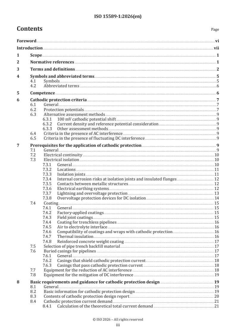
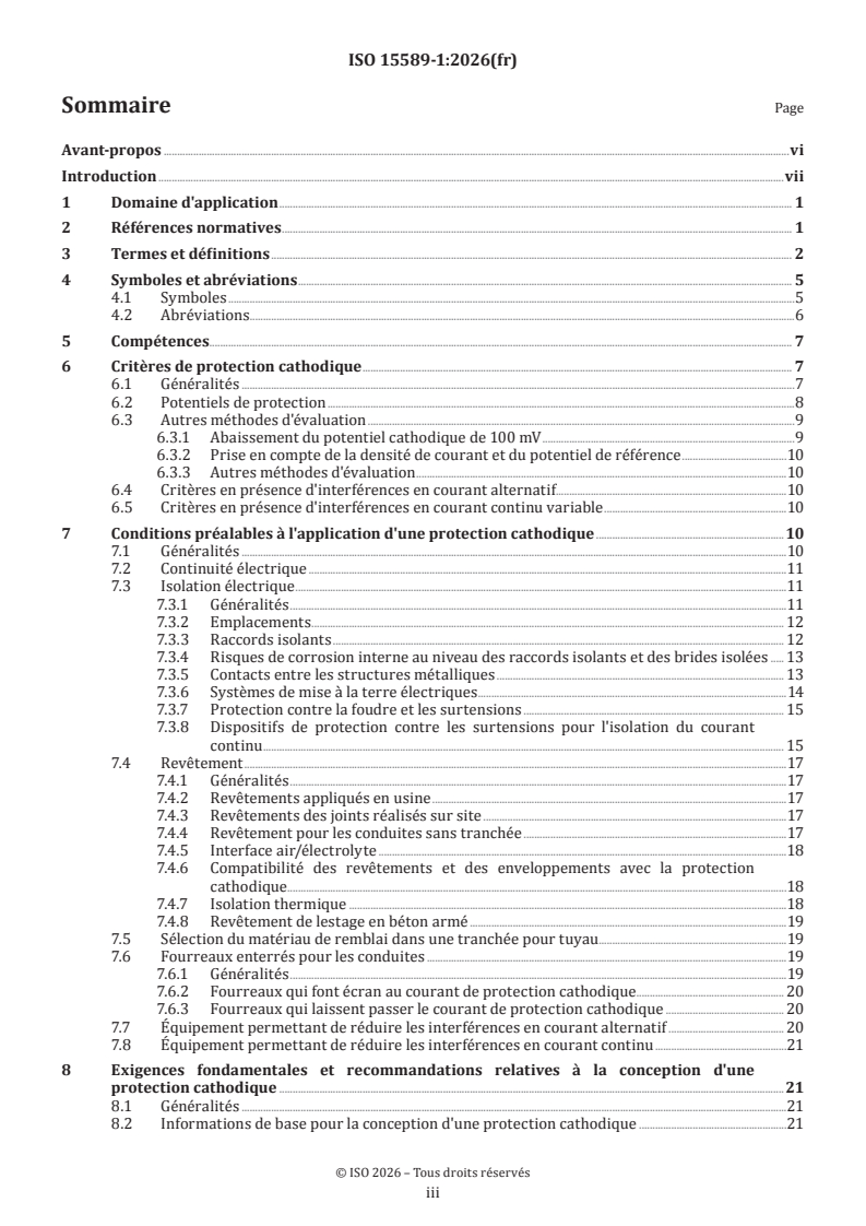
Contents Page
Foreword .vi
Introduction .vii
1 Scope . 1
2 Normative references . 1
3 Terms and definitions . 2
4 Symbols and abbreviated terms. 5
4.1 Symbols .5
4.2 Abbreviated terms .6
5 Competence . 6
6 Cathodic protection criteria . 7
6.1 General .7
6.2 Protection potentials .7
6.3 Alternative assessment methods .9
6.3.1 100 mV cathodic potential shift .9
6.3.2 Current density and reference potential consideration .9
6.3.3 Other assessment methods .9
6.4 Criteria in the presence of AC interference .9
6.5 Criteria in the presence of fluctuating DC interference .9
7 Prerequisites for the application of cathodic protection . 9
7.1 General .9
7.2 Electrical continuity .10
7.3 Electrical isolation .10
7.3.1 General .10
7.3.2 Locations .11
7.3.3 Isolation joints .11
7.3.4 Internal corrosion risks at isolation joints and insulated flanges . 12
7.3.5 Contacts between metallic structures. 12
7.3.6 Electrical earthing systems . . 12
7.3.7 Lightning and overvoltage protection . 13
7.3.8 Overvoltage protection devices for DC isolation .14
7.4 Coating . 15
7.4.1 General . 15
7.4.2 Factory-applied coatings . 15
7.4.3 Field joint coatings . 15
7.4.4 Coating for trenchless pipelines .16
7.4.5 Air to electrolyte interface .16
7.4.6 Compatibility of coatings and wraps with cathodic protection .16
7.4.7 Thermal insulation .16
7.4.8 Reinforced concrete weight coating .17
7.5 Selection of pipe trench backfill material.17
7.6 Buried casings for pipelines .17
7.6.1 General .17
7.6.2 Casings that shield cathodic protection current .18
7.6.3 Casings that pass cathodic protection current .18
7.7 Equipment for the reduction of AC interference .18
7.8 Equipment for the mitigation of DC interference .19
8 Basic requirements and guidance for cathodic protection design . 19
8.1 General .19
8.2 Basic information for cathodic protection design .19
8.3 Contents of cathodic protection design report . 20
8.4 Cathodic protection current demand .21
8.4.1 Calculation of the theoretical total current demand .21
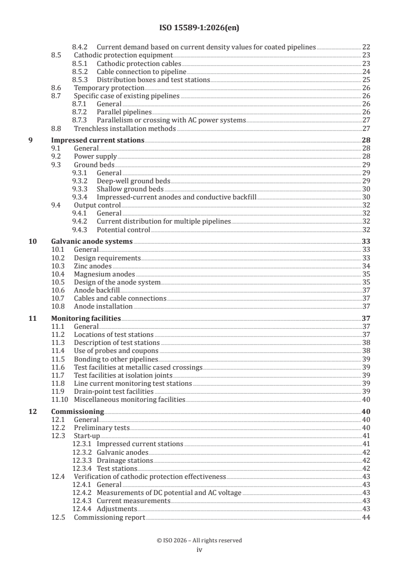
iii
8.4.2 Current demand based on current density values for coated pipelines . 22
8.5 Cathodic protection equipment . 23
8.5.1 Cathodic protection cables . 23
8.5.2 Cable connection to pipeline .24
8.5.3 Distribution boxes and test stations . 25
8.6 Temporary protection . 26
8.7 Specific case of existing pipelines . 26
8.7.1 General . 26
8.7.2 Parallel pipelines . 26
8.7.3 Parallelism or crossing with AC power systems .27
8.8 Trenchless installation methods .27
9 Impressed current stations .28
9.1 General . 28
9.2 Power supply . 28
9.3 Ground beds . 29
9.3.1 General . 29
9.3.2 Deep-well ground beds . 29
9.3.3 Shallow ground beds . 30
9.3.4 Impressed-current anodes and conductive backfill . 30
9.4 Output control .32
9.4.1 General .32
9.4.2 Current distribution for multiple pipelines .32
9.4.3 Potential control .32
10 Galvanic anode systems .33
10.1 General . 33
10.2 Design requirements . 33
10.3 Zinc anodes . 34
10.4 Magnesium anodes . 35
10.5 Design of the anode system. 35
10.6 Anode backfill.37
10.7 Cables and cable connections .37
10.8 Anode installation .37
11 Monitoring facilities .37
11.1 General .37
11.2 Locations of test stations .37
11.3 Description of test stations . 38
11.4 Use of probes and coupons . 38
11.5 Bonding to other pipelines . 39
11.6 Test facilities at metallic cased crossings . 39
11.7 Test facilities at isolation joints . 39
11.8 Line current monitoring test stations . 39
11.9 Drain-point test facilities . 39
11.10 Miscellaneous monitoring facilities . 40
12 Commissioning.40
12.1 General . 40
12.2 Preliminary tests . . 40
12.3 Start-up .41
12.3.1 Impressed current stations .41
12.3.2 Galvanic anodes .42
12.3.3 Drainage stations .42
12.3.4 Test stations.42
12.4 Verification of cathodic protection effectiveness .43
12.4.1 General .43
12.4.2 Measurements of DC potential and AC voltage .43
12.4.3 Current measurements .43
12.4.4 Adjustments .43
12.5 Commissioning report . 44
iv
12.5.1 Installation documentation . 44
12.5.2 Commissioning data and information . 44
13 Monitoring, inspection and maintenance .45
13.1 General .45
13.2 Implementation of inspection .45
13.3 Inspection intervals . 46
13.4 Remote monitoring . 48
13.5 Specialized surveys . 48
13.6 Monitoring plan . 48
13.7 Measuring equipment . 49
13.8 Maintenance and repair . 49
14 Documentation .50
14.1 Design documentation . 50
14.1.1 General . 50
14.1.2 Construction details and installation procedures . 50
14.2 Commissioning documentation . .51
14.3 Operating and maintenance documentation .51
14.3.1 General .51
14.3.2 Inspection and monitoring data .52
14.3.3 Maintenance records .52
Annex A (normative) Cathodic protection measurements .53
Annex B (normative) Electrical interference . 61
Annex C (informative) Fault detection of impressed-current systems during operation .65
Annex D (informative) Description of specialized surveys . 67
Annex E (informative) Calculation of the CP potential attenuation . 74
Annex F (informative) Electrical tests for isolation joints before installation .79
Annex G (informative) Internal corrosion at insulating flange .80
Bibliography .83
v
Foreword
ISO (the International Organization for Standardization) is a worldwide federation of national standards
bodies (ISO member bodies). The work of preparing International Standards is normally carried out through
ISO technical committees. Each member body interested in a subject for which a technical committee
has been established has the right to be represented on that committee. International organizations,
governmental and non-governmental, in liaison with ISO, also take part in the work. ISO collaborates closely
with the International Electrotechnical Commission (IEC) on all matters of electrotechnical standardization.
The procedures used to develop this document and those intended for its further maintenance are described
in the ISO/IEC Directives, Part 1. In particular, the different approval criteria needed for the different types
of ISO document should be noted. This document was drafted in accordance with the editorial rules of the
ISO/IEC Directives, Part 2 (see www.iso.org/directives).
ISO draws attention to the possibility that the implementation of this document may involve the use of (a)
patent(s). ISO takes no position concerning the evidence, validity or applicability of any claimed patent
rights in respect thereof. As of the date of publication of this document, ISO had not received notice of (a)
patent(s) which may be required to implement this document. However, implementers are cautioned that
this may not represent the latest information, which may be obtained from the patent database available at
www.iso.org/patents. ISO shall not be held responsible for identifying any or all such patent rights.
Any trade name used in this document is information given for the convenience of users and does not
constitute an endorsement.
For an explanation of the voluntary nature of standards, the meaning of ISO specific terms and expressions
related to conformity assessment, as well as information about ISO's adherence to the World Trade
Organization (WTO) principles in the Technical Barriers to Trade (TBT), see www.iso.org/iso/foreword.html.
This document was prepared by Technical Committee ISO/TC 67, Oil and gas industries including lower carbon
energy, Subcommittee SC 2, Pipeline transportation systems, in collaboration with the European Committee
for Standardization (CEN) Technical Committee CEN/TC 219, Cathodic protection, in accordance with the
Agreement on technical cooperation between ISO and CEN (Vienna Agreement).
This third edition cancels and replaces the second edition (ISO 15589-1:2015), which has been technically
revised.
The main changes are as follows:
— cathodic protection criteria have been extended with further clarification on the application of the
criteria;
— requirements for design have been more detailed; periodicities for inspection of cathodic equipment
have been enlarged; and the option for remote monitoring has been added;
— requirements for measurements and testing during commissioning have been further detailed.
A list of all parts in the ISO 15589 series can be found on the ISO website.
Any feedback or questions on this document should be directed to the user’s national standards body. A
complete listing of these bodies can be found at www.iso.org/members.html.
vi
Introduction
Pipeline cathodic protection is achieved by the supply of sufficient direct current to the external pipe
surface, so that the steel-to-electrolyte potential is lowered to values at which external corrosion is reduced
to an insignificant rate.
Cathodic protection is normally used in combination with a suitable protective coating system to protect
the external surfaces of steel pipelines from corrosion.
vii
International Standard ISO 15589-1:2026(en)
Oil and gas industries including lower carbon energy —
Cathodic protection of pipeline transportation systems —
Part 1:
On-land pipelines
1 Scope
This document specifies requirements and gives recommendations for the pre-installation surveys, design,
materials, equipment, installation, commissioning, operation, inspection, and maintenance of cathodic
protection systems for the external surface of on-land pipelines.
This document is applicable to on-land pipelines and piping systems used in other industries and
transporting other media such as industrial gases, waters, or slurries.
Throughout this document, on-land pipelines mean:
— pipelines that are buried;
— landfalls of offshore pipeline sections protected by onshore based cathodic protection installations;
— immersed sections of on-land pipelines such as river or lake crossings.
This document is applicable to pipelines of carbon steel, stainless steel, cast iron, galvanized steel, and
copper.
This document does not apply to pipelines made of reinforced concrete (see ISO 12696).
2 Normative references
The following documents are referred to in the text in such a way that some or all of their content constitutes
requirements of this document. For dated references, only the edition cited applies. For undated references,
the latest edition of the referenced document (including any amendments) applies.
ISO 8044, Corrosion of metals and alloys — Vocabulary
ISO 10012, Measurement management systems — Requirements for measurement processes and measuring
equipment
ISO 13623, Petroleum and natural gas industries — Pipeline transportation systems
ISO 13847, Petroleum and natural gas industries — Pipeline transportation systems — Welding of pipelines
ISO 21809-3, Oil and gas industries including lower carbon energy — External coatings for buried or submerged
pipelines used in pipeline transportation systems — Part 3: Field joint coatings
ISO 21809-5, Oil and gas industries including lower carbon energy — External coatings for buried or submerged
pipelines used in pipeline transportation systems — Part 5: External concrete coatings
ISO 21857, Petroleum, petrochemical and natural gas industries — Prevention of corrosion on pipeline systems
influenced by stray currents
IEC 60079-10-1, Explosive atmospheres — Part 10-1: Classification of areas — Explosive gas atmospheres
IEC 60529, Degrees of protection provided by enclosures (IP Code)
IEC 62561-3, Lightning protection system components (LPSC) - Part 3: Requirements for isolating spark gaps
(ISGs)
EN 1594, Gas infrastructure — Pipelines for maximum operating pressure over 16 bar — Functional
requirements
EN 12007-3, Gas infrastructure — Pipelines for maximum operating pressure up to and including 16 bar – Part
3: Specific functional recommendations for steel
EN 14161, Petroleum and natural gas industries — Pipeline transportation systems from 2011+A1 from 2015
(ISO 13623:2017)
3 Terms and definitions
For the purposes of this document, the terms and definitions given in ISO 8044 and the following apply.
ISO and IEC maintain terminology databases for use in standardization at the following addresses:
— ISO Online browsing platform: available at https:// www .iso .org/ obp
— IEC Electropedia: available at https:// www .electropedia .org/
3.1
anode backfill
added material immediately surrounding a buried anode
3.2
bond
conductor connecting two points on the same structure or between different structures
3.3
cathodic protection system
impressed current and galvanic anode system consisting of all the equipment necessary for the application
of cathodic protection, such as impressed current installations, power supplies, impressed current anodes
(3.12), galvanic anodes, monitoring facilities, bonds (3.2) and cables
3.4
coupon
metal sample of defined surface area and thickness made of a metal equivalent to the metal of the pipeline
3.5
coating defect
anomaly in the coating that results in the steel surface making direct contact with the surrounding
electrolyte
3.6
DC decoupling device
direct current decoupling device
equipment that provides a low-impedance path for alternating current and high resistance for direct current
EXAMPLE Polarization cells, capacitors, or diode assemblies.
3.7
drain point
location of the cable connection to the protected pipeline through which the protective current returns to
its source
3.8
drainage
transfer of stray current (3.24) between structures by means of a deliberate bond (3.2)
Note 1 to entry: See ISO 21857 for drainage devices (direct drainage bond, resistance drainage bond, unidirectional
drainage bond and forced drainage bond).
3.9
drainage station
equipment and materials required to provide drainage (3.8) of stray currents (3.24) from affected systems
3.10
galvanic anode station
equipment and materials required to provide cathodic protection by the use of galvanic anodes
Note 1 to entry: Such materials and equipment include galvanic anodes and cables.
3.11
ground bed
system of buried or immersed anodes
3.12
impressed current anode
electrode that delivers cathodic protection current in combination with an impressed current station (3.13)
3.13
impressed current station
equipment and materials required to provide cathodic protection by impressed current
Note 1 to entry: Such materials and equipment include impressed current anodes (3.12), cables, and a DC source.
3.14
IR drop
voltage that is the product of all currents flowing through the cathodic protection circuit and the resistance
of the current path (mainly the electrolyte and the pipeline)
Note 1 to entry: This is derived from Ohm’s law (U = I × R).
3.15
IR free potential
polarized potential
coating defect (3.5) or coupon (3.4) to electrolyte potential without the voltage error caused by the IR drop
(3.14) due to the protection current or any other current
3.16
isolation joint
electrically insulating component inserted between two lengths of pipe to prevent electrical continuity
between them
EXAMPLE Monobloc isolation joint, insulated flange.
3.17
spark gap
component with discharge distance for isolating electrically conductive installation sections
Note 1 to entry: In the event of lightning strike, the installation sections are temporarily connected conductively as
the result of response of the discharge.
3.18
local earth
conductive mass of the electrolyte, whose voltage between two reference electrodes at any point is not equal
to zero
3.19
measuring point
location where the actual potential measurement takes place
Note 1 to entry: In the case of pipe-to-electrolyte potential measurement, this refers to the location of the reference
electrode.
3.20
pipeline-to-electrolyte potential
difference in potential between a pipeline and a specified reference electrode in contact with the electrolyte
3.21
probe
device incorporating a coupon (3.4) that provides measurements of parameters used to assess the
effectiveness of cathodic protection and/or corrosion risk
3.22
remote earth
conductive mass of the electrolyte, whose voltage between two reference electrodes at any point is
conventionally taken as equal to zero
Note 1 to entry: This condition generally prevails outside the zone of influence of an earth electrode, an earthing
system, an anode ground bed (3.11), or a protected pipeline.
3.24
stray current
current flowing through paths other than the intended circuit
3.25
telluric current
current in the earth as a result of geomagnetic fluctuations
3.26
test station
monitoring station
installation that provides measuring and test facilities
Note 1 to entry: Such installations include cabling and pipeline connections.
3.27
trenchless installation
buried pipe installation methodology that does not require an open ditch
3.28
utilization factor
fraction of the anodic material weight of an anode that can be consumed before the anode ceases to provide
the minimum required current output
3.29
on-land pipeline
pipeline laid on or in land, including lines laid under inland water courses
Note 1 to entry: From the EN 14161 scope are excluded on-land supply systems used by the European gas supply
industry from the input of gas into the on-land transmission network up to the inlet connection of gas appliances.
3.30
coating breakdown factor
ratio of current density required to polarize a coated steel surface as compared to a bare steel surface
4 Symbols and abbreviated terms
4.1 Symbols
D anode diameter
a
D backfill diameter
b
E potential measured at the metal/electrolyte interface
∆E
potential shift due to cathodic protection current measured against a remote reference electrode
E open-circuit potential of a galvanic anode
a
E design protection potential
c
E free corrosion potential (also called natural potential)
cor
E potential at the metal/electrolyte interface, i.e. the potential that is free from the IR drop in the
IRfree
corrosive environment
E critical negative potential limit
l
E on-potential
ON
E instant-off potential
OFF
E protection potential criterion
p
E ON potential required to achieve effective cathodic protection
ref
I total current demand
tot
I actual end-of-life individual anode current output
af
I mean current demand
cm
I measured current on a coupon
cpn
I required end-of-life individual anode current output
f
j current density for bare steel
j current density for coated pipelines
c
J calculated current density on a coupon
cpn
J reference value for current density (analogous to I )
ref ref
k contingency factor
L length of the pipeline
m total net anode mass
m individual net anode mass
a
n number of anodes
r average coating resistance
co
R total circuit resistance for a galvanic anode cathodic protection system
a
R anode resistance relative to backfill
a/b
R backfill bed resistance relative to the natural electrolyte
b/s
ρ resistivity of an electrolyte
T temperature
t design life
dl
U voltage
u utilization factor
4.2 Abbreviated terms
AC alternating current
ACVG alternating current voltage gradient
CIPS close interval potential survey
CP cathodic protection
CSE copper−copper sulphate (saturated) reference electrode
DC direct current
DCVG direct current voltage gradient
ER electrical resistance
FBE fusion-bonded epoxy
I/J isolation joint
MMO mixed metal oxide
SRB sulphate reducing bacteria
UV ultraviolet
3LPE three-layer polyethylene
3LPP three-layer polypropylene
rms root mean square
5 Competence
Persons who undertake the design, supervision of installation, commissioning, supervision of operation,
measurements, monitoring, and supervision of maintenance of cathodic protection systems shall have the
appropriate level of competence for the tasks undertaken.
NOTE 1 Competence of cathodic protection persons to the level appropriate for tasks undertaken can be
demonstrated by certification in accordance with prequalification procedures such as ISO 15257 or by any other
equivalent scheme and issued by a certification body conforming with ISO/IEC 17024.
NOTE 2 This does not preclude documented confirmation of task-specific competence by bodies that are not
certification bodies.
6 Cathodic protection criteria
6.1 General
The corrosion rate of a metal in soil or water is a function of the electrode potential, E, of the material in its
surrounding media. The protection potential, E , depends on the metal in its environment. For carbon steel
p
and cast iron, the corrosion rate corresponding to E is considered to be 0,01 mm per year in the absence of
p
AC or fluctuating DC interference (in case of AC interference, see 6.4 or 6.5).
The criterion for CP is therefore, given by the condition in Formula (1):
E ≤ E (1)
IRfree p
The protection potential of a metal depends on the corrosive environment (e.g electrolyte) and on the type
of metal used (see Table 1).
Application of potentials that are too negative can result in coating disbondment and blistering and hydrogen
embrittlement of some metals.
The IR free potential, E , should not be more negative than the critical negative potential limit, E .
IRfree l
If E is defined, the criterion for CP is given by the conditions in Formula (2):
l
E ≤ E ≤ E (2)
l IRfree p
If the conditions in Formula (2) cannot be achieved to avoid coating
...
Norme
internationale
ISO 15589-1
Troisième édition
Industries du pétrole et du gaz
2026-07
y compris les énergies à faible
teneur en carbone — Protection
cathodique des systèmes de
transport par conduites —
Partie 1:
Conduites terrestres
Oil and gas industries including lower carbon energy — Cathodic
protection of pipeline transportation systems —
Part 1: On-land pipelines
Numéro de référence
DOCUMENT PROTÉGÉ PAR COPYRIGHT
© ISO 2026
Tous droits réservés. Sauf prescription différente ou nécessité dans le contexte de sa mise en œuvre, aucune partie de cette
publication ne peut être reproduite ni utilisée sous quelque forme que ce soit et par aucun procédé, électronique ou mécanique,
y compris la photocopie, ou la diffusion sur l’internet ou sur un intranet, sans autorisation écrite préalable. Une autorisation peut
être demandée à l’ISO à l’adresse ci-après ou au comité membre de l’ISO dans le pays du demandeur.
ISO copyright office
Case postale 401 • Ch. de Blandonnet 8
CH-1214 Vernier, Genève
Tél.: +41 22 749 01 11
E-mail: copyright@iso.org
Web: www.iso.org
Publié en Suisse
ii
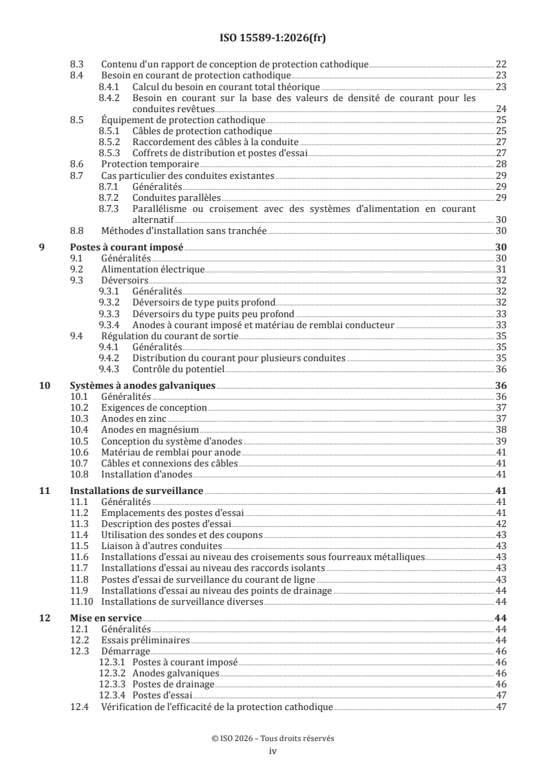
Sommaire Page
Avant-propos .vi
Introduction .vii
1 Domaine d'application . 1
2 Références normatives . 1
3 Termes et définitions . 2
4 Symboles et abréviations . 5
4.1 Symboles .5
4.2 Abréviations.6
5 Compétences . . 7
6 Critères de protection cathodique . 7
6.1 Généralités .7
6.2 Potentiels de protection .8
6.3 Autres méthodes d'évaluation .9
6.3.1 Abaissement du potentiel cathodique de 100 mV .9
6.3.2 Prise en compte de la densité de courant et du potentiel de référence .10
6.3.3 Autres méthodes d'évaluation .10
6.4 Critères en présence d'interférences en courant alternatif.10
6.5 Critères en présence d'interférences en courant continu variable .10
7 Conditions préalables à l'application d'une protection cathodique .10
7.1 Généralités .10
7.2 Continuité électrique .11
7.3 Isolation électrique .11
7.3.1 Généralités .11
7.3.2 Emplacements . 12
7.3.3 Raccords isolants . 12
7.3.4 Risques de corrosion interne au niveau des raccords isolants et des brides isolées . 13
7.3.5 Contacts entre les structures métalliques . 13
7.3.6 Systèmes de mise à la terre électriques .14
7.3.7 Protection contre la foudre et les surtensions . 15
7.3.8 Dispositifs de protection contre les surtensions pour l'isolation du courant
continu . 15
7.4 Revêtement .17
7.4.1 Généralités .17
7.4.2 Revêtements appliqués en usine .17
7.4.3 Revêtements des joints réalisés sur site .17
7.4.4 Revêtement pour les conduites sans tranchée .17
7.4.5 Interface air/électrolyte .18
7.4.6 Compatibilité des revêtements et des enveloppements avec la protection
cathodique . .18
7.4.7 Isolation thermique .18
7.4.8 Revêtement de lestage en béton armé .19
7.5 Sélection du matériau de remblai dans une tranchée pour tuyau .19
7.6 Fourreaux enterrés pour les conduites .19
7.6.1 Généralités .19
7.6.2 Fourreaux qui font écran au courant de protection cathodique . 20
7.6.3 Fourreaux qui laissent passer le courant de protection cathodique . 20
7.7 Équipement permettant de réduire les interférences en courant alternatif . 20
7.8 Équipement permettant de réduire les interférences en courant continu .21
8 Exigences fondamentales et recommandations relatives à la conception d'une
protection cathodique .21
8.1 Généralités .21
8.2 Informations de base pour la conception d'une protection cathodique .21
iii
8.3 Contenu d'un rapport de conception de protection cathodique . 22
8.4 Besoin en courant de protection cathodique . 23
8.4.1 Calcul du besoin en courant total théorique . 23
8.4.2 Besoin en courant sur la base des valeurs de densité de courant pour les
conduites revêtues . .24
8.5 Équipement de protection cathodique . 25
8.5.1 Câbles de protection cathodique . 25
8.5.2 Raccordement des câbles à la conduite .27
8.5.3 Coffrets de distribution et postes d'essai .27
8.6 Protection temporaire . 28
8.7 Cas particulier des conduites existantes . 29
8.7.1 Généralités . 29
8.7.2 Conduites parallèles . 29
8.7.3 Parallélisme ou croisement avec des systèmes d'alimentation en courant
alternatif . 30
8.8 Méthodes d'installation sans tranchée . 30
9 Postes à courant imposé .30
9.1 Généralités . 30
9.2 Alimentation électrique.31
9.3 Déversoirs .32
9.3.1 Généralités .32
9.3.2 Déversoirs de type puits profond .32
9.3.3 Déversoirs du type puits peu profond . 33
9.3.4 Anodes à courant imposé et matériau de remblai conducteur . 33
9.4 Régulation du courant de sortie . . 35
9.4.1 Généralités . 35
9.4.2 Distribution du courant pour plusieurs conduites . 35
9.4.3 Contrôle du potentiel . 36
10 Systèmes à anodes galvaniques .36
10.1 Généralités . 36
10.2 Exigences de conception .37
10.3 Anodes en zinc .37
10.4 Anodes en magnésium . 38
10.5 Conception du système d'anodes . 39
10.6 Matériau de remblai pour anode .41
10.7 Câbles et connexions des câbles .41
10.8 Installation d'anodes .41
11 Installations de surveillance . 41
11.1 Généralités .41
11.2 Emplacements des postes d'essai .41
11.3 Description des postes d'essai .42
11.4 Utilisation des sondes et des coupons .43
11.5 Liaison à d'autres conduites .43
11.6 Installations d'essai au niveau des croisements sous fourreaux métalliques.43
11.7 Installations d'essai au niveau des raccords isolants .43
11.8 Postes d'essai de surveillance du courant de ligne .43
11.9 Installations d'essai au niveau des points de drainage . 44
11.10 Installations de surveillance diverses . 44
12 Mise en service .44
12.1 Généralités . 44
12.2 Essais préliminaires . 44
12.3 Démarrage . 46
12.3.1 Postes à courant imposé . 46
12.3.2 Anodes galvaniques . 46
12.3.3 Postes de drainage . 46
12.3.4 Postes d'essai .47
12.4 Vérification de l'efficacité de la protection cathodique .47
iv
12.4.1 Généralités .47
12.4.2 Mesurages du potentiel de courant continu et de la tension alternative .47
12.4.3 Mesurages du courant .47
12.4.4 Réglages . 48
12.5 Rapport de mise en service . 48
12.5.1 Documentation concernant l'installation . 48
12.5.2 Données et informations relatives à la mise en service . 48
13 Surveillance, inspection et maintenance . .49
13.1 Généralités . 49
13.2 Mise en œuvre de l'inspection . 50
13.3 Intervalles entre les inspections . 50
13.4 Télésurveillance .52
13.5 Études spécialisées . 53
13.6 Plan de surveillance . 53
13.7 Équipement de mesure . . 53
13.8 Entretien et réparation . 54
14 Documentation .54
14.1 Documentation de conception . 54
14.1.1 Généralités . 54
14.1.2 Détails relatifs à la construction et modes opératoires d'installation . 55
14.2 Documentation relative à la mise en service . 56
14.3 Documentation relative au fonctionnement et à la maintenance. 56
14.3.1 Généralités . 56
14.3.2 Données d'inspection et de surveillance .57
14.3.3 Enregistrements de maintenance .57
Annexe A (normative) Mesurages de la protection cathodique .58
Annexe B (normative) Interférences électriques . 67
Annexe C (informative) Détection de défauts au cours du fonctionnement de systèmes à courant
imposé .71
Annexe D (informative) Description d'études spécialisées .73
Annexe E (informative) Calcul de l'atténuation du potentiel de CP.81
Annexe F (informative) Essais électriques pour les raccords isolants avant installation .86
Annexe G (informative) Corrosion interne au niveau de la bride isolant .87
Bibliographie .90
v
Avant-propos
L'ISO (Organisation internationale de normalisation) est une fédération mondiale d'organismes nationaux
de normalisation (comités membres de l'ISO). L'élaboration des Normes internationales est en général
confiée aux comités techniques de l'ISO. Chaque comité membre intéressé par une étude a le droit de faire
partie du comité technique créé à cet effet. Les organisations internationales, gouvernementales et non
gouvernementales, en liaison avec l'ISO participent également aux travaux. L'ISO collabore étroitement avec
la Commission électrotechnique internationale (IEC) en ce qui concerne la normalisation électrotechnique.
Les procédures utilisées pour élaborer le présent document et celles destinées à sa mise à jour sont
décrites dans les Directives ISO/IEC, Partie 1. Il convient, en particulier, de prendre note des différents
critères d'approbation requis pour les différents types de documents ISO. Le présent document
a été rédigé conformément aux règles de rédaction données dans les Directives ISO/IEC, Partie 2
(voir www.iso.org/directives).
L'ISO attire l'attention sur le fait que la mise en application du présent document peut entraîner l'utilisation
d'un ou de plusieurs brevets. L'ISO ne prend pas position quant à la preuve, à la validité et à l'applicabilité de
tout droit de propriété revendiqué à cet égard. À la date de publication du présent document, l'ISO n'avait pas
reçu notification qu'un ou plusieurs brevets pouvaient être nécessaires à sa mise en application. Toutefois,
il y a lieu d'avertir les responsables de la mise en application du présent document que des informations
plus récentes sont susceptibles de figurer dans la base de données de brevets, disponible à l'adresse
www.iso.org/brevets. L'ISO ne saurait être tenue pour responsable de ne pas avoir identifié tout ou partie de
tels droits de brevet.
Les appellations commerciales éventuellement mentionnées dans le présent document sont données pour
information, par souci de commodité, à l'intention des utilisateurs et ne sauraient constituer un engagement.
Pour une explication de la nature volontaire des normes, la signification des termes et expressions
spécifiques de l'ISO liés à l'évaluation de la conformité, ou pour toute information au sujet de l'adhésion de
l'ISO aux principes de l'Organisation mondiale du commerce (OMC) concernant les obstacles techniques au
commerce (OTC), voir www.iso.org/avant-propos.
Le présent document a été élaboré par le comité technique ISO/TC 67, Industries du pétrole et du gaz, y compris
les énergies à faible teneur en carbone, sous-comité SC 2, Systèmes de transport par conduites, en collaboration
avec le comité technique CEN/TC 219, Protection cathodique, du Comité européen de normalisation (CEN),
conformément à l'Accord de coopération technique entre l'ISO et le CEN (Accord de Vienne).
Cette troisième édition annule et remplace la deuxième édition (ISO 15589-1:2015), qui a fait l'objet d'une
révision technique.
Les principales modifications sont les suivantes:
— les critères de protection cathodique ont été développés afin de clarifier leur application;
— les exigences en termes de conception ont été plus détaillées; les périodicités d'examen de l'équipement
cathodique ont été développées et l'option concernant une télésurveillance a été ajoutée;
— les exigences en termes de mesurage et d'essais au cours d'une mise en service ont été davantage
détaillées.
Une liste de toutes les parties de la série ISO 15589 se trouve sur le site web de l'ISO.
Il convient que l'utilisateur adresse tout retour d'information ou toute question concernant le présent
document à l'organisme national de normalisation de son pays. Une liste exhaustive desdits organismes se
trouve à l'adresse www.iso.org/fr/members.html.
vi
Introduction
La protection cathodique des conduites est réalisée par l'application sur la surface extérieure des tuyaux
d'un courant continu suffisant pour que le potentiel de l'acier par rapport à l'électrolyte soit abaissé à des
valeurs telles que la corrosion extérieure soit réduite à un niveau négligeable.
La protection cathodique est en général utilisée en association avec un système de revêtement protecteur
adapté, destiné à protéger les surfaces extérieures des conduites en acier de la corrosion.
vii
Norme internationale ISO 15589-1:2026(fr)
Industries du pétrole et du gaz y compris les énergies à faible
teneur en carbone — Protection cathodique des systèmes de
transport par conduites —
Partie 1:
Conduites terrestres
1 Domaine d'application
Le présent document spécifie les exigences et donne des recommandations pour les études de préinstallation,
la conception, les matériaux, l'équipement, l'installation, la mise en service, l'exploitation, l'inspection et la
maintenance des systèmes de protection cathodique pour la surface externe des conduites terrestres.
Le présent document est applicable aux conduites terrestres et aux systèmes de conduites utilisés dans
d'autres industries et transportant d'autres fluides comme les gaz industriels, les eaux ou les boues liquides.
Dans l'ensemble du présent document, le terme «conduites terrestres» désigne:
— les conduites qui sont enterrées;
— les atterrages de tronçons de conduites en mer protégées par des installations de protection cathodique
basées à terre;
— les tronçons immergés de conduites terrestres tels que les traversées de cours d'eau ou de lacs.
Le présent document s'applique aux conduites en acier au carbone, en acier inoxydable, en fonte, en acier
galvanisé et en cuivre.
Le présent document ne s'applique pas aux conduites en béton armé (voir l'ISO 12696).
2 Références normatives
Les documents suivants sont cités dans le texte de sorte qu'ils constituent, pour tout ou partie de leur
contenu, des exigences du présent document. Pour les références datées, seule l'édition citée s'applique. Pour
les références non datées, la dernière édition du document de référence s'applique (y compris les éventuels
amendements).
ISO 8044, Corrosion des métaux et alliages — Vocabulaire
ISO 10012, Management de la qualité — Exigences pour les systèmes de management de la mesure
ISO 13623, Industries du pétrole et du gaz naturel — Systèmes de transport par conduites
ISO 13847, Industries du pétrole et du gaz naturel — Conduites pour systèmes de transport — Soudage des
conduites
ISO 21809-3, Industries du pétrole et du gaz, y compris les énergies à faible teneur en carbone — Revêtements
externes des conduites enterrées ou immergées utilisées dans les systèmes de transport par conduites — Partie 3:
Revêtements des joints réalisés sur site
ISO 21809-5, Industries du pétrole et du gaz, y compris les énergies à faible teneur en carbone — Revêtements
externes des conduites enterrées ou immergées utilisées dans les systèmes de transport par conduites — Partie 5:
Revêtements externes en béton
ISO 21857, Industries du pétrole, de la pétrochimie et du gaz naturel — Prévention de la corrosion sur les
systèmes de conduites soumis à l'influence de courants vagabonds
IEC 60079-10-1, Atmosphères explosives — Partie 10-1: Classement des emplacements — Atmosphères explosives
gazeuses
IEC 60529, Degrés de protection procurés par les enveloppes (Code IP)
IEC 62561-3, Composants des systèmes de protection contre la foudre (CSPF) — Partie 3: Exigences pour les
éclateurs d’isolement
EN 1594, Infrastructures gazières — Canalisation pour pression maximale de service supérieure à 16 bar —
Prescriptions fonctionnelles
EN 12007-3, Infrastructures gazières — Canalisations pour pression maximale de service inférieure ou égale
à 16 bar — Partie 3: Exigences fonctionnelles spécifiques pour l’acier
EN 14161, Industries du pétrole et du gaz naturel — Systèmes de transport par conduites de 2011+A1 de 2015
(ISO 13623:2017)
3 Termes et définitions
Pour les besoins du présent document, les termes et les définitions de l'ISO 8044 ainsi que les suivants
s'appliquent.
L'ISO et l'IEC tiennent à jour des bases de données terminologiques destinées à être utilisées en normalisation,
consultables aux adresses suivantes:
— ISO Online browsing platform: disponible à l'adresse https:// www .iso .org/ obp
— IEC Electropedia: disponible à l'adresse https:// www .electropedia .org/
3.1
matériau de remblai pour anode
matériau d'apport entourant immédiatement une anode enterrée
3.2
liaison
conducteur connectant deux points sur la même structure ou sur des structures différentes
3.3
système de protection cathodique
système à courant imposé et à anode galvanique constitué de tous les équipements nécessaires à l'application
d'une protection cathodique, tels que les installations à courant imposé, les sources d'alimentation, les
anodes à courant imposé (3.12), les anodes galvaniques, les installations de surveillance, les liaisons (3.2) et
les câbles
3.4
coupon
échantillon de métal d'une surface et d'une épaisseur définies constitué d'un métal équivalent au métal de la
conduite
3.5
défaut de revêtement
anomalie dans le revêtement entraînant un contact direct entre la surface en acier et l'électrolyte environnant
3.6
dispositif de découplage de courant continu
équipement fournissant un chemin d'impédance faible pour le courant alternatif et une résistance élevée
pour le courant continu
EXEMPLE Cellules de polarisation, condensateurs ou ensembles de diodes.
3.7
point de drainage
emplacement de la connexion par câble à la conduite protégée par l'intermédiaire de laquelle le courant de
protection retourne à sa source
3.8
drainage
transfert de courant vagabond (3.24) entre les structures au moyen d'une liaison (3.2) délibérée
Note 1 à l'article: Voir l'ISO 21857 pour les dispositifs de drainage (liaison de drainage direct, liaison de drainage
résistif, liaison de drainage unidirectionnel et liaison de drainage forcé).
3.9
poste de drainage
équipement et matériaux requis pour permettre un drainage (3.8) des courants vagabonds (3.24) à partir des
systèmes affectés
3.10
poste d'anode galvanique
équipement et matériaux requis pour assurer une protection cathodique à l'aide d'anodes galvaniques
Note 1 à l'article: De tels matériaux et équipement comprennent des anodes galvaniques et des câbles.
3.11
déversoir
système d'anodes enterrées ou immergées
3.12
anode à courant imposé
électrode qui fournit le courant de protection cathodique en combinaison avec un poste à courant imposé
(3.13)
3.13
poste à courant imposé
équipement et matériaux requis pour assurer une protection cathodique par un courant imposé
Note 1 à l'article: Il peut s'agir d'anodes à courant imposé (3.12), de câbles ou d'une source de courant continu
3.14
chute de tension ohmique
tension qui est le produit de tous les courants circulant à travers le circuit de protection cathodique et de la
résistance du chemin du courant (principalement l'électrolyte et la conduite)
Note 1 à l'article: Celle-ci est issue de la loi d’Ohm (U = I × R).
3.15
potentiel sans chute ohmique
potentiel polarisé
potentiel du défaut de revêtement (3.5) ou du coupon (3.4) par rapport à l'électrolyte sans l'erreur de tension
provoquée par la chute de tension ohmique (3.14) en raison du courant de protection ou de tout autre courant
3.16
raccord isolant
composant d'isolement électrique, inséré entre deux longueurs d'un tuyau pour empêcher une continuité
électrique entre ces dernières
EXEMPLE Raccord isolant monobloc, bride isolée.
3.17
éclateur
composant présentant une distance de décharge en vue d'isoler électriquement les sections d'installations
conductrices
Note 1 à l'article: Dans le cas de la foudre, les sections d'installations sont temporairement connectées par conduction
en réponse à la décharge.
3.18
mise à la terre locale
masse conductrice de l'électrolyte, dont la tension entre deux électrodes de référence en tout point n'est pas
égale à zéro
3.19
point de mesurage
emplacement du mesurage du potentiel réel
Note 1 à l'article: Dans le cas du mesurage du potentiel de la conduite par rapport à l'électrolyte, celui-ci correspond à
l'emplacement de l'électrode de référence.
3.20
potentiel de la conduite par rapport à l'électrolyte
différence de potentiel entre une conduite et une électrode de référence spécifiée en contact avec l'électrolyte
3.21
sonde
dispositif intégrant un coupon (3.4) qui permet des mesurages de paramètres utilisés pour évaluer l'efficacité
d'une protection cathodique et/ou le risque de corrosion
3.22
terre lointaine
masse conductrice de l'électrolyte, dont la tension entre deux électrodes de référence en tout point est
généralement prise comme étant égale à zéro
Note 1 à l'article: Cette condition prévaut en général en dehors de la zone d'influence d'une électrode de terre, d'un
système de mise à la terre, d'un déversoir (3.11) d'anode ou d'une conduite protégée.
3.23
courant vagabond
courant passant par un circuit autre que celui prévu
3.24
courant tellurique
courant dans la terre résultant de variations géomagnétiques
3.25
poste d'essai
poste de surveillance
installation qui fournit des équipements de mesurage et d'essais
Note 1 à l'article: De telles installations comprennent un câblage et des connexions à la canalisation.
3.26
installation sans tranchée
méthodologie d'installation de conduite enterrée qui ne nécessite pas de fossé ouvert
3.27
facteur d'utilisation
fraction du poids d'un matériau anodique d'une anode qui peut être consommée avant que l'anode ne cesse
de fournir l'intensité de courant minimale requise
3.28
conduite terrestre
conduite terrestre, aérienne ou enterrée, incluant les conduites traversant des étendues d'eau situées à
l'intérieur des terres
Note 1 à l'article: Du domaine d'application de l'EN 14161 sont exclus les systèmes d'alimentation à terre utilisés par
l'industrie d'alimentation en gaz européenne allant de l'entrée du gaz dans le réseau de transmission à terre jusqu'au
raccord d'entrée des appareils à gaz.
3.29
facteur de dégradation d'un revêtement
rapport de la densité de courant requise pour polariser une surface en acier revêtu par comparaison à une
surface en acier nu
4 Symboles et abréviations
4.1 Symboles
D diamètre de l'anode
a
D diamètre du matériau de remblai
b
E potentiel mesuré au niveau de l'interface métal/électrolyte
∆E
abaissement du potentiel dû au courant de protection cathodique mesuré par rapport à une élec-
trode de référence située à distance
E potentiel en circuit ouvert d'une anode galvanique
a
E potentiel de protection de calcul
c
E potentiel de corrosion libre (également appelé potentiel naturel)
cor
E potentiel mesuré au niveau de l'interface métal/électrolyte, c'est-à-dire le potentiel qui est exempt
IRfree
de chute de tension ohmique dans l'environnement corrosif
E limite de potentiel négatif critique
l
E potentiel à courant établi
ON
E potentiel instantané à courant coupé
OFF
E critère de potentiel de protection
p
E potentiel mesuré sous courant nécessaire pour atteindre une protection cathodique efficace
ref
I besoin en courant total
tot
I intensité de courant d'anode individuelle réelle en fin de vie
af
I besoin en courant moyen
cm
I courant mesuré sur un coupon
cpn
I intensité de courant d'anode individuelle exigée en fin de vie
f
j densité de courant pour acier nu
j densité de courant pour conduite revêtue
c
J densité de courant calculée sur un coupon
cpn
J valeur de référence de la densité de courant (analogue à I )
ref ref
k facteur de contingence
L longueur de la conduite
m masse nette totale d'une anode
m masse nette individuelle d'une anode
a
n nombre d'anodes
r résistance moyenne du revêtement
co
R résistance totale du circuit pour un système de protection cathodique par anodes galvaniques
a
R résistance des anodes par rapport au matériau de remblai
a/b
R résistance du lit de remblai par rapport à l'électrolyte naturel
b/s
ρ résistivité d'un électrolyte
T température
t durée de vie nominale
dl
U tension
u facteur d'utilisation
4.2 Abréviations
ACVG gradient de tension de courant alternatif (Alternating Current Voltage Gradient)
CA courant alternatif
CC courant continu
CIPS étude de potentiel à intervalles rapprochés (Close Interval Potential Survey)
CP protection cathodique (Cathodic Protection)
CSE électrode de référence au cuivre-sulfate de cuivre (saturée) (Copper-copper Sulfate (saturated)
reference Electrode)
DCVG gradient de tension de courant continu (Direct Current Voltage Gradient)
ER résistance électrique (Electrical Resistance)
FBE résine époxydique appliquée
...