


ISO/FDIS 11551
(Main)Optics and photonics — Lasers and laser-related equipment — Test method for absorptance of optical laser components
General Information
- Abstract
This document specifies procedures and techniques for obtaining comparable values for the absorptance of optical laser components.
- Status
- Not Published
- Technical Committee
- ISO/TC 172/SC 9 - Laser and electro-optical systems
- Current Stage
- 5020 - FDIS ballot initiated: 2 months. Proof sent to secretariat
- Start Date
- 26-May-2026
- Completion Date
- 26-May-2026
Buy Documents


ISO/FDIS 11551 - Optics and photonics — Lasers and laser-related equipment — Test method for absorptance of optical laser components
REDLINE ISO/FDIS 11551 - Optics and photonics — Lasers and laser-related equipment — Test method for absorptance of optical laser components

ISO/FDIS 11551 - Optique et photonique — Lasers et équipements associés aux lasers — Méthode d'essai du facteur d'absorption des composants optiques pour lasers
Overview
ISO/FDIS 11551:2026, titled "Optics and photonics - Lasers and laser-related equipment - Test method for absorptance of optical laser components," establishes standardized procedures for measuring and comparing the absorptance values of optical components used in laser systems. Developed by ISO Technical Committee 172/SC 9, this standard aims to ensure reliable and consistent evaluation of the absorptance, which directly influences the efficiency and durability of laser optics across different applications and industries.
Absorptance, as defined by the standard, is the ratio of radiant flux absorbed by the optical component to the incident radiant flux. The procedures focus on calorimetric measurement methods, capturing the fraction of incident laser energy converted into heat, a critical parameter for maintaining the performance and safety of laser devices.
Key Topics
Test Preparation and Environment
- Adherence to cleanroom conditions (ISO 14644-1 Class 7 or better)
- Control of environmental factors (humidity, dust, ambient temperature)
- Proper mounting and handling to minimize measurement errors and sample damage
Measurement Methodology
- Detailed calibration of power and temperature sensors
- Use of lasers matching operational parameters (wavelength, polarization, angle of incidence)
- Separation of the measurement into drift, heating, and cooling intervals
Evaluation Approaches
- Exponential Method: Suitable for longer irradiation times, utilizing exponential fitting of temperature data to extract absorptance
- Pulse Method: Optimal for short-duration tests, relying on extrapolation from temperature decay after laser exposure
Reporting Requirements
- Comprehensive documentation of test setup, environmental conditions, component details, and measurement results
- Transparent disclosure of calibration steps, error budgets, and any deviations from standardized procedures
Applications
ISO/FDIS 11551 is highly relevant for industries where laser systems and optical components are critical, particularly in:
Laser Manufacturing and Quality Control
- Enables consistent testing of mirrors, lenses, windows, and coated optics for absorptance losses
- Assists manufacturers in meeting product specifications and customer requirements
Component Design and Material Research
- Provides a standardized framework for benchmarking new materials or coatings under defined laser irradiation conditions
- Supports the identification of factors influencing absorptance, such as wavelength dependence, polarization, and operating environment
Laser System Maintenance and Reliability
- Facilitates periodic inspection of installed laser optics for absorptance changes due to ageing, contamination, or damage
- Contributes to improved predictive maintenance by identifying components at risk of degradation or failure
Certification and Compliance
- Used by testing laboratories and regulatory bodies to verify compliance with international standards on laser safety and performance
Related Standards
- ISO 11145: Vocabulary and symbols for lasers and laser-related equipment, referenced for terminology consistency
- ISO 14644-1: Cleanroom and controlled environment requirements, ensuring proper testing conditions
- ISO 80000-7: Quantities and units for light and radiation, ensuring correct measurement units and symbols throughout absorptance testing
Standardization documents like ISO/FDIS 11551 are crucial for global alignment on test methods, allowing manufacturers, laboratories, and users to achieve comparable and reliable measurement results for laser optical components. Meeting the requirements of this standard supports improved product reliability, operational safety, and consistent performance across diverse laser applications.
Relations
- Effective Date
- 12-Feb-2026
- Effective Date
- 01-Oct-2024
- Effective Date
- 21-Sep-2024
Buy Documents
ISO/FDIS 11551 - Optics and photonics — Lasers and laser-related equipment — Test method for absorptance of optical laser components
REDLINE ISO/FDIS 11551 - Optics and photonics — Lasers and laser-related equipment — Test method for absorptance of optical laser components
ISO/FDIS 11551 - Optique et photonique — Lasers et équipements associés aux lasers — Méthode d'essai du facteur d'absorption des composants optiques pour lasers
Frequently Asked Questions
ISO/FDIS 11551 is a draft published by the International Organization for Standardization (ISO). Its full title is "Optics and photonics — Lasers and laser-related equipment — Test method for absorptance of optical laser components". This standard covers: This document specifies procedures and techniques for obtaining comparable values for the absorptance of optical laser components.
This document specifies procedures and techniques for obtaining comparable values for the absorptance of optical laser components.
ISO/FDIS 11551 is classified under the following ICS (International Classification for Standards) categories: 31.260 - Optoelectronics. Laser equipment. The ICS classification helps identify the subject area and facilitates finding related standards.
ISO/FDIS 11551 has the following relationships with other standards: It is inter standard links to FprEN ISO 11551, ISO 23601:2020, ISO 11551:2019. Understanding these relationships helps ensure you are using the most current and applicable version of the standard.
ISO/FDIS 11551 is available in PDF format for immediate download after purchase. The document can be added to your cart and obtained through the secure checkout process. Digital delivery ensures instant access to the complete standard document.
Standards Content (Sample)
FINAL DRAFT
International
Standard
ISO/TC 172/SC 9
Optics and photonics — Lasers and
Secretariat: DIN
laser-related equipment — Test
Voting begins on:
method for absorptance of optical
2026-05-26
laser components
Voting terminates on:
2026-07-21
Optique et photonique — Lasers et équipements associés aux
lasers — Méthode d'essai du facteur d'absorption des composants
optiques pour lasers
RECIPIENTS OF THIS DRAFT ARE INVITED TO SUBMIT,
WITH THEIR COMMENTS, NOTIFICATION OF ANY
RELEVANT PATENT RIGHTS OF WHICH THEY ARE AWARE
AND TO PROVIDE SUPPOR TING DOCUMENTATION.
IN ADDITION TO THEIR EVALUATION AS
BEING ACCEPTABLE FOR INDUSTRIAL, TECHNO
ISO/CEN PARALLEL PROCESSING LOGICAL, COMMERCIAL AND USER PURPOSES, DRAFT
INTERNATIONAL STANDARDS MAY ON OCCASION HAVE
TO BE CONSIDERED IN THE LIGHT OF THEIR POTENTIAL
TO BECOME STAN DARDS TO WHICH REFERENCE MAY BE
MADE IN NATIONAL REGULATIONS.
Reference number
FINAL DRAFT
International
Standard
ISO/TC 172/SC 9
Optics and photonics — Lasers and
Secretariat: DIN
laser-related equipment — Test
Voting begins on:
method for absorptance of optical
laser components
Voting terminates on:
Optique et photonique — Lasers et équipements associés aux
lasers — Méthode d'essai du facteur d'absorption des composants
optiques pour lasers
RECIPIENTS OF THIS DRAFT ARE INVITED TO SUBMIT,
WITH THEIR COMMENTS, NOTIFICATION OF ANY
RELEVANT PATENT RIGHTS OF WHICH THEY ARE AWARE
AND TO PROVIDE SUPPOR TING DOCUMENTATION.
© ISO 2026
IN ADDITION TO THEIR EVALUATION AS
All rights reserved. Unless otherwise specified, or required in the context of its implementation, no part of this publication may
BEING ACCEPTABLE FOR INDUSTRIAL, TECHNO
ISO/CEN PARALLEL PROCESSING
LOGICAL, COMMERCIAL AND USER PURPOSES, DRAFT
be reproduced or utilized otherwise in any form or by any means, electronic or mechanical, including photocopying, or posting on
INTERNATIONAL STANDARDS MAY ON OCCASION HAVE
the internet or an intranet, without prior written permission. Permission can be requested from either ISO at the address below
TO BE CONSIDERED IN THE LIGHT OF THEIR POTENTIAL
or ISO’s member body in the country of the requester.
TO BECOME STAN DARDS TO WHICH REFERENCE MAY BE
MADE IN NATIONAL REGULATIONS.
ISO copyright office
CP 401 • Ch. de Blandonnet 8
CH-1214 Vernier, Geneva
Phone: +41 22 749 01 11
Email: copyright@iso.org
Website: www.iso.org
Published in Switzerland Reference number
ii
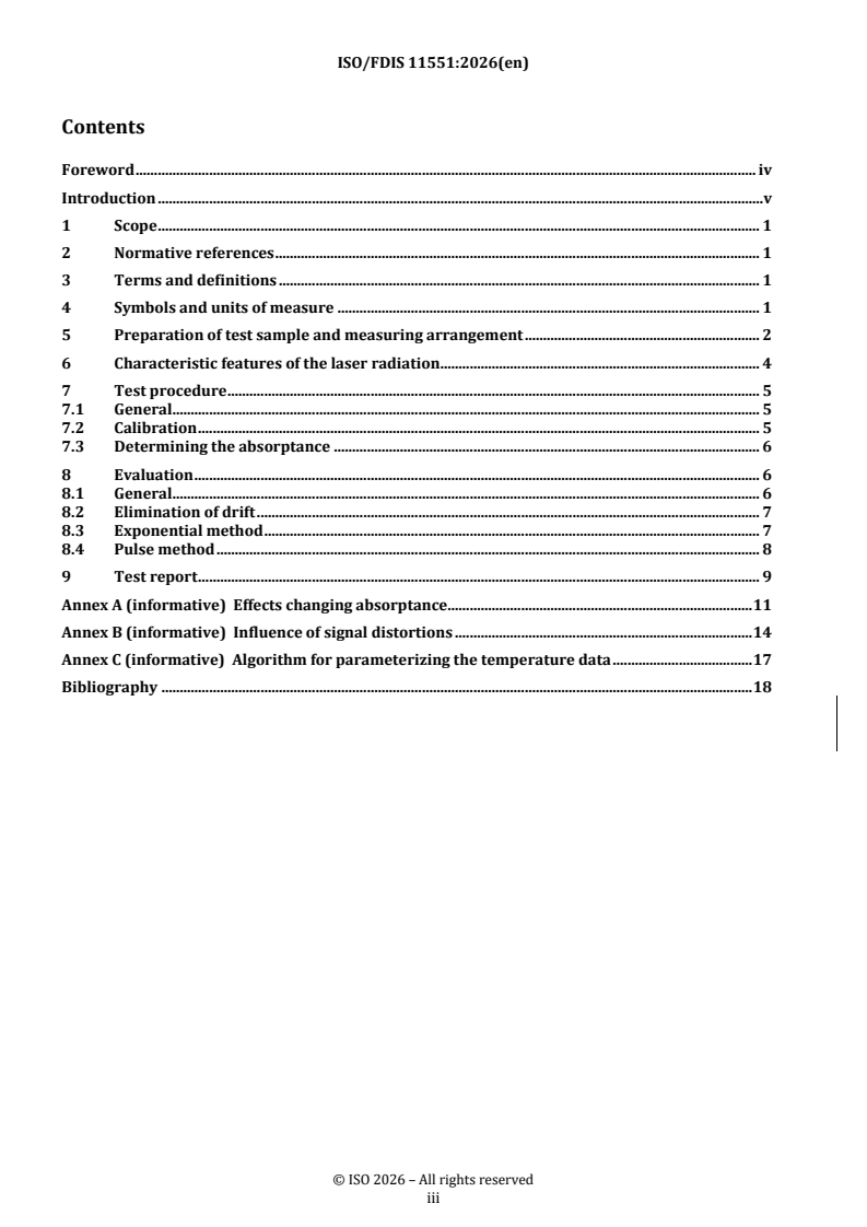
Contents Page
Foreword .iv
Introduction .v
1 Scope . 1
2 Normative references . 1
3 Terms and definitions . 1
4 Symbols and units of measure . 1
5 Preparation of test sample and measuring arrangement . 2
6 Characteristic features of the laser radiation . 4
7 Test procedure . 5
7.1 General .5
7.2 Calibration .5
7.2.1 Calibration of the radiant power signal .5
7.2.2 Calibration of the temperature signal .5
7.2.3 Calibration of the thermal response .5
7.2.4 Measurement of the background signal .6
7.3 Determining the absorptance .6
8 Evaluation . 6
8.1 General .6
8.2 Elimination of drift .7
8.3 Exponential method .7
8.4 Pulse method .8
9 Test report . 9
Annex A (informative) Effects changing absorptance .11
Annex B (informative) Influence of signal distortions . 14
Annex C (informative) Algorithm for parameterizing the temperature data . 17
Bibliography .18
iii
Foreword
ISO (the International Organization for Standardization) is a worldwide federation of national standards
bodies (ISO member bodies). The work of preparing International Standards is normally carried out through
ISO technical committees. Each member body interested in a subject for which a technical committee
has been established has the right to be represented on that committee. International organizations,
governmental and non-governmental, in liaison with ISO, also take part in the work. ISO collaborates closely
with the International Electrotechnical Commission (IEC) on all matters of electrotechnical standardization.
The procedures used to develop this document and those intended for its further maintenance are described
in the ISO/IEC Directives, Part 1. In particular, the different approval criteria needed for the different types
of ISO documents should be noted. This document was drafted in accordance with the editorial rules of the
ISO/IEC Directives, Part 2 (see www.iso.org/directives).
ISO draws attention to the possibility that the implementation of this document may involve the use of (a)
patent(s). ISO takes no position concerning the evidence, validity or applicability of any claimed patent
rights in respect thereof. As of the date of publication of this document, ISO had not received notice of (a)
patent(s) which may be required to implement this document. However, implementers are cautioned that
this may not represent the latest information, which may be obtained from the patent database available at
www.iso.org/patents. ISO shall not be held responsible for identifying any or all such patent rights.
Any trade name used in this document is information given for the convenience of users and does not
constitute an endorsement.
For an explanation of the voluntary nature of standards, the meaning of ISO specific terms and expressions
related to conformity assessment, as well as information about ISO's adherence to the World Trade
Organization (WTO) principles in the Technical Barriers to Trade (TBT), see www.iso.org/iso/foreword.html.
This document was prepared by Technical Committee 172, Optics and Photonics, Subcommittee SC 9, Laser
and electro-optical systems, in collaboration with the European Committee for Standardization (CEN)
Technical Committee CEN/TC 123, Lasers and Photonics, in accordance with the Agreement on technical
cooperation between ISO and CEN (Vienna Agreement).
This fourth edition cancels and replaces the third edition (ISO 11551:2019), which has been technically
revised.
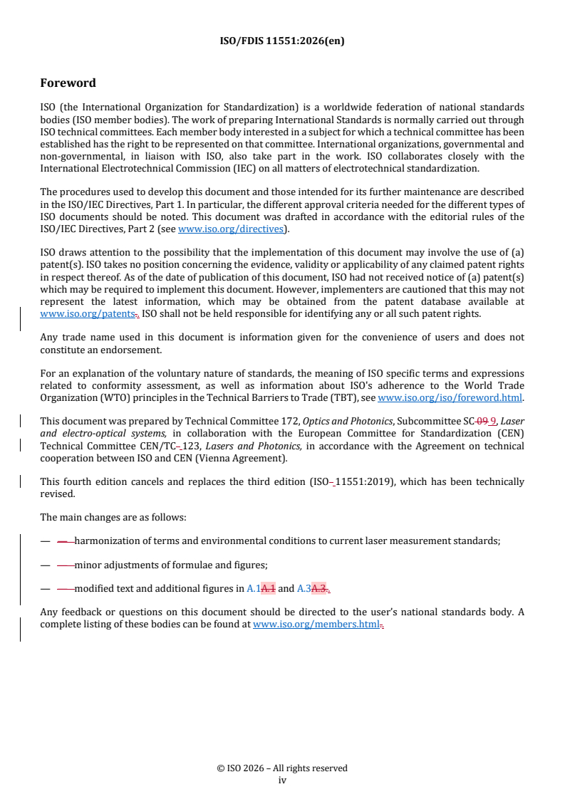
The main changes are as follows:
— harmonization of terms and environmental conditions to current laser measurement standards;
— minor adjustments of formulae and figures;
— modified text and additional figures in A.1 and A.3.
Any feedback or questions on this document should be directed to the user’s national standards body. A
complete listing of these bodies can be found at www.iso.org/members.html.
iv
Introduction
To characterize an optical component, it is important to know its absorptance. When radiation impinges
upon a component, a part of that radiation is absorbed, increasing the temperature of the component. In this
document only the part of the absorbed radiant power/energy, that is converted into heat, is measured. If
enough radiant energy is absorbed, the optical properties of the component can change, and the component
can even be destroyed. Absorptance is the ratio of the radiant flux absorbed to the radiant flux of the incident
radiation.
In the procedures described in this document, the absorptance is determined calorimetrically as the ratio
of radiant power or radiant energy absorbed by the component to the total radiant power or radiant energy,
respectively, impinging upon the component. The assumption is made that the absorptance of the test sample
is constant within the temperature fluctuations experienced by the component during the measurement.
v
FINAL DRAFT International Standard ISO/FDIS 11551:2026(en)
Optics and photonics — Lasers and laser-related equipment
— Test method for absorptance of optical laser components
WARNING — Laser calorimetric measurements may involve high power lasers, the use of which
may come with significant risks, which may include, but are not limited to; eye injury to people;
laser burns to people or equipment; ignition of materials; generating debris of toxic materials in
the substrate or coating; electrical hazards. It is the responsibility of the user to comply with local
guidelines and regulations for their particular set-up.
1 Scope
This document specifies procedures and techniques for obtaining comparable values for the absorptance of
optical laser components.
2 Normative references
The following documents are referred to in the text in such a way that some or all of their content constitutes
requirements of this document. For dated references, only the edition cited applies. For undated references,
the latest edition of the referenced document (including any amendments) applies.
ISO 11145, Optics and photonics — Lasers and laser-related equipment — Vocabulary and symbols
ISO 14644-1, Cleanrooms and associated controlled environments — Part 1: Classification of air cleanliness by
particle concentration
ISO 80000-7, Quantities and units — Part 7: Light and radiation
3 Terms and definitions
For the purposes of this document, the terms and definitions given in ISO 11145 and ISO 80000-7 and the
following apply.
ISO and IEC maintain terminology databases for use in standardization at the following addresses:
— ISO Online browsing platform: available at https:// www .iso .org/ obp
— IEC Electropedia: available at https:// www .electropedia .org/
3.1
absorptance
a
ratio of the radiant flux absorbed to the radiant flux of the incident radiation
Note 1 to entry: The definition of absorptance used for this document is limited to absorptance processes which convert
the absorbed radiant energy to heat. For certain types of optics and radiation, additional non-thermal processes can
result in absorption losses which will not be detected by the test procedure described here (see Annex A).
4 Symbols and units of measure
The symbols and units of measurement used are the following:
Table 1 — Symbols and units of measure
Symbol Term Unit
Thermal capacity of test sample, holder, etc. J/K
Ceff
c Specific heat capacity of test sample J/(kg·K)
p
d , d Beam width on test sample mm
σx σy
m Mass of test sample, holder, etc. kg
i
P cw radiant power W
P Average laser power for continuous pulse mode operation W
av
Typical peak radiant power for repetitive pulse mode oper-
P W
pk
ation
t Duration of irradiation s
B
t Duration of cooling s
C
t Duration of drift s
D
Δt Time interval s
T Ambient temperature K
amb
ΔT Temperature difference K
a Absorptance 1
β Angle of incidence Rad
γ Thermal loss coefficient 1/s
λ Wavelength nm
κ Heat conductivity W/(m·K)
η Mass density kg/m
σ Error sum —
min
Q Heat source W/m
5 Preparation of test sample and measuring arrangement
Storage, cleaning and the preparation of the test samples are carried out in accordance with the
manufacturer’s instructions for normal use.
The environment of the testing place shall be adapted to the application and test wavelength. It should consist
of dust-free filtered air with relative humidity between 40 % and 60 %. The residual dust shall be reduced in
accordance with cleanroom class 7 as defined in ISO 14644-1. However, some specific spectral ranges might
could require nitrogen purged environments (deep UV) or zero humidity (several IR wavelengths). Nitrogen
quality for the deep UV range should be at 99,999 % or higher. If these conditions cannot be supplied,
absorption within the surrounding atmosphere will be included in the test result. An environment free from
draughts is very important in order to keep thermal disturbances and heat loss by convection as small as
possible. Measurements in ambient atmosphere and vacuum can have different influences on the measured
absorptance.
A laser shall be used as the radiation source. To keep errors as low as possible, the laser power chosen
for measurements is as high as possible but without causing any deterioration to the component. At high
irradiance, it shall be ensured that the sample is not damaged. This shall be ensured by the fact that the
measurement shall be reproducible within the specified error limits.
Wavelength, angle of incidence and state of polarization of the laser radiation used for the measurement
shall correspond to the values specified by the manufacturer for the use of the test sample. If also ranges
are accepted for these three quantities, any combination of wavelength, angle of incidence and state of
polarization may be chosen from those ranges. The absorption of an optical component can depend on
further parameters, e.g. irradiance or irradiation dose. In such cases, the measurement sequence should be
chosen individually. For more details, refer to Annex A.
The test sample is mounted in a suitable holder. It is preferable to mount the sample in a manner that
minimizes any thermal contact between the sample and the holder. In this arrangement, the thermal sensor
is attached directly to the sample surface. Reproducible thermal contact between the thermal sensor and the
sample surface is important. Also, care should be taken to maintain constant thermal impedance between
the sample and the holder. Accurate calibration is critically dependent on the location of the thermal sensor,
on the material the sample is made of, and on the sample geometry. Refer to Annex B for a detailed discussion
of these considerations.
It can be difficult to attach the thermal sensor to a small test sample or a sample having an irregular shape.
Such a sample is mounted to the holder in a manner that maximizes thermal contact between the sample
and the holder, while the thermal sensor is attached to or integrated into the holder. Reproducible thermal
contact between the thermal sensor and the holder is important. Also, care should be taken to maintain
constant thermal conductance between the sample and the holder.
In order to increase the precision of the measurements, the sample should be mounted inside a chamber
designed for thermal shielding, with apertures for the laser beam. Special attention shall be given to ensure
that the temperature measurement itself does not cause a change of the sample temperature.
Suitable diaphragms should be placed in the beam path in front of and behind the test sample to ensure
that only the test sample is irradiated by the measuring beam and that reflected or stray radiation will
not strike the holder or the chamber walls. The number of transmissive optics employed for beam guiding
should be minimized in order to reduce possible distortions by multi-reflections or scattered radiation. The
transmitted and reflected partial beams shall be directed on to beam dumps with minimized back scatter.
Figure 1 shows a schematic measuring arrangement. The curved folding mirror M1 is recommended for
imaging the laser output window on to the sample in order to avoid diffracted radiation influencing the
measurement.
Key
1 laser
2 mirror M1
3 optical axis
4 mirror M2
5 test chamber
6 sample holder
7 test sample
8 personal computer
9 beam stop
10 thermal sensor
11 control unit
12 radiant power detector
Figure 1 — Typical arrangement for measurement of the absorptance
6 Characteristic features of the laser radiation
The following physical quantities are needed for characterizing the laser radiation used for the test:
— wavelength, λ;
— angle of incidence, β;
— state and degree of polarization;
— beam widths on the test sample, d , d ;
σx σy
— average radiant power, P , for cw or continuously pulsed lasers;
av
— typical peak radiant power, P , and pulse energy, Q, in the case of pulsed lasers;
pk
— duration of irradiation, t .
B
7 Test procedure
7.1 General
The following auxiliary tests shall be performed on a regular basis and whenever the measuring arrangement
has been altered.
7.2 Calibration
7.2.1 Calibration of the radiant power signal
Calibrate the radiant power signal by placing a calibrated laser power detector at the location of the test
components and, in order to obtain correct calibration, compare the measured laser power to the signal of
the power monitor used during absorptance tests.
7.2.2 Calibration of the temperature signal
Calibrate the temperature signal by fixing a test sample, to which a calibrated thermal sensor is attached, to
the sample holder. Compare the temperature signals of this calibrated sensor and the sensors used during
absorptance tests while varying the ambient temperature slowly over the linearity range of the temperature
detectors at the typical test temperature.
7.2.3 Calibration of the thermal response
For certain types of sample materials and geometries, the temperature rise induced by the absorbed heat
can differ from the theoretical response expected for ideal materials having infinite thermal conductivity.
In these cases, a correction factor, f , shall be determined, which compensates for the influence of such
c
phenomena on the absorptance test result. f is unity if the influence of limited thermal conductivity can
c
be neglected. In order to derive a correct value for f , the heating scheme of the calibration routine needs to
c
be consistent with the heating characteristic of the samples to be tested. Surface absorbers shall be related
to a correction factor derived from a calibration based on surface heating. And a bulk absorber shall be
corrected with a bulk heated calibration sample.
For calibration, a reference sample of known absorptance, which is identical to the samples under
investigation with respect to substrate geometry and thermal diffusivity, is tested for absorptance as in
Annex B. The irradiation time and evaluation method used for calibration shall be the same as for the sample
under test.
Depending on the evaluation method used for the absorptance test, the correction coefficient can be
calculated by substituting the value of the known calibration sample absorptance for a in Formula (2) (see
8.3) or Formula (5) (see 8.4), and solving for f .
c
A known absorptance can be achieved by applying a thin,
...
ISO/TC 172/SC 09 9
Secretariat: DIN
Date: 2026-04-08xx
Optics and photonics — Lasers and laser-related equipment — Test
method for absorptance of optical laser components
Optique et photonique — Lasers et équipements associés aux lasers — Méthode d'essai du facteur d'absorption
des composants optiques pour lasers
FDIS stage
TThhiis drs draafftt i is s susubbmmiitttteed d ttoo aa ppaarraallellel l vvoottee i inn IISSOO,, CCEEN.N.
All rights reserved. Unless otherwise specified, or required in the context of its implementation, no part of this publication
may be reproduced or utilized otherwise in any form or by any means, electronic or mechanical, including photocopying,
or posting on the internet or an intranet, without prior written permission. Permission can be requested from either ISO
at the address below or ISO’s member body in the country of the requester.
ISO copyright office
CP 401 • Ch. de Blandonnet 8
CH-1214 Vernier, Geneva
Phone: + 41 22 749 01 11
EmailE-mail: copyright@iso.org
Website: www.iso.org
Published in Switzerland
ii
Contents
Foreword . iv
Introduction . v
1 Scope . 1
2 Normative references . 1
3 Terms and definitions . 1
4 Symbols and units of measure . 1
5 Preparation of test sample and measuring arrangement . 2
6 Characteristic features of the laser radiation . 4
7 Test procedure . 5
7.1 General . 5
7.2 Calibration . 5
7.3 Determining the absorptance . 6
8 Evaluation . 6
8.1 General . 6
8.2 Elimination of drift . 7
8.3 Exponential method . 7
8.4 Pulse method . 8
9 Test report . 9
Annex A (informative) Effects changing absorptance . 11
Annex B (informative) Influence of signal distortions . 14
Annex C (informative) Algorithm for parameterizing the temperature data . 17
Bibliography . 18
iii
Foreword
ISO (the International Organization for Standardization) is a worldwide federation of national standards
bodies (ISO member bodies). The work of preparing International Standards is normally carried out through
ISO technical committees. Each member body interested in a subject for which a technical committee has been
established has the right to be represented on that committee. International organizations, governmental and
non-governmental, in liaison with ISO, also take part in the work. ISO collaborates closely with the
International Electrotechnical Commission (IEC) on all matters of electrotechnical standardization.
The procedures used to develop this document and those intended for its further maintenance are described
in the ISO/IEC Directives, Part 1. In particular, the different approval criteria needed for the different types of
ISO documents should be noted. This document was drafted in accordance with the editorial rules of the
ISO/IEC Directives, Part 2 (see www.iso.org/directives).
ISO draws attention to the possibility that the implementation of this document may involve the use of (a)
patent(s). ISO takes no position concerning the evidence, validity or applicability of any claimed patent rights
in respect thereof. As of the date of publication of this document, ISO had not received notice of (a) patent(s)
which may be required to implement this document. However, implementers are cautioned that this may not
represent the latest information, which may be obtained from the patent database available at
www.iso.org/patents. ISO shall not be held responsible for identifying any or all such patent rights.
Any trade name used in this document is information given for the convenience of users and does not
constitute an endorsement.
For an explanation of the voluntary nature of standards, the meaning of ISO specific terms and expressions
related to conformity assessment, as well as information about ISO's adherence to the World Trade
Organization (WTO) principles in the Technical Barriers to Trade (TBT), see www.iso.org/iso/foreword.html.
This document was prepared by Technical Committee 172, Optics and Photonics, Subcommittee SC 09 9, Laser
and electro-optical systems, in collaboration with the European Committee for Standardization (CEN)
Technical Committee CEN/TC 123, Lasers and Photonics, in accordance with the Agreement on technical
cooperation between ISO and CEN (Vienna Agreement).
This fourth edition cancels and replaces the third edition (ISO 11551:2019), which has been technically
revised.
The main changes are as follows:
— — harmonization of terms and environmental conditions to current laser measurement standards;
— — minor adjustments of formulae and figures;
— — modified text and additional figures in A.1A.1 and A.3A.3.
Any feedback or questions on this document should be directed to the user’s national standards body. A
complete listing of these bodies can be found at www.iso.org/members.html.
iv
Introduction
To characterize an optical component, it is important to know its absorptance. When radiation impinges upon
a component, a part of that radiation is absorbed, increasing the temperature of the component. In this
document only the part of the absorbed radiant power/energy, that is converted into heat, is measured. If
enough radiant energy is absorbed, the optical properties of the component can change, and the component
can even be destroyed. Absorptance is the ratio of the radiant flux absorbed to the radiant flux of the incident
radiation.
In the procedures described in this document, the absorptance is determined calorimetrically as the ratio of
radiant power or radiant energy absorbed by the component to the total radiant power or radiant energy,
respectively, impinging upon the component. The assumption is made that the absorptance of the test sample
is constant within the temperature fluctuations experienced by the component during the measurement.
v
Optics and photonics — Lasers and laser-related equipment — Test
method for absorptance of optical laser components
WARNING — Laser calorimetric measurements may involve high power lasers, the use of which may
come with significant risks, which may include, but are not limited to; eye injury to people; laser burns
to people or equipment; ignition of materials; generating debris of toxic materials in the substrate or
coating; electrical hazards. It is the responsibility of the user to comply with local guidelines and
regulations for their particular set-up.
1 Scope
This document specifies procedures and techniques for obtaining comparable values for the absorptance of
optical laser components.
2 Normative references
The following documents are referred to in the text in such a way that some or all of their content constitutes
requirements of this document. For dated references, only the edition cited applies. For undated references,
the latest edition of the referenced document (including any amendments) applies.
ISO 11145, Optics and photonics — Lasers and laser-related equipment — Vocabulary and symbols
ISO 14644--1, Cleanrooms and associated controlled environments — Part 1: Classification of air cleanliness by
particle concentration
ISO 80000--7, Quantities and units — Part 7: Light and radiation
3 Terms and definitions
For the purposes of this document, the terms and definitions given in ISO 11145 and ISO 80000-7 and the
following apply.
ISO and IEC maintain terminology databases for use in standardization at the following addresses:
— — ISO Online browsing platform: available at https://www.iso.org/obp
— — IEC Electropedia: available at https://www.electropedia.org/
3.1 3.1
absorptance
a
ratio of the radiant flux absorbed to the radiant flux of the incident radiation
Note 1 to entry: The definition of absorptance used for this document is limited to absorptance processes which convert
the absorbed radiant energy to heat. For certain types of optics and radiation, additional non-thermal processes can
result in absorption losses which will not be detected by the test procedure described here (see Annex AAnnex A).).
4 Symbols and units of measure
The symbols and units of measurement used are the following:
Table 1 — Symbols and units of measure
Symbol Term Unit
Ceff Thermal capacity of test sample, holder, etc. J/K
cp Specific heat capacity of test sample J/(kg·K)
d , d Beam width on test sample mm
σx σy
mi Mass of test sample, holder, etc. kg
P cw radiant power W
Pav Average laser power for continuous pulse mode operation W
Typical peak radiant power for repetitive pulse mode
P W
pk
operation
tB Duration of irradiation s
tC Duration of cooling s
t Duration of drift s
D
Δt Time interval s
T Ambient temperature K
amb
ΔT Temperature difference K
a Absorptance 1
β Angle of incidence Rad
γ Thermal loss coefficient 1/s
λ Wavelength nm
κ Heat conductivity W/(m·K)
η Mass density kg/m
σ Error sum -—
min
Q Heat source W/m
5 Preparation of test sample and measuring arrangement
Storage, cleaning and the preparation of the test samples are carried out in accordance with the
manufacturer’s instructions for normal use.
The environment of the testing place shall be adapted to the application and test wavelength. It should consist
of dust-free filtered air with relative humidity between 40 % and 60 %. The residual dust shall be reduced in
accordance with cleanroom class 7 as defined in ISO 14644-1. However, some specific spectral ranges might
could require nitrogen purged environments (deep UV) or zero humidity (several IR wavelengths). Nitrogen
quality for the deep UV range should be at 99,999 % or higher. If these conditions cannot be supplied,
absorption within the surrounding atmosphere will be included in the test result. An environment free from
draughts is very important in order to keep thermal disturbances and heat loss by convection as small as
possible. Measurements in ambient atmosphere and vacuum can have different influences on the measured
absorptance.
A laser shall be used as the radiation source. To keep errors as low as possible, the laser power chosen for
measurements is as high as possible but without causing any deterioration to the component. At high
irradiance, it shall be ensured that the sample is not damaged. This shall be ensured by the fact that the
measurement shall be reproducible within the specified error limits.
Wavelength, angle of incidence and state of polarization of the laser radiation used for the measurement shall
correspond to the values specified by the manufacturer for the use of the test sample. If also ranges are
accepted for these three quantities, any combination of wavelength, angle of incidence and state of
polarization may be chosen from those ranges. The absorption of an optical component can depend on further
parameters, e.g. irradiance or irradiation dose. In such cases, the measurement sequence should be chosen
individually. For more details, refer to Annex AAnnex A.
The test sample is mounted in a suitable holder. It is preferable to mount the sample in a manner that
minimizes any thermal contact between the sample and the holder. In this arrangement, the thermal sensor is
attached directly to the sample surface. Reproducible thermal contact between the thermal sensor and the
sample surface is important. Also, care should be taken to maintain constant thermal impedance between the
sample and the holder. Accurate calibration is critically dependent on the location of the thermal sensor, on
the material the sample is made of, and on the sample geometry. Refer to Annex BAnnex B for a detailed
discussion of these considerations.
It can be difficult to attach the thermal sensor to a small test sample or a sample having an irregular shape.
Such a sample is mounted to the holder in a manner that maximizes thermal contact between the sample and
the holder, while the thermal sensor is attached to or integrated into the holder. Reproducible thermal contact
between the thermal sensor and the holder is important. Also, care should be taken to maintain constant
thermal conductance between the sample and the holder.
In order to increase the precision of the measurements, the sample should be mounted inside a chamber
designed for thermal shielding, with apertures for the laser beam. Special attention shall be given to ensure
that the temperature measurement itself does not cause a change of the sample temperature.
Suitable diaphragms should be placed in the beam path in front of and behind the test sample to ensure that
only the test sample is irradiated by the measuring beam and that reflected or stray radiation will not strike
the holder or the chamber walls. The number of transmissive optics employed for beam guiding should be
minimized in order to reduce possible distortions by multi-reflections or scattered radiation. The transmitted
and reflected partial beams shall be directed on to beam dumps with minimized back scatter.
Figure 1Figure 1 shows a schematic measuring arrangement. The curved folding mirror M1 is recommended
for imaging the laser output window on to the sample in order to avoid diffracted radiation influencing the
measurement.
11551_ed4fig1.EPS
Key
1 laser
2 mirror M1
3 optical axis
4 mirror M2
5 test chamber
6 sample holder
7 test sample
8 personal computer
9 beam stop
10 thermal sensor
11 control unit
12 radiant power detector
Figure 1 — Typical arrangement for measurement of the absorptance
6 Characteristic features of the laser radiation
The following physical quantities are needed for characterizing the laser radiation used for the test:
— — wavelength, λ;
— — angle of incidence, β;
— — state and degree of polarization;
— — beam widths on the test sample, d , d ;
σx σy
— — average radiant power, P , for cw or continuously pulsed lasers;
av
— — typical peak radiant power, P , and pulse energy, Q, in the case of pulsed lasers;
pk
— — duration of irradiation, t .
B
7 Test procedure
7.1 General
The following auxiliary tests shall be performed on a regular basis and whenever the measuring arrangement
has been altered.
7.2 Calibration
7.2.1 Calibration of the radiant power signal
Calibrate the radiant power signal by placing a calibrated laser power detector at the location of the test
components and, in order to obtain correct calibration, compare the measured laser power to the signal of the
power monitor used during absorptance tests.
7.2.2 Calibration of the temperature signal
Calibrate the temperature signal by fixing a test sample, to which a calibrated thermal sensor is attached, to
the sample holder. Compare the temperature signals of this calibrated sensor and the sensors used during
absorptance tests while varying the ambient temperature slowly over the linearity range of the temperature
detectors at the typical test temperature.
7.2.3 Calibration of the thermal response
For certain types of sample materials and geometries, the temperature rise induced by the absorbed heat can
differ from the theoretical response expected for ideal materials having infinite thermal conductivity. In these
cases, a correction factor, f , shall be determined, which compensates for the influence of such phenomena on
c
the absorptance test result. f is unity if the influence of limited thermal conductivity can be neglected. In order
c
to derive a correct value for f , the heating scheme of the calibration routine needs to be consistent with the
c
heating characteristic of the samples to be tested. Surface absorbers shall be related to a correction factor
derived from a calibration based on surface heating. And a bulk absorber shall be corrected with a bulk heated
calibration sample.
For calibration, a reference sample of known absorptance, which is identical to the samples under
investigation with respect to substrate geometry and thermal diffusivity, is tested for absorptance as in
Annex BAnnex B. The irradiation time and evaluation method used for calibration shall be the same as for the
sample under test.
Depending on the evaluation method used for the absorptance test, the correction coefficient can be calculated
by substituting the value of the known calibration sample absorptance for a in Formula (2)Formula (2) (see
8.38.3)) or Formula (5)Formula (5) (see 8.48.4),), and solving for f .
c
A known absorptance can be achieved by applying a thin, high-absorbing coating to the sample surface area
that is exposed to irradiation. High absorptance values can be determined with sufficient accuracy, e.g. by
measuring the fraction of transmitted, reflected and scattered radiation. For absorptance testing of samples
with high absorptance values, the laser power should be suitably attenuated in order to avoid damage to the
samples and to ensure that the resulting temperature rise is in the same order of magnitude as the
temperature which is achieved for typical measurements. This procedure applies only for samples of high
surface absorption, where bulk absorption can be neglected.
As an alternative to irradiating a calibration sample of known absorptance with the laser beam, the thermal
energy may be deposited electrically in the test sample by attaching an electric resistor to the tested surface.
The absorbed electrical power is given by RI , where R is the electrical resistance and I is the electric current
during “irradiation”. Care should be taken to ensure good thermal contact between resistor and sample.
Furthermore, especially in the case of samples with low thermal conductivity, the area of the resistor should
match the area irradiated by the laser beam under normal test conditions. This procedure can in principle be
applied to both, surface and bulk absorbing samples. Care should be taken to ensure that the heating scheme
of the calibration sample is close or identical to the expected heating scheme of the test samples.
7.2.4 Measurement of the background signal
For maximum accuracy and suppression of possible signal distortions, the imaging and alignment of the laser
beam shall be optimized. A measurement with an empty holder or with an absorptance-free component can
be used to verify that the measuring arrangement is not influenced by reflected or stray radiation. The
amplitude of the temperature fluctuations during the test interval shall be at least one order of magnitude
below t
...
PROJET FINAL
Norme
internationale
ISO/TC 172/SC 9
Optique et photonique — Lasers et
Secrétariat: DIN
équipements associés aux lasers
Début de vote:
— Méthode d'essai du facteur
2026-05-26
d'absorption des composants
Vote clos le:
optiques pour lasers
2026-07-21
Optics and photonics — Lasers and laser-related equipment —
Test method for absorptance of optical laser components
LES DESTINATAIRES DU PRÉSENT PROJET SONT
INVITÉS À PRÉSENTER, AVEC LEURS OBSERVATIONS,
NOTIFICATION DES DROITS DE PROPRIÉTÉ DONT ILS
AURAIENT ÉVENTUELLEMENT CONNAISSANCE ET À
FOURNIR UNE DOCUMENTATION EXPLICATIVE.
OUTRE LE FAIT D’ÊTRE EXAMINÉS POUR
ÉTABLIR S’ILS SONT ACCEPTABLES À DES FINS
INDUSTRIELLES, TECHNOLOGIQUES ET COM-MERCIALES,
AINSI QUE DU POINT DE VUE DES UTILISATEURS, LES
PROJETS DE NORMES
TRAITEMENT PARALLÈLE ISO/CEN
INTERNATIONALES DOIVENT PARFOIS ÊTRE CONSIDÉRÉS
DU POINT DE VUE DE LEUR POSSI BILITÉ DE DEVENIR DES
NORMES POUVANT
SERVIR DE RÉFÉRENCE DANS LA RÉGLEMENTATION
NATIONALE.
Numéro de référence
PROJET FINAL
Norme
internationale
ISO/TC 172/SC 9
Optique et photonique — Lasers et
Secrétariat: DIN
équipements associés aux lasers
Début de vote:
— Méthode d'essai du facteur
2026-05-26
d'absorption des composants
Vote clos le:
optiques pour lasers
2026-07-21
Optics and photonics — Lasers and laser-related equipment —
Test method for absorptance of optical laser components
LES DESTINATAIRES DU PRÉSENT PROJET SONT
INVITÉS À PRÉSENTER, AVEC LEURS OBSERVATIONS,
NOTIFICATION DES DROITS DE PROPRIÉTÉ DONT ILS
AURAIENT ÉVENTUELLEMENT CONNAISSANCE ET À
FOURNIR UNE DOCUMENTATION EXPLICATIVE.
DOCUMENT PROTÉGÉ PAR COPYRIGHT
OUTRE LE FAIT D’ÊTRE EXAMINÉS POUR
ÉTABLIR S’ILS SONT ACCEPTABLES À DES FINS
© ISO 2026 INDUSTRIELLES, TECHNOLOGIQUES ET COM-MERCIALES,
AINSI QUE DU POINT DE VUE DES UTILISATEURS, LES
Tous droits réservés. Sauf prescription différente ou nécessité dans le contexte de sa mise en œuvre, aucune partie de cette
PROJETS DE NORMES
TRAITEMENT PARALLÈLE ISO/CEN
INTERNATIONALES DOIVENT PARFOIS ÊTRE CONSIDÉRÉS
publication ne peut être reproduite ni utilisée sous quelque forme que ce soit et par aucun procédé, électronique ou mécanique,
DU POINT DE VUE DE LEUR POSSI BILITÉ DE DEVENIR DES
y compris la photocopie, ou la diffusion sur l’internet ou sur un intranet, sans autorisation écrite préalable. Une autorisation peut
NORMES POUVANT
être demandée à l’ISO à l’adresse ci-après ou au comité membre de l’ISO dans le pays du demandeur.
SERVIR DE RÉFÉRENCE DANS LA RÉGLEMENTATION
NATIONALE.
ISO copyright office
Case postale 401 • Ch. de Blandonnet 8
CH-1214 Vernier, Genève
Tél.: +41 22 749 01 11
E-mail: copyright@iso.org
Web: www.iso.org
Publié en Suisse Numéro de référence
ii
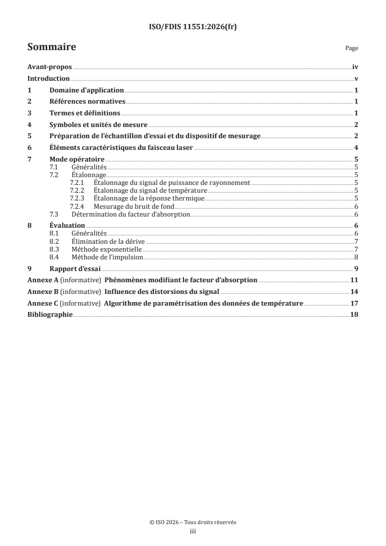
Sommaire Page
Avant-propos .iv
Introduction .v
1 Domaine d'application . 1
2 Références normatives . 1
3 Termes et définitions . 1
4 Symboles et unités de mesure . 2
5 Préparation de l’échantillon d’essai et du dispositif de mesurage . 2
6 Éléments caractéristiques du faisceau laser . 4
7 Mode opératoire . 5
7.1 Généralités .5
7.2 Étalonnage .5
7.2.1 Étalonnage du signal de puissance de rayonnement .5
7.2.2 Étalonnage du signal de température .5
7.2.3 Étalonnage de la réponse thermique .5
7.2.4 Mesurage du bruit de fond .6
7.3 Détermination du facteur d’absorption .6
8 Évaluation . 6
8.1 Généralités .6
8.2 Élimination de la dérive .7
8.3 Méthode exponentielle .7
8.4 Méthode de l’impulsion .8
9 Rapport d’essai . 9
Annexe A (informative) Phénomènes modifiant le facteur d’absorption .11
Annexe B (informative) Influence des distorsions du signal . 14
Annexe C (informative) Algorithme de paramétrisation des données de température . 17
Bibliographie .18
iii
Avant-propos
L'ISO (Organisation internationale de normalisation) est une fédération mondiale d'organismes nationaux
de normalisation (comités membres de l'ISO). L'élaboration des Normes internationales est en général
confiée aux comités techniques de l'ISO. Chaque comité membre intéressé par une étude a le droit de faire
partie du comité technique créé à cet effet. Les organisations internationales, gouvernementales et non
gouvernementales, en liaison avec l'ISO participent également aux travaux. L'ISO collabore étroitement avec
la Commission électrotechnique internationale (IEC) en ce qui concerne la normalisation électrotechnique.
Les procédures utilisées pour élaborer le présent document et celles destinées à sa mise à jour sont
décrites dans les Directives ISO/IEC, Partie 1. Il convient, en particulier, de prendre note des différents
critères d'approbation requis pour les différents types de documents ISO. Le présent document a
été rédigé conformément aux règles de rédaction données dans les Directives ISO/IEC, Partie 2 (voir
www.iso.org/directives).
L’ISO attire l’attention sur le fait que la mise en application du présent document peut entraîner l’utilisation
d’un ou de plusieurs brevets. L’ISO ne prend pas position quant à la preuve, à la validité et à l’applicabilité de
tout droit de propriété revendiqué à cet égard. À la date de publication du présent document, l’ISO n'avait pas
reçu notification qu’un ou plusieurs brevets pouvaient être nécessaires à sa mise en application. Toutefois,
il y a lieu d’avertir les responsables de la mise en application du présent document que des informations
plus récentes sont susceptibles de figurer dans la base de données de brevets, disponible à l'adresse
www.iso.org/brevets. L’ISO ne saurait être tenue pour responsable de ne pas avoir identifié tout ou partie de
tels droits de propriété.
Les appellations commerciales éventuellement mentionnées dans le présent document sont données pour
information, par souci de commodité, à l’intention des utilisateurs et ne sauraient constituer un engagement.
Pour une explication de la nature volontaire des normes, la signification des termes et expressions
spécifiques de l'ISO liés à l'évaluation de la conformité, ou pour toute information au sujet de l'adhésion de
l'ISO aux principes de l’Organisation mondiale du commerce (OMC) concernant les obstacles techniques au
commerce (OTC), voir www.iso.org/avant-propos.
Le présent document a été élaboré par le comité technique ISO/TC 172, Optique et photonique, Sous-comité
SC 9, Lasers et systèmes électro-optiques en collaboration avec le Comité européen de normalisation (CEN)
comité technique CEN/TC 123 Lasers et photonique, conformément à l’Accord de coopération technique entre
l’ISO et le CEN (Accord de Vienne).
Cette quatrième édition annule et remplace la troisième édition (ISO 11551:2019), qui a fait l’objet d’une
révision technique.
Les principales modifications sont les suivantes:
— harmonisation des termes et des conditions environnementales avec les normes actuelles de mesure
laser;
— ajustements mineurs des formules et des figures;
— texte modifié et figures ajoutées en A.1 et A.3.
Il convient que l’utilisateur adresse tout retour d’information ou toute question concernant le présent
document à l’organisme national de normalisation de son pays. Une liste exhaustive desdits organismes se
trouve à l’adresse www.iso.org/members.html.
iv
Introduction
Pour caractériser un composant optique, il est important de connaître son facteur d’absorption. Lorsque le
rayonnement atteint un composant optique, une partie de ce rayonnement est absorbée, ce qui augmente
la température de ce composant. Dans le présent document, seule la partie de la puissance/énergie de
rayonnement absorbée, qui est convertie en chaleur, est mesurée. Si une quantité suffisante d’énergie de
rayonnement est absorbée, les propriétés optiques du composant peuvent changer et ce dernier risque
même d’être détruit. Le facteur d’absorption est le rapport du flux énergétique absorbé au flux énergétique
du rayonnement incident.
Dans les modes opératoires décrits dans le présent document, le facteur d’absorption est déterminé par
calorimétrie comme étant le rapport de la puissance de rayonnement ou de l’énergie de rayonnement absorbée
par le composant à la puissance de rayonnement ou à l’énergie de rayonnement totale, respectivement,
atteignant le composant en question. Il est supposé que le facteur d’absorption de l’échantillon d’essai reste
constant dans la plage de variation de température à laquelle est soumis le composant au cours du mesurage.
v
PROJET FINAL Norme internationale ISO/FDIS 11551:2026(fr)
Optique et photonique — Lasers et équipements associés
aux lasers — Méthode d'essai du facteur d'absorption des
composants optiques pour lasers
AVERTISSEMENT — Les mesures calorimétriques au laser peuvent impliquer des lasers de haute
puissance, dont l’utilisation peut comporter des risques importants, notamment, sans être limité à,
des blessures oculaires aux personnes, des brûlures au laser sur des personnes ou sur du matériel,
l’inflammation de matériaux, la formation de débris de matières toxiques dans le substrat ou le
revêtement, des risques électriques. Il incombe à l’utilisateur de se conformer aux lignes directrices
et règlementations locales pour sa configuration particulière.
1 Domaine d'application
Le présent document spécifie les modes opératoires et les techniques utilisés pour obtenir des valeurs
comparables du facteur d’absorption des composants optiques pour lasers.
2 Références normatives
Les documents suivants cités dans le texte constituent, pour tout ou partie de leur contenu, des exigences du
présent document. Pour les références datées, seule l’édition citée s’applique. Pour les références non datées,
la dernière édition du document de référence s’applique (y compris les éventuels amendements).
ISO 11145, Optique et photonique — Lasers et équipements associés aux lasers — Vocabulaire et symboles
ISO 14644-1, Salles propres et environnements maîtrisés apparentés — Partie 1: Classification de la propreté
particulaire de l'air
ISO 80000-7, Grandeurs et unités — Partie 7: Lumière et rayonnements
3 Termes et définitions
Pour les besoins du présent document, les termes et définitions donnés dans l’ISO 11145 et l’ISO 80000-7,
ainsi que les suivants s’appliquent.
L’ISO et l’IEC tiennent à jour des bases de données terminologiques destinées à être utilisées en normalisation,
consultables aux adresses suivantes:
— ISO Online browsing platform: disponible à l’adresse https:// www .iso .org/ obp
— IEC Electropedia: disponible à l’adresse https:// www .electropedia .org/
3.1
facteur d’absorption
a
rapport du flux énergétique absorbé au flux énergétique du rayonnement incident
Note 1 à l'article: La définition du facteur d’absorption utilisée pour le présent document est limitée aux processus
d’absorption qui convertissent l’énergie de rayonnement absorbée en chaleur. Pour certains types d’optiques et de
rayonnements, des processus additionnels non thermiques peuvent conduire à des pertes d’absorption qui ne seront
pas détectées par le mode opératoire décrit ici (voir l’Annexe A).
4 Symboles et unités de mesure
Les symboles et les unités de mesure utilisés sont les suivants.
Tableau 1 — Symboles et les unités de mesure
Symbole Définition Unité
C Capacité thermique de l’échantillon d’essai, du support, etc. J/(K)
eff
c Capacité calorifique spécifique de l'échantillon d'essai J/(kg·K)
p
d , d Largeur du faisceau sur l’échantillon d’essai mm
σx σy
m Masse de l’échantillon d’essai, du support, etc. kg
i
P Puissance de rayonnement continu W
P Puissance moyenne du laser en mode d’impulsions continu W
av
Puissance de rayonnement de crête typique du laser en mode d’impul-
P W
pk
sions à répétition
t Durée d’irradiation s
B
t Durée du refroidissement s
C
t Durée de la dérive s
D
Δt Intervalle de temps s
T Température ambiante K
amb
ΔT Différence de température K
a Facteur d’absorption 1
β Angle d’incidence Rad
γ Coefficient de perte thermique 1/s
λ Longueur d’onde nm
κ Conductivité thermique W/(m·K)
η Densité massique kg/m
σ Somme des erreurs —
min
Q Source de chaleur W/m
5 Préparation de l’échantillon d’essai et du dispositif de mesurage
L’entreposage, le nettoyage et la préparation des échantillons d’essai sont effectués conformément aux
instructions données par le fabricant pour une utilisation normale.
L’environnement du lieu d’essai doit être adapté à l’application et à la longueur d’onde d’essai. Il convient
qu’il soit constitué d’air filtré, exempt de poussières, dont l’humidité relative est comprise entre 40 % et
60 %. La poussière résiduelle doit être réduite conformément à la classe 7 des salles propres telle que définie
dans l’ISO 14644-1. Toutefois, certaines plages spectrales spécifiques pourraient exiger des environnements
purgés à l’azote (UV profonds) ou humidité nulle (plusieurs longueurs d’onde dans les IR). Pour la plage des
UV profonds, il convient que la qualité de l’azote soit égale ou supérieure à 99,999 %. Si ces conditions ne
peuvent pas être réunies, l’absorption au sein de l’atmosphère environnante sera incluse dans le résultat
de l’essai. Il est très important que l’atmosphère soit exempte de courants d’air pour que les perturbations
thermiques et la perte de chaleur par convection soient aussi faibles que possible. Les mesurages dans
l’atmosphère ambiante ou dans le vide peuvent avoir des influences différentes sur le facteur d’absorption
mesuré.
Un laser doit être utilisé comme source de rayonnement. Pour réduire au minimum les causes d’erreurs,
la puissance du laser choisie pour les mesurages doit être aussi élevée que possible, mais sans provoquer
de détérioration du composant. À irradiance élevée, il faut s’assurer que l’échantillon n’est pas endommagé.
Cela doit être garanti par le fait que la mesure doit être reproductible dans les limites d’erreur spécifiées.
La longueur d’onde, l’angle d’incidence et l’état de polarisation du rayonnement laser utilisé pour le mesurage
doivent correspondre aux valeurs spécifiées par le fabricant pour l’utilisation de l’échantillon. Si ces trois
grandeurs sont également spécifiées sous forme de plages de valeurs, toute combinaison de longueur d’onde,
d’angle d’incidence et d’état de polarisation peut être choisie dans les plages en question. L’absorption d’un
composant optique peut dépendre de paramètres supplémentaires, par exemple l’irradiance ou la dose
d’irradiation. Dans ces cas, il convient de choisir la séquence de mesurage individuellement. Voir l’Annexe A
pour plus d’informations.
L’échantillon d’essai est monté sur un support adapté. Il est préférable de monter l'échantillon de manière
à minimiser tout contact thermique entre l'échantillon et le support. Dans cette disposition, le capteur
thermique est fixé directement sur la surface de l'échantillon. Le contact thermique reproductible entre
le capteur thermique et la surface de l'échantillon est important. Il convient également de prendre des
précautions pour maintenir une impédance thermique constante entre l'échantillon et le support. La
précision de l'étalonnage dépend essentiellement de l'emplacement du capteur thermique, du matériau
de l'échantillon et de la géométrie de l'échantillon. Voir l’Annexe B pour une analyse détaillée de ces
considérations.
Il peut être difficile de fixer le capteur thermique à un petit échantillon d'essai ou à un échantillon de
forme irrégulière. Un tel échantillon est monté sur le support de manière à maximiser le contact thermique
entre l'échantillon et le support, tandis que le capteur thermique est fixé ou intégré au support. Le contact
thermique reproductible entre le capteur thermique et le support est important. Il convient également
de prendre des précautions pour maintenir une impédance thermique constante entre l'échantillon et le
support.
Pour accroître la précision des mesurages, il convient de monter l’échantillon à l’intérieur d’une enceinte
calorifugée, avec une ouverture pour le faisceau laser. Une attention particulière doit être apportée pour
assurer que le mesurage de température n’entraîne aucune variation de la température de l’échantillon.
Il convient de disposer des diaphragmes appropriés dans le trajet du faisceau, devant et derrière l’échantillon,
pour s’assurer que seul ce dernier est irradié par le faisceau d’essai et qu’aucun rayonnement réfléchi ou
parasite ne risque d’atteindre le support ou les parois de l’enceinte. Il convient de réduire le plus possible
le nombre d’optiques de transmission utilisées pour le guidage du faisceau afin de réduire les distorsions
possibles par réflexions multiples ou rayonnement diffusé. Les faisceaux partiels transmis et réfléchis
doivent être dirigés vers des pièges à faisceau avec une rétrodiffusion minimisée.
La Figure 1 représente un dispositif de mesurage schématisé. L’utilisation du miroir concave M1 est
recommandée pour former l’image de la fenêtre de sortie du laser sur l’échantillon, de façon à éviter un
rayonnement diffracté pouvant avoir une influence sur le mesurage.
Légende
1 laser
2 miroir M1
3 axe optique
4 miroir M2
5 enceinte d’essai
6 support d’échantillon
7 échantillon d’essai
8 ordinateur personnel
9 arrêt du faisceau
10 capteur thermique
11 unité de commande
12 détecteur de puissance de rayonnement
Figure 1 — Dispositif typique de mesurage du facteur d’absorption
6 Éléments caractéristiques du faisceau laser
Les grandeurs physiques suivantes sont nécessaires pour caractériser le rayonnement laser utilisé pour
l’essai:
— longueur d’onde, λ;
— angle d’incidence, β;
— état et degré de polarisation;
— largeur du faisceau sur l’échantillon d’essai, d , d ;
σx σy
— puissance moyenne de rayonnement, P , des lasers continus ou à impulsions continues;
av
— puissance de rayonnement de crête typique, P , et énergie pulsée Q dans le cas de lasers impulsionnels;
pk
— durée de l’irradiation, t .
B
7 Mode opératoire
7.1 Généralités
Les essais auxiliaires suivants doivent être menés régulièrement et à chaque fois que le dispositif de
mesurage a été modifié.
7.2 Étalonnage
7.2.1 Étalonnage du signal de puissance de rayonnement
Étalonner le signal de puissance de rayonnement en plaçant un détecteur de puissance laser étalonné à
l’endroit des composants d’essai et comparer la puissance laser mesurée au signal du moniteur de puissance
utilisé pendant les essais du facteur d’absorption, afin d’aboutir à un étalonnage correct.
7.2.2 Étalonnage du signal de température
Étalonner le signal de température en fixant un échantillon d’essai solidaire d’un capteur thermique étalonné
au support d’échantillon. Comparer les signaux de température de ce capteur étalonné à ceux des capteurs
utilisés pendant les essais du facteur d’absorption tout en faisant varier lentement la température ambiante
sur la plage de linéarité des capteurs de température à la température d’essai type.
7.2.3 Étalonnage de la réponse thermique
Pour certains types de matériaux et de formes d’échantillon, l’augmentation de température induite par
la chaleur absorbée peut différer de la réponse théorique prévisible pour les matériaux idéaux avec une
conductivité thermique infinie. Dans ces cas, un facteur de correction f doit être déterminé, lequel compense
c
l’influence d’un tel phénomène sur les résultats de l’essai du facteur d’absorption. Le facteur f est égal à un
c
si l’influence de la conductivité thermique limitée peut être négligée. Pour dériver une valeur correcte de f ,
c
il est nécessaire que le schéma de chauffage de la routine d’étalonnage soit cohérent avec la caractéristique
de chauffage des échantillons soumis à essai. Les absorbeurs en surface doivent être associés à un facteur
de correction dérivé d’un étalonnage basé sur le chauffage de la surface. Et un absorbeur dans la masse doit
être corrigé avec un échantillon d’étalonnage chauffé dans la masse.
Pour l’étalonnage, un échantillon de référence ayant un facteur d’absorption connu, identique aux
échantillons à étudier pour ce qui concerne la géométrie du substrat et diffusion thermique, est soumis à
l’essai de facteur d’absorption décrit en Annexe B. La durée d’irradiation et la méthode d’évaluation utilisée
pour l’étalonnage doivent être les mêmes que pour l'échantillon à soumettre à essai.
Selon la méthode d’évaluation utilisée pour l’essai du facteur d’absorption, le facteur de correction peut être
calculé en substituant la valeur du facteur d’absorption connu de l’échantillon d’étalonnage connu pour a
dans les Formule (2) (voir 8.3) ou Formule (5) (voir 8.4), et en les résolvant pour f .
c
Un facteur d’absorption connu peut être obtenu en appliquant un revêtement fin et hautement absorbant
sur la surface de l’échantillon qui est irradiée. Des valeurs élevées du facteur d’absorption peuvent être
déterminées avec une exactitude suffisante, c’est-à-dire en mesurant la proportion de rayonnement
transmis, réfléchi et diffusé. Pour les essais de facteur d’absorption à valeurs élevées, il convient que la
puissance du laser soit atténuée convenablement afin d’éviter des dommages aux é
...