

ISO/TR 17844:2004
(Main)Welding — Comparison of standardised methods for the avoidance of cold cracks
General Information
- Abstract
ISO/TR 17844:2004 contains further methods, in addition to those given in ISO/TR 17671-2, for avoidance of cold cracking. The document gives guidance on the manual, semi-mechanized, mechanized and automatic arc welding of ferritic steels, excluding ferritic stainless steels, in all product forms.
- Status
- Published
- Publication Date
- 14-Sep-2004
- Technical Committee
- ISO/TC 44/SC 10 - Quality management in the field of welding
- Drafting Committee
- ISO/TC 44/SC 10 - Quality management in the field of welding
- Current Stage
- 9093 - International Standard confirmed
- Start Date
- 13-Dec-2021
- Completion Date
- 29-Aug-2026
Overview
ISO/TR 17844:2004 - "Welding - Comparison of standardised methods for the avoidance of cold cracks" is an informative Technical Report that compares established procedures for preventing hydrogen-induced cold cracking in ferritic steels (excluding ferritic stainless steels). Published in 2004, the report complements ISO/TR 17671-2 / EN 1011-2 by presenting additional standardised methods (CE, CET, a JIS CE method, and the P-method from ANSI/AWS D1.1) for manual, semi‑mechanized, mechanized and automatic arc welding across all product forms.
Key Topics
- Scope and purpose: Guidance for avoiding HIC (hydrogen-induced cold cracking) during fabrication of ferritic steels.
- Comparative methods: Detailed treatment of the CE, CET, another CE variant (JIS B 8285), and P (ANSI/AWS D1.1) methods.
- Input parameters used across methods:
- Steel composition (parent metal)
- Welding heat input
- Joint geometry and material thickness
- Weld/HAZ hydrogen levels
- Preheat and post‑heating
- Graphical/computer data formats
- Clause structure for each method: cracking test method, composition range, thickness/joint geometry, hydrogen and process limits, heat input, special considerations, and step‑by‑step determination of minimum preheat (including worked examples).
- Supporting material: Annex A provides a comparative prediction study across ten steels and various welding conditions; Annex B lists abbreviations and references.
Applications
ISO/TR 17844 is practical for professionals who need to develop or verify welding procedures to minimize cold cracking risk:
- Welding engineers selecting appropriate avoidance methods and preheat levels.
- Procedure writers / WPS developers comparing method outcomes and documenting rationale.
- Quality and inspection teams assessing suitability of welding parameters for ferritic steels.
- Fabricators and contractors implementing process controls (hydrogen control, heat input, preheat/post-heat).
- Useful when choosing between HAZ‑hardness based and hydrogen‑controlled approaches, and when using graphical or computer tools to determine preheat.
Related Standards
- ISO/TR 17671-2 / EN 1011-2 (heat input, preheat guidance)
- JIS B 8285 (CE method variant)
- ANSI/AWS D1.1 (P‑method reference)
- The report was prepared under ISO/TC 44 in collaboration with CEN and includes a bibliography for further reading.
ISO/TR 17844:2004 is an informative comparative resource to help users understand method scope, limits and practical implementation options for avoiding cold cracking in arc welding of ferritic steels.
Relations
- Effective Date
- 25-Aug-2026
- Effective Date
- 12-Feb-2026
- Effective Date
- 28-Feb-2023
Get Certified
Connect with accredited certification bodies for this standard

DVS-ZERT GmbH
German welding certification society.
CARES (UK Certification Authority for Reinforcing Steels)
UK certification for reinforcing steels and construction.
EWF/IIW (European/International Welding Federation)
International welding personnel certification.
Sponsored listings
Frequently Asked Questions
ISO/TR 17844:2004 is a technical report published by the International Organization for Standardization (ISO). Its full title is "Welding — Comparison of standardised methods for the avoidance of cold cracks". This standard covers: ISO/TR 17844:2004 contains further methods, in addition to those given in ISO/TR 17671-2, for avoidance of cold cracking. The document gives guidance on the manual, semi-mechanized, mechanized and automatic arc welding of ferritic steels, excluding ferritic stainless steels, in all product forms.
ISO/TR 17844:2004 contains further methods, in addition to those given in ISO/TR 17671-2, for avoidance of cold cracking. The document gives guidance on the manual, semi-mechanized, mechanized and automatic arc welding of ferritic steels, excluding ferritic stainless steels, in all product forms.
ISO/TR 17844:2004 is classified under the following ICS (International Classification for Standards) categories: 25.160.10 - Welding processes. The ICS classification helps identify the subject area and facilitates finding related standards.
ISO/TR 17844:2004 has the following relationships with other standards: It is inter standard links to EN ISO 3834-5:2015, CEN ISO/TR 17844:2004, ISO 1409:1982. Understanding these relationships helps ensure you are using the most current and applicable version of the standard.
ISO/TR 17844:2004 is available in PDF format for immediate download after purchase. The document can be added to your cart and obtained through the secure checkout process. Digital delivery ensures instant access to the complete standard document.
Standards Content (Sample)
TECHNICAL ISO/TR
REPORT 17844
First edition
2004-09-15
Welding — Comparison of standardised
methods for the avoidance of cold cracks
Soudage — Comparaison de méthodes normalisées pour éviter les
fissures à froid
Reference number
©
ISO 2004
PDF disclaimer
This PDF file may contain embedded typefaces. In accordance with Adobe's licensing policy, this file may be printed or viewed but
shall not be edited unless the typefaces which are embedded are licensed to and installed on the computer performing the editing. In
downloading this file, parties accept therein the responsibility of not infringing Adobe's licensing policy. The ISO Central Secretariat
accepts no liability in this area.
Adobe is a trademark of Adobe Systems Incorporated.
Details of the software products used to create this PDF file can be found in the General Info relative to the file; the PDF-creation
parameters were optimized for printing. Every care has been taken to ensure that the file is suitable for use by ISO member bodies. In
the unlikely event that a problem relating to it is found, please inform the Central Secretariat at the address given below.
© ISO 2004
All rights reserved. Unless otherwise specified, no part of this publication may be reproduced or utilized in any form or by any means,
electronic or mechanical, including photocopying and microfilm, without permission in writing from either ISO at the address below or
ISO's member body in the country of the requester.
ISO copyright office
Case postale 56 • CH-1211 Geneva 20
Tel. + 41 22 749 01 11
Fax + 41 22 749 09 47
E-mail copyright@iso.org
Web www.iso.org
Published in Switzerland
ii © ISO 2004 – All rights reserved
Foreword
ISO (the International Organization for Standardization) is a worldwide federation of national standards bodies
(ISO member bodies). The work of preparing International Standards is normally carried out through ISO
technical committees. Each member body interested in a subject for which a technical committee has been
established has the right to be represented on that committee. International organizations, governmental and
non-governmental, in liaison with ISO, also take part in the work. ISO collaborates closely with the
International Electrotechnical Commission (IEC) on all matters of electrotechnical standardization.
International Standards are drafted in accordance with the rules given in the ISO/IEC Directives, Part 2.
The main task of technical committees is to prepare International Standards. Draft International Standards
adopted by the technical committees are circulated to the member bodies for voting. Publication as an
International Standard requires approval by at least 75 % of the member bodies casting a vote.
In exceptional circumstances, when a technical committee has collected data of a different kind from that
which is normally published as an International Standard ("state of the art", for example), it may decide by a
simple majority vote of its participating members to publish a Technical Report. A Technical Report is entirely
informative in nature and does not have to be reviewed until the data it provides are considered to be no
longer valid or useful.
Attention is drawn to the possibility that some of the elements of this document may be the subject of patent
rights. ISO shall not be held responsible for identifying any or all such patent rights.
ISO/TR 17844 was prepared by the European Committee for Standardization (CEN) in collaboration with
Technical Committee ISO/TC 44, Welding and allied processes, Subcommittee SC 10, Unification of
requirements in the field of metal welding, in accordance with the Agreement on technical cooperation
between ISO and CEN (Vienna Agreement).
Throughout the text of this document, read “.this CEN Report.” to mean “.this Technical Report.”.
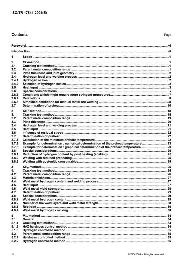
Contents Page
Foreword.vi
Introduction .vii
1 Scope .1
2 CE-method.1
2.1 Cracking test method .1
2.2 Parent metal composition range.1
2.3 Plate thickness and joint geometry .2
2.4 Hydrogen level and welding process .2
2.4.1 Hydrogen scales .2
2.4.2 Selection of hydrogen scales .2
2.5 Heat input .3
2.6 Special considerations.7
2.6.1 Conditions which might require more stringent procedures.7
2.6.2 Relaxations.8
2.6.3 Simplified conditions for manual metal-arc welding .8
2.7 Determination of preheat .10
3 CET-method.18
3.1 Cracking test method .18
3.2 Parent metal composition range.19
3.3 Plate thickness.20
3.4 Hydrogen level and welding process .21
3.5 Heat input .21
3.6 Influence of residual stress .22
3.7 Determination of preheat .22
3.7.1 Calculation of the minimum preheat temperature.22
3.7.2 Example for determination : numerical determination of the preheat temperature .23
3.7.3 Example for determination : graphical determination of the preheat temperature .23
3.8 Special considerations.25
3.8.1 Reduction of hydrogen content by post heating (soaking) .25
3.8.2 Welding with reduced preheating .25
3.8.3 Welding with austenitic consumables.25
4 CE -method .25
N
4.1 Cracking test method .25
4.2 Parent metal composition range.26
4.3 Material thickness.27
4.4 Weld metal hydrogen content and welding process.27
4.5 Heat input .27
4.6 Weld metal yield strength .28
4.7 Determination of preheat .29
4.8 Special considerations.29
4.8.1 Weld metal hydrogen content .29
4.8.2 Number of the weld layers and weld metal strength.30
4.8.3 Restraint .30
4.8.4 Weld metal hydrogen cracking.30
5 P -method .34
cm
5.1 General.34
5.1.1 Cracking test method .34
5.1.2 HAZ hardness control method .34
5.1.3 Hydrogen controlled method.35
5.2 Parent metal composition range.35
5.2.1 Hardness controlled method.35
5.2.2 Hydrogen controlled method.35
iv © ISO 2004 – All rights reserved
5.2.3 Selection of method .35
5.2.4 Hydrogen controlled method .36
5.3 Plate thickness and joint geometry .36
5.3.1 HAZ hardness controlled method.36
5.3.2 Hydrogen controlled method .36
5.4 Hydrogen levels and welding process .37
5.4.1 HAZ hardness controlled method.37
5.4.2 Hydrogen controlled method .37
5.5 Energy input.37
5.6 Special considerations.38
5.7 Determination of minimum preheat.38
5.7.1 Method according to value of CE.38
5.7.2 HAZ hardness controlled method.38
5.7.3 Hydrogen content controlled method .39
Annex A (informative) Comparison of the different methods.48
A.1 General.48
A.2 Parent metal composition range.48
A.3 Plate thickness and joint geometry .48
A.4 Hydrogen levels .49
A.5 Heat input .49
A.6 Prediction comparison.49
A.7 Summary and conclusions.50
Annex B (informative) Abbreviations . .71
Bibliography.72
Foreword
This document CEN ISO/TR 17844:2004 has been prepared by Technical Committee CEN/TC 121 “Welding”, the
secretariat of which is held by DIN, in collaboration with Technical Committee ISO/TC 44 “Welding and allied
processes”.
This document includes a Bibliography.
vi © ISO 2004 – All rights reserved
Introduction
The purpose of this document is to compare currently available methods for determining welding procedures for
avoiding hydrogen induced cold cracking during fabrication.
This subject has been extensively studied in recent years and many methods of providing guidance on avoidance
of cold cracking have been published. These methods vary considerably in how comprehensively the subject has
to be treated. It was considered appropriate to set certain important working criteria for selecting the published
methods to be included in this document. In deciding which criteria would be adopted it was agreed that these
should include the capabilities for effective use by industry, the end user. Thus the methods should be able to be
used on the basis of traditionally available information and relevant factors. The agreed list of criteria was set to
include the following main input parameters
steel composition;
welding heat input;
joint geometry and material thickness;
weld hydrogen level;
preheat
and in addition
graphical/computer format of data.
Using the above criteria, the following methods were selected.
CE (EN 1011-2/ISO/TR 17671-2, C.2-Method A);
CET (EN 1011-2/ISO/TR 17671-2, C.3-Method B);
CE (JIS B 8285);
N
P (ANSI/AWS D1.1).
cm
Each method is considered in a separate clause, under the following headings.
Description of type of test data used to devise the guidelines, e.g. CTS, y-groove, etc;
Parent metal composition and range of applicability;
Material thickness and range of applicability;
Hydrogen level and welding processes;
Heat input;
Other factors/special considerations;
Determination of preheat (step-by-step example description).
An informative Annex compares and contrasts the predictions of the methods in respect of ten different steels and
a range of material thickness, joint geometry's, heat inputs and hydrogen levels.
It is important that any calculations using a given method are undertaken using the current edition of the
appropriate standard.
1 Scope
In addition to EN 1011-2/ISO/TR 17671-2, this document contains further methods for avoidance of cold cracking
used by other members of ISO. This document gives guidance for manual, semi-mechanized, mechanized and
automatic arc welding of ferritic steels, excluding ferritic stainless steels, in all product forms.
Further information about the materials and process parameters is given in Clauses 2 to 5.
NOTE 1 All references are listed in the annex "Bibliography".
NOTE 2 All used abbreviations in this document are explained in EN 1011-2/ISO/TR 17671-2 and Annex B.
2 CE-method
2.1 Cracking test method
This method is based on an original concept of critical hardness to avoid HAZ (heat affected zone) hydrogen
cracking. It has been empirically developed incorporating the extensive results of HAZ hardenability studies and
cracking tests, the latter mainly but not exclusively being the CTS test type. In its present general format the
scheme was originally published in 1973 and, with modifications and updates, has been continuously incorporated
in British Standards for nearly 25 years. The experience of its use, both in the UK and elsewhere, has been
extremely satisfactory.
2.2 Parent metal composition range
The parent metals covered are carbon, carbon manganese, fine grained and low alloyed steels (groups 1 to 3 of
CR ISO 15608:2000).
The steels that were used over many years to develop the method have covered a wide range of compositions and
it is believed that they are adequately represented by Table 1.
Table 1 — Range of chemical composition of the main constituents for parent metal for CE-method
Element Percentage by weight
Carbon ≥ 0,05 ≤ 0,25
Silicon ≤ 0,8
Manganese ≤ 1,7
Chromium ≤ 0,9
Copper ≤ 1,0
Nickel ≤ 2,5
Molybdenum ≤ 0,75
Vanadium ≤ 0,20
Carbon equivalent values (in %) for parent metals are calculated using the following equation (1):
Mn Cr +Mo +V Ni +Cu
CE =C + + + (1)
IIW
6 5 15
and are applicable to steels with carbon equivalents in the range CE = 0,30 % to 0,70 %.
If of the elements in this formula only carbon and manganese are stated on the mill sheet for carbon and carbon
manganese steels, then 0,03 % should be added to the calculated value to allow for residual elements and
impurities. Where steels of different carbon equivalents or grades are to be joined, the higher carbon equivalent
value should be used.
This carbon equivalent formula may not be suitable for boron containing steels.
2.3 Plate thickness and joint geometry
The influence of plate thickness and joint geometry is determined by calculating the combined thickness. This
should be determined as the sum of the parent metal thickness averaged over a distance of 75 mm from the weld
centre line (see Figure 1).
Combined thickness is used to assess the heat sink of a joint for the purpose of determining the cooling rate.
If the thickness increases greatly beyond 75 mm from the weld centre line, it may be necessary to use a higher
combined thickness value.
Steels with thicknesses, t, in the range 6 mm ≤ t ≥ 100 mm were used in the tests to develop the scheme.
2.4 Hydrogen level and welding process
2.4.1 Hydrogen scales
The hydrogen scales to be used for any arc welding process depend principally on the weld diffusible hydrogen
content (according to EN ISO 3690) and should be as given in Table 2.
Table 2 — Hydrogen scales
Diffusible hydrogen content Hydrogen scale
(ml/100 g deposited material)
> 15 A
10 ≤ 15 B
5 ≤ 10 C
3 ≤ 5 D
≤ 3 E
Data from a wide range of arc welding processes has been used in developing the scheme and these include
manual metal arc (111), gas metal arc with solid wire (131, 135) and tubular wire (136, 137), the latter of both gas
shielded and self shielded types, and submerged arc welding (121).
NOTE The numbers in brackets are process numbers according to EN ISO 4063.
2.4.2 Selection of hydrogen scales
The following is general guidance on the selection of the appropriate hydrogen scale for various welding
processes.
2 © ISO 2004 – All rights reserved
Manual metal arc welding with basic covered electrodes can be used with the scale B to D depending on the
electrode manufacturer's/supplier's classification of the consumable. Manual metal arc welding with rutile or
cellulosic electrodes should be used with scale A.
Flux cored or metal cored consumables can be used with scales B to D depending on the manufacturer's/supplier's
classification of the wire electrodes. Submerged arc welding with one wire electrode (121) and flux consumable
combinations can have hydrogen levels appropriate to scales B to D, although most typically these will be scale C
but therefore need assessing for each named product combination and condition. Submerged arc fluxes can be
classified by the manufacture/supplier but this does not necessarily confirm that a practical flux wire combination
also meets the same classification.
Solid wire electrodes for gas-shielded arc welding (131, 135) and for TIG welding (141) may be used with scale D
unless specifically assessed and shown to meet scale E. Scale E may also be found to be appropriate for some
cored wires (136, 137) and some manual metal arc covered electrodes, but only after specific assessment. In
achieving these low levels of hydrogen consideration should be given to the contribution of hydrogen from the
shielding gas composition and atmospheric humidity.
For plasma arc welding (15), specific assessment should be made.
NOTE The numbers in brackets are process numbers according to EN ISO 4063.
2.5 Heat input
Heat input values (in kJ/mm) for use with Figure 2 a) to m) should be calculated in accordance with EN 1011-1/
ISO/TR 17671-1 and EN 1011-2/ISO/TR 17671-2.
For manual metal-arc welding, heat input values are expressed in Tables 3 to 6 in terms of electrode size and weld
run lengths.
The details given in Tables 3 to 6 relate to electrodes having an original length of 450 mm. For other electrode
lengths the following equation (2) may be used:
()Electrode diameter ××L F
Run length()mm =
Heat input
(2)
where
L is the consumed length of the electrode (in mm) (normally the original length of 450 mm less 40 mm for
stub end);
F is a factor (in kJ/mm ) having a value depending on the electrode efficiency, as follows:
efficiency approximately 95 % F = 0,0368
95 % < efficiency ≤ 110 % F = 0,0408
110 % < efficiency ≤ 130% F = 0,0472
efficiency > 130% F = 0,0608
Table 3 — Run length for manual metal-arc welding – 95 % electrode efficiency, approximately
Heat Run length from 410 mm of a 450 mm electrode of diameter
input
2,5 3,2 4,0 5,0 6,0 6,3
kJ/mm
mm mm mm mm mm mm
0,8 120 195 300 470
1,0 95 155 240 375 545 600
1,2 130 200 315 450 500
1,4 110 170 270 390 430
1,6 95 150 235 340 375
1,8 85 135 210 300 335
2,0 120 190 270 300
2,2 110 170 245 270
2,5 95 150 215 240
3,0 80 125 180 200
3,5 110 155 170
4,0 95 135 150
4,5 85 120 135
5,0 110 120
5,5 100 110
4 © ISO 2004 – All rights reserved
Table 4 — Run length for manual metal-arc welding – 95% < electrode efficiency ≤ 110%
Heat Run length from 410 mm of a 450 mm electrode of diameter
input 2,5 3,2 4,0 5,0 6,0 6,3
kJ/mm
mm mm mm mm mm mm
0,8 130 215 325 525
1,0 105 170 270 420 600
1,2 85 145 225 350 500 555
1,4 120 190 300 430 475
1,6 105 165 260 375 415
1,8 95 150 230 335 370
2,0 85 135 210 300 330
2,2 120 190 275 300
2,5 105 165 240 265
3,0 90 140 200 220
3,5 120 170 190
4,0 105 150 165
4,5 95 135 150
5,0 85 120 135
5,5 110 120
Table 5 — Run length for manual metal-arc welding – 110 %< electrode efficiency ≤ 130 %
Heat Run length from 410 mm of a 450 mm electrode of diameter
input 2,5 3,2 4,0 5,0 6,0 6,3
kJ/mm
mm mm mm mm mm mm
0,8 150 250 385 605
1,0 120 200 310 485
1,2 100 165 260 405 580
1,4 85 140 220 345 500 550
1,6 125 195 300 435 480
1,8 110 170 270 385 425
2,0 100 155 240 350 385
2,2 90 140 220 315 350
2,5 125 195 280 305
3,0 105 160 230 255
3,5 90 140 200 220
4,0 120 175 190
4,5 110 155 170
5,0 95 140 155
5,5 90 125 140
6 © ISO 2004 – All rights reserved
Table 6 — Run length for manual metal-arc welding – electrode efficiency > 130%
Heat Run length from 410 mm of a 450 mm electrode of diameter
input 3,2 4,0 5,0 6,0 6,3
kJ/mm
mm mm mm mm mm
0,8 320 500
1,0 255 400 625
1,2 215 330 520
1,4 180 285 445
1,6 160 250 390 560 620
1,8 140 220 345 500 550
2,0 130 200 310 450 495
2,2 115 180 285 410 450
2,5 100 160 250 360 395
3,0 85 135 210 300 330
3,5 115 180 255 285
4,0 100 155 225 245
4,5 90 140 200 220
5,0 125 180 200
5,5 115 165 180
2.6 Special considerations
2.6.1 Conditions which might require more stringent procedures
The preheating conditions presented in Figure 2 a) to m) have been found from experience to provide a satisfactory
basis for deriving safe welding procedures for many welded fabrications. However, the risk of hydrogen cracking is
influenced by several parameters and these can sometimes exert an adverse influence greater than accounted for
in Figure 2 a) to m). The following covers some of the factors that may increase the risk of cracking to above that
envisaged in drawing up the data in Figure 2. Precise quantification of the effects of these factors on the need for a
more stringent procedure and on the changes to the welding procedure required to avoid cracking cannot be made
at present. The following should therefore be considered as guidelines only.
Joint restraint is a complex function of section thickness, weld preparation, joint geometry and the stiffness of the
structure. Welds made in section thicknesses above approximately 50 mm and root runs in double bevel butt joints
may require more stringent procedures.
Certain welding processes may not be adequate for avoiding weld metal hydrogen cracking when welding steels of
low carbon equivalent. This is more likely to be the case when welding thick sections (e.g. greater than
approximately 50 mm) and with higher heat inputs.
The use of higher strength alloyed weld metal or carbon manganese weld metal with a manganese content above
approximately 1,5 % may lead to higher operative stresses. Whether or not this causes an increased risk of HAZ
cracking, the weld deposit would generally be harder and more susceptible to cracking itself, and in this condition
increased precautions against hydrogen cracking are advised.
Experience and research have indicated that lowering the inclusion content of the steel, principally by lowering the
sulphur content (but also the oxygen content), may increase the hardness of the heat-affected zone, and possibly
cause a small increase in the risk of HAZ hydrogen cracking. Accurate quantification of the effect is not presently
practicable.
Although modifications to the procedures to deal with welds involving the above factors can, in principle, be
obtained through a change in heat input or preheat or weld hydrogen level, the most effective modification is to
lower the weld hydrogen level. This can be done either directly, by lowering the weld hydrogen input to the weld
(use of lower hydrogen welding processes or consumables), or by increasing hydrogen loss from the weld by
diffusion through the use of post-heat for a period of time after welding. The required post-heat time will depend on
many factors, but a period of 2 h to 3 h has been found to be beneficial in many instances. It is recommended that
the required modifications to the procedures be derived by the use of adequate joint simulation weld testing.
2.6.2 Relaxations
Relaxations of the welding procedures may be possible under the following conditions:
General preheating. If the whole component or a width more than twice that stated in Clause 12 of EN 1011-2 :
2001 (ISO/TR 17671-2:2002) is preheated, it is generally possible to reduce the preheating temperature by a
limited amount;
Limited heat sink. If the heat sink is limited in one or more directions (e.g. when the shortest heat path is less
than ten times the fillet leg length) especially in the thicker plate (e.g. in the case of a lap joint where the
outstand is only marginally greater than the fillet weld leg length), it is possible to reduce preheating levels;
Austenitic consumables. In some circumstances where sufficient preheating to ensure crack-free welds is
impracticable an advantage may be gained by using certain austenitic or high nickel alloyed consumables. In
such cases preheat may not be necessary, especially if the condition of the consumable is such as to deposit
weld metal containing very low levels of hydrogen;
Joint fit up. Close fillet welds (where the gap is 0,5 mm or less) may justify relaxation in the welding procedure.
2.6.3 Simplified conditions for manual metal-arc welding
Where single run minimum leg length fillet welds are specified in the design, Table 7 may be used to obtain the
approximate heat input values for use in determining the welding procedure from Figure 2.
8 © ISO 2004 – All rights reserved
Table 7 — Values for heat input for manual metal-arc welding of single run fillet welds
a
Minimum leg Heat input for electrodes with covering types and electrodes
length efficiencies
mm
R and RR < 110 % B < 130 % R and RR > 130 %
kJ/mm kJ/mm kJ/mm
4 0,8 1,0 –
5 1,1 1,4 0,6
6 1,6 1,8 0,9
8 2,2 2,7 1,3
a
Covering types (R, RR, B) see EN 499/ISO 2560.
These values are appropriate for the practical situation where a contractor is required to make single run fillet welds
of a specified dimension related to the minimum leg length of the fillet welds, and where in practice one leg would
be longer than that minimum, as for example in a horizontal-vertical fillet weld (position PB according to
EN ISO 6947) and the data is therefore not appropriate for direct conversion to welds of specified throat dimension.
In other cases heat input should be controlled by control of electrode runout (see Table 6) or directly through
welding parameters.
2.7 Determination of preheat
Table 8 — Steps for the determination of preheat
Step Terms Clause/Figure/ Example
equation
1 Determine the carbon equivalent of the steel. This may be Equation (1) 0,45 %
assessed by reference to mill certificates or the maximum
carbon equivalent in the steel standard.
2 Determine the hydrogen scale of the welding process and 2.4 and Table 2 Manual metal-arc welding
consumable as hydrogen scale A, B, C, D or E and that the weld hydrogen
level is appropriate to scale
B in Table 2
3 Determine whether the joint is a fillet or butt weld. – Butt weld
4 From Figure 2 select the appropriate graph for scale B and – Figure 2 e)
carbon equivalent of 0,45. Use Figure 2 e). When a graph
for the selected hydrogen scale and carbon equivalent is
not available use the graph appropriate to the next highest
carbon equivalent value.
5 Determine the heat input to be used. This can be done Table 5 Assume this will be
either by reference to 2.5 or by using the minimum run deposited with a 4 mm
dimensions for the butt weld. electrode to be run out in
about 260 mm of run length
1,2 kJ/mm
6 Determine the combined thickness of the butt joint, – Assume calcuated combined
referring to 2.3. thickness of 50 mm
7 Using Figure 2 e), plot the co-ordinates of 1,2 kJ/mm heat – 75 ºC
input and 50 mm combined thickness. The preheating
temperature to be used should be obtained by reading the
preheat line immediately above or to the left of the co-
ordinated point for the heat input and combined thickness.
Read off minimum preheating and interpass temperature
required. Variation at step 7. In the event that the preheat is
undesirable, proceed as follows.
8 Re-examine Figure 2 e) to determine the minimum heat – For butt weld example:
input for no preheat (20 ºC line, normally). 1,4 kJ/mm
9 If by reference to Table 5 and consideration of welding – –
position this heat input is feasible, proceed using electrode
diameter and run length chosen from Table 5. If not
feasible, proceed to step 10.
10 Using Figure 2 a) and d) examine the feasibility for using – –
lower hydrogen levels (by the use of higher electrode
drying temperatures or change of consumables or change
of the welding process) to avoid the need for preheat at
acceptable heat input levels.
10 © ISO 2004 – All rights reserved
d = average thickness over a length of 75 mm
Combined thickness = d + d + d
1 2 3
Combined thickness = ½ (D + D ) to take account of heat sink.
1 2
Maximum diameter 40 mm for bar
Figure 1 — Examples for determination of combined thickness
Figure 2a)
Figure 2b)
12 © ISO 2004 – All rights reserved
Figure 2c)
Figure 2d)
Figure 2e)
Figure 2f)
14 © ISO 2004 – All rights reserved
Figure 2g)
Figure 2h)
Figure 2i)
Figure 2j)
16 © ISO 2004 – All rights reserved
Figure 2k)
Figure 2l)
Figure 2m)
Key
4 Scale
1 Combined thickness, mm
5 To be used for carbon equivalent not exceeding
2 Heat input, kJ/mm
3 Minimum preheating temperature, ºC
Figure 2 — Conditions for welding with defined carbon equivalents
3 CET-method
3.1 Cracking test method
This method of calculating the minimum preheat temperature for arc welding is based mainly on the results of the
y-joint (Tekken) weld cracking test and butt welds. Fillet welding data, mainly resulting from the CTS-test type, has
also been incorporated. It should be noted that single run fillet welds (CTS tests) show a lower restraint than the
critical root runs in butt welds (Tekken tests). The different preheat temperature amounted approximately to 60 °C.
Therefore the calculated preheat temperature for fillet welds might be too stringent. It is up to the experience of the
fabricator to use this advantage. To determine the preheat temperature of fillet and butt welds with different plate
thicknesses the thicker parent metal should always be used as the basis for the calculation. Multi run fillet welds
show a restraint similar to butt welds. Therefore it is preferable to use the same preheat temperature as for butt
welds.
The investigations were carried out in the early 1980s and published as IIW-Documents IX-1630-91 and IX-1631-
91. After successful application especially in welding high-strength low-alloyed steels with yield strengths up to
960 N/mm the method was introduced in Stahl Eisen Werkstoffblatt SEW 088, a German national guideline for
welding. The application of the method has been proven to predict conditions for welded joints that will not induce
cold cracking.
According to extensive investigations, the cold cracking behaviour is mainly influenced by the chemical composition
of the parent metal and the weld metal, the plate thickness, the hydrogen content of the weld metal, the heat input
and the residual stress. A brief overview of these influencing factors is given in 3.2 to 3.5.
18 © ISO 2004 – All rights reserved
3.2 Parent metal composition range
The parent metals included are fine grained low alloyed steels as well as unalloyed steels of groups 1 to 4 and 11
in accordance with CR ISO 15608:2000. The range of composition is also detailed in Table 9.
Table 9 — Range of chemical composition of the main constituents for parent metal for the CET-method
Element Percentage by weight
Carbon 0,05 to 0,32
Silicon ≤ 0,8
Manganese 0,5 to 1,9
Chromium ≤ 1,5
Copper ≤ 0,7
Molybdenum ≤ 0,75
Niobium ≤ 0,06
Nickel ≤ 2,5
Titanium ≤ 0,12
Vanadium ≤ 0,18
Boron ≤ 0,005
The effect of the chemical composition on the cold cracking susceptibility is characterised by the carbon equivalent,
CET, which is defined (in %) as:
Mn +Mo Cr +Cu Ni
CET =C + + + (3)
10 20 40
Within the range of the chemical composition detailed in Table 9 usual CET values are between 0,2 % and 0,5 %.
Normally, the higher value either of the parent metal or the weld metal increased by 0,03 % is to be used.
Table 10 — Range of validity
Abbreviation Term Dimension Range of validity
d Thickness mm 10 ≤ d ≤ 90
HD Hydrogen content ml/100 g 1 ≤ HD ≤ 20
Q Heat input kJ/mm 0,5 ≤ Q ≤ 4,0
YS Yield strength N/mm YS ≤ 1 000
A linear relationship exists between the carbon equivalent CET and the preheat temperature T .
p
T = 750 ×CET −150 (4)
pCET
Key
1 T in ºC
pCET
2 Carbon equivalent CET in %
Figure 3 — Preheat temperature in relation to CET
Figure 3 shows that an increase of about 0,01 % in the carbon equivalent, CET, leads to an increase of about
7,5 °C in the preheat temperature.
3.3 Plate thickness
The relationship between plate thickness, d, and preheat temperature, T , is given in equation (5) and Figure 4. In
p
the case of different parent metal thickness, the thickness of the thicker one is relevant.
T = 160 × tanh(d / 35) −110 (5)
pd
Key
1 T in ºC
pd
2 Plate thickness d in mm
Figure 4 — Preheat temperature in relation to the plate thickness
Figure 4 shows that a change in thickness exerts a strong influence in cases where the plate thickness is < 40 mm.
This influence diminishes, however, with increasing plate thickness and is only small for thickness > 60 mm.
20 © ISO 2004 – All rights reserved
3.4 Hydrogen level and welding process
The effect of hydrogen content, HD, of the weld metal according to EN ISO 3690 on preheat temperature level is
given in equation (6) and Figure 5.
0,35
T = 62 ×HD −100 (6)
pHD
Key
1 T in ºC
pHD
2 Hydrogen content HD in ml/100g
Figure 5 — Preheat temperature in relation to hydrogen content, HD
Figure 5 shows that an increase of hydrogen content (HD) requires an increase of the preheat temperature. A
change in hydrogen content has a greater effect on the preheat temperature for lower concentrations than for
higher ones.
A reduction in the hydrogen content of the weld metal by the use of correctly dried and baked consumables or
consumables with very low hydrogen levels for manual metal arc welding (111) and submerged arc welding (121)
leads to a remarkable reduction in the required preheat temperature.
However, the most favourable welding process in this context is gas shielded arc welding with solid wire (131, 135)
resulting in a hydrogen content of about 2,0 ml/100g deposit weld metal.
NOTE The numbers in brackets are process numbers according to EN ISO 4063.
3.5 Heat input
Values of the heat input, Q, (in kJ/mm) for use with Figure 6 should be calculated in accordance with EN 1011-1
and EN 1011-2.
The influence of the heat input, Q, on the preheat temperature is given in equation (7) and Figure 6.
T = (53×CET − 32) ×Q − 53×CET + 32 (7)
pQ
Key
1 T in ºC
pQ
2 Heat input Q in kJ/mm
Figure 6 — Preheat temperature in relation to heat input, Q
Figure 6 shows that an increase in the heat input during welding permits a reduction of the preheat temperature.
Furthermore the influence depends on the alloy content and is more pronounced for a low carbon equivalent than
for a higher one. If other than the given CET values are required they have to be interpolated from the plotted
curves. However the maximum heat input may be restricted by the effect on the toughness of the HAZ and weld
metal.
3.6 Influence of residual stress
The relationship between the residual stress level and the preheat temperature is known only to a qualitative
extent. An increase in the residual stresses and constraint results in an increase in the required preheat
temperature. In deriving the equation for calculating the preheat temperature, it has been assumed that residual
stresses in the weld region correspond to the yield strength of the parent metal or the weld metal.
3.7 Determination of preheat
3.7.1 Calculation of the minimum preheat temperature
The effect of the above mentioned influencing factors are summarized in a formula. In the case of different parent
metal thicknesses the thicker one is relevant. The
...