

ISO 19905-4:2026
(Main)Site-specific assessment of mobile offshore units — Part 4: Jack-up installation and removal at a site
- Abstract
This document specifies requirements and guidance for the installation on and removal from site of independent leg jack‑ups for use in the oil and gas industries including lower carbon energy. It addresses the assessment of: the installation operation from when the jack-up enters the defined safety zone of the host platform or the intended site to when it is elevated to the operating hull elevation above LAT and is ready for operations; the removal operation from when the jack-up is ready to jack-down to when it departs the defined safety zone. NOTE 1 Whilst this document is for independent leg jack-ups, many of the provisions can be applied to mat-supported jack-ups. When the jack-up has propulsion assist or is self-propelled, the provisions of this document related to positioning can be replaced or supplemented as appropriate. This document excludes the move of the jack-up between sites and elevated operations, which are covered respectively by IMO/Class and ISO 19905-1. NOTE 2 Whilst this document addresses the installation and removal of a jack-up at a site, RMPs normally include the move of the jack-up between sites (see example RMP in Annex E).
- Status
- Published
- Publication Date
- 25-Aug-2026
- Technical Committee
- ISO/TC 67/SC 7 - Offshore structures
- Drafting Committee
- ISO/TC 67/SC 7 - Offshore structures
- Current Stage
- 6060 - International Standard published
- Start Date
- 26-Aug-2026
- Due Date
- 05-Sep-2026
- Completion Date
- 26-Aug-2026
Buy Documents

ISO 19905-4:2026 - Site-specific assessment of mobile offshore units — Part 4: Jack-up installation and removal at a site

ISO 19905-4:2026 - Évaluation spécifique au site d'unités mobiles en mer — Partie 4: Déploiement et repliement de plates-formes auto élévatrices sur site
ISO 19905-4:2026 is an International Standard published by ISO for site-specific assessment of mobile offshore units. It specifies requirements and guidance for the installation on and removal from site of independent leg jack-ups used in the oil and gas industries, including lower carbon energy, and it is aimed at assessors, jack-up owners, operators, and the marine assurance and rig-move teams that plan and control those operations.
What does ISO 19905-4:2026 specify?
ISO 19905-4:2026 specifies how to assess jack-up installation and removal at a specific site, from entry into the defined safety zone to the point where the unit is ready for operations or has departed the zone. It is organized around scope, normative references, terms and definitions, symbols and abbreviated terms, overall considerations, operability limits, data and preparation, rig move procedure development, supplementary engineering analyses, and supplementary seabed activities.
| Annex | What it covers |
|---|---|
| Annex A | Additional information and guidance aligned to the main clauses |
| Annex B | Data to gather and exchange, plus checklists for installation and removal |
| Annex C | Competence of the rig mover |
| Annex D | Example steps for entering and departing safety zones and responsible parties |
| Annex E | Example Rig Move Procedure (RMP) |
ISO 19905-4:2026 is written for independent leg jack-ups. Many of its provisions can also be applied to mat-supported jack-ups, and positioning provisions can be replaced or supplemented when the jack-up has propulsion assist or is self-propelled. The document excludes movement between sites and elevated operations, which are covered respectively by IMO/Class and ISO 19905-1.
What are the key requirements of ISO 19905-4:2026?
ISO 19905-4:2026 requires a site-specific installation and removal assessment (SSA-I) to be used together with the site-specific assessment elevated (SSA-E) from ISO 19905-1. In practice, that means the team should treat installation/removal planning and elevated survival assessment as linked parts of the same site decision.
Assessment structure and planning
Clause 5 says the SSA-I and SSA-E are separate parts of the overall site-specific assessment, and site-specific rig move procedure(s) shall be developed for both installation and removal. The standard also requires competent assessors, adequate planning, and timely arrangements for travel logistics, certifications, and site access. This matters because the same people, data, and constraints often affect both assessments, and missing them early can make the operation inefficient or non-viable.
Jack-up suitability and regulatory basis
Clause 5 also requires the jack-up to be structurally sound and adequately maintained. That is met by valid classification society certification from a recognized classification society (RCS) throughout the operation, or by verification by an independent competent body to RCS standards with periodic inspection. The operator and jack-up owner are responsible for identifying applicable national regulations for the specific site and operation.
Hazard identification and operability limits
Clause 6 requires identification of potential causes, effects, and consequences of damage during planning. Clause 7 requires operability limits to be clearly defined for installation and removal, including loading, motion, and metocean limits. These limits may come from the marine operating manual (MOM) or from a site-specific analysis using Clause 10. In practice, this gives the team the threshold values that decide whether to proceed, pause, or change method.
Data, studies, and risk management
Clause 8 requires collection of site data and jack-up data, review of elevated suitability, preparation of installation and removal guidance, risk assessment, operational advisory, marine assurance, and management of change (MOC). The operator shall conduct the SSA-I risk assessment with participation by the jack-up owner, and it shall be reviewed and updated just before the operation. The hazards explicitly include contact with surface or sub-surface assets, foundation issues, mooring and positioning, unexploded ordnance (UXO), structural and mechanical failure, loss of watertight integrity or capsize, hydrocarbon release, dropped objects on subsea assets, and data inaccuracy. This is the core practical safety step: it turns site knowledge into documented controls.
Rig move procedure and operational control
Clause 9 requires a rig move procedure (RMP) for each move, agreed by the operator and, if engaged, the marine warranty survey company (MWS). The RMP shall include reference documents, move-specific factors, chain of command, roles and responsibilities, MOC, minimum essential personnel, mitigation measures from the risk assessment, at least two independent site-specific weather forecasts, confirmation stage, execution stage, acceptance criteria for the installed condition, information retention, and sign-off. The confirmation stage must verify that metocean conditions and forecasts are within limits, positioning and towing equipment are suitable, the jack-up and platform are prepared, and subsea infrastructure is located and marked.
Installed condition and record keeping
Clause 9 also requires review of the installed condition against the assumptions used in the SSA-E and the RMP. The checks include leg penetration against the predicted load-penetration curve, final preload applied, preload reaction, preload jacking reaction, hull elevation above LAT, position and heading within the drilling window, loading condition, and holding system engagement. Rig move logs shall be kept for both installation and removal, and lessons learned shall be retained and shared as appropriate. This is important because the as-installed state can differ from the plan, and the recorded outcome affects later removal and future operations.
Supplementary engineering analyses and seabed activities
Clause 10 allows supplementary engineering analyses to refine operability limits for installation and removal, including stand-off location, positioning at site, preloading, punch-through mitigation, jacking into the water, leg extraction, and moving away from site. Clause 11 covers supplementary seabed activities such as stomping, reaming, gravel pads, seabed excavation, perforation drilling, modification of the seabed to assist leg extraction, and scour protection. These are the technical tools used when the seabed or site geometry needs to be changed or better understood to make the move safe.
What terms does ISO 19905-4:2026 define?
ISO 19905-4:2026 defines the terms used to manage the assessment and operation of jack-ups at a site.
- site-specific assessment - the evaluation of jack-up stability and structural integrity, and where relevant seabed restraint or support, against the actions defined for the site.
- site-specific assessment - elevated (SSA-E) - the elevated survival assessment carried out in accordance with ISO 19905-1.
- site-specific assessment - installation and removal (SSA-I) - the assessment for jack-up installation on site and removal from site covered by this document.
- rig move procedure (RMP) - the procedural document covering movement of the jack-up from the removal site to the installation site.
- marine operating manual (MOM) - the latest approved document defining the jack-up’s operational characteristics and capabilities.
- marine warranty survey company (MWS) - the organization approved by insurance underwriters to review the warranted operation.
- defined safety zone - the safety zone around the host platform or operating location under the control of the offshore installation manager (OIM).
Who uses ISO 19905-4:2026?
ISO 19905-4:2026 is used by jack-up owners, operators, rig movers, marine warranty survey companies, assessors, and marine assurance teams. It is also relevant to drilling, offshore structures, and marine operations personnel who need to plan, review, approve, or execute jack-up installation and removal.
In practice, these roles use it to:
- plan site-specific installation and removal activities
- decide whether site conditions are within operability limits
- build and review the RMP
- define roles, communications, and hold points
- assess foundation, seabed, and weather-related risks
- document the as-installed condition and lessons learned
- support marine assurance and MOC decisions
Which standards are used with ISO 19905-4:2026?
ISO 19905-4:2026 names these normative references:
- ISO 19901-8 - provides marine soil investigations, which support seabed and foundation data for the assessment.
- ISO 19901-10 - provides marine geophysical investigations, which support site characterization and seabed understanding.
- ISO 19905-1:2023 - provides the elevated jack-up assessment, which is the companion part for survival at the site.
The document also points readers to related offshore standards in the ISO 19905 series and to ISO 19900 for analytical tools and general offshore structural concepts.
What does the ISO 19905-4:2026 document contain?
ISO 19905-4:2026 contains the clauses and annexes needed to plan, assess, and document jack-up installation and removal at a site. It includes a terms and definitions section, a symbols and abbreviated terms section, and detailed clauses on planning, hazards, operability limits, data collection, risk assessment, operational advisory, marine assurance, MOC, and RMP development.
The annexes add practical support. Annex B supplies data lists and checklists for installation and removal, including readiness and towing vessel surveys. Annex C describes rig mover competence in terms of experience, qualifications, training, and records. Annex D gives an example sequence of steps for entering and departing safety zones and identifies the responsible parties. Annex E gives an example RMP for reference, while the introduction and Annex A explain how the SSA-I fits with the SSA-E and with the broader rig move process.
Buy Documents
ISO 19905-4:2026 - Site-specific assessment of mobile offshore units — Part 4: Jack-up installation and removal at a site
ISO 19905-4:2026 - Évaluation spécifique au site d'unités mobiles en mer — Partie 4: Déploiement et repliement de plates-formes auto élévatrices sur site
Get Certified
Connect with accredited certification bodies for this standard

Element Materials Technology
Materials testing and product certification.

ABS Group Brazil
ABS Group certification services in Brazil.

ABS Quality Evaluations Inc.
American Bureau of Shipping quality certification.
Sponsored listings
Frequently Asked Questions
ISO 19905-4:2026 is a standard published by the International Organization for Standardization (ISO). Its full title is "Site-specific assessment of mobile offshore units — Part 4: Jack-up installation and removal at a site". This standard covers: This document specifies requirements and guidance for the installation on and removal from site of independent leg jack‑ups for use in the oil and gas industries including lower carbon energy. It addresses the assessment of: the installation operation from when the jack-up enters the defined safety zone of the host platform or the intended site to when it is elevated to the operating hull elevation above LAT and is ready for operations; the removal operation from when the jack-up is ready to jack-down to when it departs the defined safety zone. NOTE 1 Whilst this document is for independent leg jack-ups, many of the provisions can be applied to mat-supported jack-ups. When the jack-up has propulsion assist or is self-propelled, the provisions of this document related to positioning can be replaced or supplemented as appropriate. This document excludes the move of the jack-up between sites and elevated operations, which are covered respectively by IMO/Class and ISO 19905-1. NOTE 2 Whilst this document addresses the installation and removal of a jack-up at a site, RMPs normally include the move of the jack-up between sites (see example RMP in Annex E).
This document specifies requirements and guidance for the installation on and removal from site of independent leg jack‑ups for use in the oil and gas industries including lower carbon energy. It addresses the assessment of: the installation operation from when the jack-up enters the defined safety zone of the host platform or the intended site to when it is elevated to the operating hull elevation above LAT and is ready for operations; the removal operation from when the jack-up is ready to jack-down to when it departs the defined safety zone. NOTE 1 Whilst this document is for independent leg jack-ups, many of the provisions can be applied to mat-supported jack-ups. When the jack-up has propulsion assist or is self-propelled, the provisions of this document related to positioning can be replaced or supplemented as appropriate. This document excludes the move of the jack-up between sites and elevated operations, which are covered respectively by IMO/Class and ISO 19905-1. NOTE 2 Whilst this document addresses the installation and removal of a jack-up at a site, RMPs normally include the move of the jack-up between sites (see example RMP in Annex E).
ISO 19905-4:2026 is classified under the following ICS (International Classification for Standards) categories: 75.180.10 - Exploratory, drilling and extraction equipment. The ICS classification helps identify the subject area and facilitates finding related standards.
ISO 19905-4:2026 is available in PDF format for immediate download after purchase. The document can be added to your cart and obtained through the secure checkout process. Digital delivery ensures instant access to the complete standard document.
Standards Content (Sample)
International
Standard
ISO 19905-4
First edition
Site-specific assessment of mobile
2026-08
offshore units —
Part 4:
Jack-up installation and removal at
a site
Évaluation spécifique au site d'unités mobiles en mer —
Partie 4: Déploiement et repliement de plates-formes auto
élévatrices sur site
Reference number
© ISO 2026
All rights reserved. Unless otherwise specified, or required in the context of its implementation, no part of this publication may
be reproduced or utilized otherwise in any form or by any means, electronic or mechanical, including photocopying, or posting on
the internet or an intranet, without prior written permission. Permission can be requested from either ISO at the address below
or ISO’s member body in the country of the requester.
ISO copyright office
CP 401 • Ch. de Blandonnet 8
CH-1214 Vernier, Geneva
Phone: +41 22 749 01 11
Email: copyright@iso.org
Website: www.iso.org
Published in Switzerland
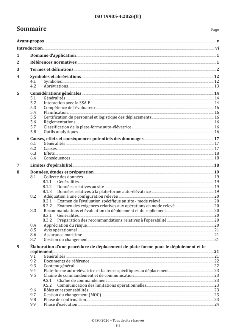
ii
Contents Page
Foreword .v
Introduction .vi
1 Scope . 1
2 Normative references . 1
3 Terms and definitions . 1
4 Symbols and abbreviated terms.11
4.1 Symbols .11
4.2 Abbreviated terms . 12
5 Overall considerations .13
5.1 General . 13
5.2 Interaction with SSA-E . 13
5.3 Competency of the assessor .14
5.4 Planning .14
5.5 Personnel certification and travel logistics .14
5.6 Regulations . 15
5.7 Classification of the jack-up . 15
5.8 Analytical tools . 15
6 Potential causes, effects and consequences of damage .15
6.1 General . 15
6.2 Causes .16
6.3 Effects .16
6.4 Consequences .16
7 Operability limits .16
8 Data, studies and preparation . 17
8.1 Collection of data .17
8.1.1 General .17
8.1.2 Site Data .17
8.1.3 Jack-up data .18
8.2 Elevated suitability . .18
8.2.1 Review of the Site-Specific Assessment – Elevated .18
8.2.2 Review of the requirements for the elevated operations .18
8.3 Installation and removal guidance and assessment .18
8.3.1 General .18
8.3.2 Preparation of operability guidance .18
8.4 Risk assessment .18
8.5 Operational advisory .19
8.6 Marine assurance .19
8.7 Management of change .19
9 Rig move procedure development for installation and removal . 19
9.1 General .19
9.2 Reference documents . 20
9.3 Outline contents . 20
9.4 Jack-up and move-specific factors . 20
9.5 Chain of command and communications .21
9.5.1 Chain-of-command .21
9.5.2 Communication of operational limitations .21
9.6 Roles and responsibilities .21
9.7 Management of change (MOC) .21
9.8 Confirmation stage .21
9.9 Execution Stage . 22
9.10 Acceptability of the installed condition . 22
iii
9.11 Installation information retention . 22
9.12 Removal information retention . 22
9.13 Sign-off of the RMP . 22
10 Supplementary engineering analyses . .22
11 Supplementary seabed activities .23
Annex A (informative) Additional information and guidance .24
Annex B (informative) Data and checklists .75
Annex C (informative) Rig mover competence .85
Annex D (informative) Example of the steps involved when entering and departing safety zones
and responsible parties .89
Annex E (informative) Example Rig Move Procedure (RMP) .91
Bibliography .92
iv
Foreword
ISO (the International Organization for Standardization) is a worldwide federation of national standards
bodies (ISO member bodies). The work of preparing International Standards is normally carried out through
ISO technical committees. Each member body interested in a subject for which a technical committee
has been established has the right to be represented on that committee. International organizations,
governmental and non-governmental, in liaison with ISO, also take part in the work. ISO collaborates closely
with the International Electrotechnical Commission (IEC) on all matters of electrotechnical standardization.
The procedures used to develop this document and those intended for its further maintenance are described
in the ISO/IEC Directives, Part 1. In particular, the different approval criteria needed for the different types
of ISO documents should be noted. This document was drafted in accordance with the editorial rules of the
ISO/IEC Directives, Part 2 (see www.iso.org/directives).
ISO draws attention to the possibility that the implementation of this document may involve the use of (a)
patent(s). ISO takes no position concerning the evidence, validity or applicability of any claimed patent
rights in respect thereof. As of the date of publication of this document, ISO had not received notice of (a)
patent(s) which may be required to implement this document. However, implementers are cautioned that
this may not represent the latest information, which may be obtained from the patent database available at
www.iso.org/patents. ISO shall not be held responsible for identifying any or all such patent rights.
Any trade name used in this document is information given for the convenience of users and does not
constitute an endorsement.
For an explanation of the voluntary nature of standards, the meaning of ISO specific terms and expressions
related to conformity assessment, as well as information about ISO's adherence to the World Trade
Organization (WTO) principles in the Technical Barriers to Trade (TBT), see www.iso.org/iso/foreword.html.
This document was prepared by Technical Committee ISO/TC 67, Oil and gas industries including lower carbon
energy, Subcommittee SC 7, Offshore structures.
A list of all parts in the ISO 19905 series can be found on the ISO website.
Any feedback or questions on this document should be directed to the user’s national standards body. A
complete listing of these bodies can be found at www.iso.org/members.html.
v
Introduction
The International Standards on offshore structures prepared by TC 67/SC 7 [i.e. ISO 19900,
ISO 19901 (all parts), ISO 19902, ISO 19903, ISO 19904-1, ISO 19905 (all parts) and ISO 19906] constitute
a common basis covering those aspects that address design requirements and assessments of all offshore
structures used in the energy sector worldwide. Through their application, the intention is to achieve
reliability levels appropriate for offshore structures, whatever the type of structure and the nature of the
materials used.
Structural integrity is an overall concept comprising models for describing actions, structural analyses,
design or assessment rules, safety elements, quality of work, quality control procedures and national
requirements, all of which are mutually dependent. The modification of one aspect of design or assessment
in isolation can disturb the balance of reliability inherent in the overall concept or structural system. The
implications involved in modifications, therefore, must be considered in relation to the overall reliability of
all offshore structural systems.
The International Standards on offshore structures prepared by TC 67/SC 7 are intended to provide wide
latitude in the choice of structural configurations, materials and techniques without hindering innovation.
Sound engineering judgment is, therefore, necessary in the use of these documents.
This document states the general principles and basic requirements for the site-specific assessment of the
installation and removal of mobile jack-ups; it is intended to be used for the site-specific assessment of
installation and removal and not for jack-up design.
The assessment of a jack-up at a specific site is normally comprised of two parts.
1) Assessing that the jack-up can survive in the operational elevated mode.
2) Assessing that the jack-up can be safely installed at, and removed from, the site.
Item 1 is addressed in ISO 19905-1 and item 2 is addressed in ISO 19905-4. When applicable, this document
can be supplemented with ISO 19905-1 for situations when the hull is partially elevated between water
surface and the full operational hull elevation.
Much of the information required for an ISO 19905-1 assessment (referred to herein as a site-specific
assessment elevated – SSA-E) is also required for an ISO 19905-4 assessment (referred to herein as a site-
specific installation and removal assessment – SSA-I). There is, however, additional information used in an
SSA-I that is best gathered at the same time that data for the SSA-E is collected. This is further discussed in
5.1.
Site-specific installation and removal assessment is normally carried out before a jack-up is installed
or removed at a specific site. The installation and removal assessment is not intended to provide a full
evaluation of the jack-up; it assumes that aspects not addressed herein e.g. the derivation of leg strength,
structural condition of the jack-up, have been addressed using other practices and standards or with the
assessment of survival conditions when elevated on the specific site. In some instances, the original design
of all or part of the structure can be in accordance with other International Standards on offshore structures
prepared by TC 67/SC 7, and in some cases, different practices or standards can have been applied.
The purpose of the site-specific installation and removal assessment is to ensure that the jack-up and
its foundations have been adequately assessed, taking into account the consequences of failure. It is
important that the results of a site-specific installation and removal assessment be appropriately recorded
and communicated to those persons required to know or act on the conclusions and recommendations.
Alternative approaches to the site-specific installation and removal assessment can be used, provided that
they have been shown to give a level of structural reliability equivalent, or superior, to that implicit in this
document.
The annexes can include terms, definitions and concepts that differ from those included in the mandatory
parts of this part of ISO 19905.
Annex A provides background to and guidance on the use of this document. The clause numbering in Annex A
is the same as in the main text in order to facilitate cross-referencing.
vi
Annex B identifies the documentation that should be gathered and exchanged and provides checklists of
information and actions for the stages of installation and removal operations.
Annex C provides guidance on the competence of the rig mover.
Annex D provides guidance on the parties responsible for entering and departing safety zones.
Annex E provides an example rig move procedure (RMP).
This document is structured to consider the issues associated with a particular site and is not necessarily
organized in the same way that a jack-up owner or surveyor would develop a rig move procedure (which is
normally developed in terms of leaving one site and being elevated at the next), see Figure 0-1.
Figure 0-1 — Alignment of specific assessments with multiple sites and rig moves
The provisions of this document form an integrated approach for SSA-I, which is intended to be used in its
entirety for the site-specific installation and removal assessment of an independent leg jack-up.
This document has been developed assuming that a site-specific assessment for elevated (survival)
operations (SSA-E) is available for the specific site. It can be possible to develop an incomplete RMP prior to
the SSA-E being finalized.
vii
International Standard ISO 19905-4:2026(en)
Site-specific assessment of mobile offshore units —
Part 4:
Jack-up installation and removal at a site
1 Scope
This document specifies requirements and guidance for the installation on and removal from site of
independent leg jack-ups for use in the oil and gas industries including lower carbon energy. It addresses the
assessment of:
a) the installation operation from when the jack-up enters the defined safety zone of the host platform
or the intended site to when it is elevated to the operating hull elevation above LAT and is ready for
operations;
b) the removal operation from when the jack-up is ready to jack-down to when it departs the defined safety
zone.
NOTE 1 Whilst this document is for independent leg jack-ups, many of the provisions can be applied to mat-
supported jack-ups.
When the jack-up has propulsion assist or is self-propelled, the provisions of this document related to
positioning can be replaced or supplemented as appropriate.
This document excludes the move of the jack-up between sites and elevated operations, which are covered
respectively by IMO/Class and ISO 19905-1.
NOTE 2 Whilst this document addresses the installation and removal of a jack-up at a site, RMPs normally include
the move of the jack-up between sites (see example RMP in Annex E).
2 Normative references
The following documents are referred to in the text in such a way that some or all of their content constitutes
requirements of this document. For dated references, only the edition cited applies. For undated references,
the latest edition of the referenced document (including any amendments) applies.
ISO 19901-8, Oil and gas industries including lower carbon energy — Offshore structures — Part 8: Marine soil
investigations
ISO 19901-10, Petroleum and natural gas industries — Specific requirements for offshore structures — Part 10:
Marine geophysical investigations
ISO 19905-1:2023, Oil and gas industries including lower carbon energy — Site-specific assessment of mobile
offshore units — Part 1: Jack-ups: elevated at a site
3 Terms and definitions
For the purposes of this document, the following terms and definitions apply.
ISO and IEC maintain terminology databases for use in standardization at the following addresses:
— ISO Online browsing platform: available at https:// www .iso .org/ obp
— IEC Electropedia: available at https:// www .electropedia .org/
3.1
action
external load applied to the jack-up (3.25) (direct action) or an imposed deformation or acceleration (indirect
action)
EXAMPLE An imposed deformation can be caused by fabrication tolerances, differential settlement, temperature
change or moisture variation. An imposed acceleration can be caused by an earthquake.
[SOURCE: ISO 19900:2019, 3.3, modified — "structure" changed to "jack-up".]
3.2
air gap
clearance between the highest water surface that occurs during the current phase of the installation or
removal operation and the base of the hull
Note 1 to entry: In ISO 19900, "air gap" is defined as the distance between the highest water elevation and the lowest
exposed part of the primary deck structure not designed to withstand associated environmental action effects for a
defined return period. This differs from the air gap definition historically used by the jack-up industry. In ISO 19905-1,
hull elevation above LAT (3.29) is used for the elevated operational case.
3.3
assessment
site-specific assessment
evaluation of the stability and structural integrity of a jack-up (3.25) and, where applicable, its seabed
restraint or support against the actions (3.1) determined in accordance with specific requirements
Note 1 to entry: The specific requirements are given in this document.
Note 2 to entry: An assessment can be limited to an evaluation of the components or members of the structure which,
when removed or damaged, could cause failure of the whole structure, or a significant part of it.
[SOURCE: ISO 19905-1:2023, 3.6]
3.4
assessment criteria
quantitative formulations describing the conditions to be fulfilled for each assessment situation (3.6)
[SOURCE: ISO 19900:2019, 3.15, modified — References to "design" deleted.]
3.5
assessment resistance
resistance limit calculated using factored representative values (3.46) of basic variables (3.10) or from
factored expressions based on unfactored representative values (3.46) of basic variables (3.10)
EXAMPLE Examples of basic variables relevant to resistance are material properties.
[SOURCE: ISO 19900:2019, 3.12, modified — "design" changed to "assessment".]
3.6
assessment situation
set of physical conditions for which the jack-up (3.25) or its components are verified
Note 1 to entry: The assessment situations are checked against the acceptance criteria (3.4) of this document to
demonstrate that the relevant limit states (3.28) are not exceeded.
[SOURCE: ISO 19900:2019, 3.16, modified — Reference to "design" deleted and "structure" changed to " jack-
up". Note 1 to entry added]
3.7
assessor
entity performing the site-specific assessment (3.3)
[SOURCE: ISO 19905-1:2023, 3.10]
3.8
backfill
submerged weight of all of the soil that can be present on top of the spudcan (3.59)
Note 1 to entry: Backfilling can occur during or after preloading (3.38). W refers to the submerged weight of
BF,o
the backfilling that occurs up to achieving the preload reaction (3.40). W refers to the submerged weight of the
BF,A
backfilling that occurs after the maximum preload has been applied and held. Both W and W can comprise
BF,o BF,A
either backflow (3.9) or infill (3.24), or both.
[SOURCE: ISO 19905-1:2023, 3.11, modified — In note 1 to entry, the last sentence has been removed.]
3.9
backflow
soil that flows from beneath the spudcan (3.59) around the sides and onto the top
Note 1 to entry: Backflow is part of backfill (3.8).
[SOURCE: ISO 19905-1:2023, 3.12]
3.10
basic variable
variable representing physical quantities which characterize actions (3.1) and environmental influences,
geometric quantities, or material properties including soil properties
Note 1 to entry: Basic variables are typically uncertain random variables or random processes used in the calculation
or assessment of representative values (3.46) of actions or resistance.
[SOURCE: ISO 19900:2019, 3.7]
3.11
certificate of approval
CoA
certificate issued by the marine warranty survey company (3.32) upon review of the rig move procedure
(3.48); documentation for the intended operations; weather conditions and weather forecast and checking
equipment
Note 1 to entry: Separate CoAs can be issued for the removal operation, the rig move, the installation on site and the
elevated operation (in relation to the ability to withstand elevated storm conditions).
3.12
chart datum
CD
local datum used to fix water depths on a chart or tidal heights over an area
Note 1 to entry: Chart datum is usually an approximation to the level of the lowest astronomical tide (3.29).
Note 2 to entry: Chart datum can differ from one chart to another and care is required if cross referencing sites that
are not on the same chart.
[SOURCE: ISO 19901-1:2026, 3.2, modified — Note 2 to entry has been added.]
3.13
characteristic value
value assigned to a basic variable (3.10) with a prescribed probability
Note 1 to entry: In some design/assessment situations, a variable can have two characteristic values, an upper value
and a lower value.
[SOURCE: ISO 19900:2019, 3.9]
3.14
contingency plan
plan to implement alternate operations in case safety or productivity is jeopardized
3.15
defined safety zone
safety zone around the host platform or operating location under the control of the platform or location OIM
(offshore installation manager)
Note 1 to entry: The zone typically extends 500 m from the host platform or operating location, and the zone can be
known as the 500 m zone.
3.16
field
general area where the jack-up (3.25) is intended to operate
Note 1 to entry: The field is a general area as opposed to the site (3.54) which is specific.
[SOURCE: ISO 19905-1:2023, 3.23]
3.17
fixed load
lightship
permanent parts of the jack-up (3.25), including hull, legs and spudcans (3.59), outfit, stationary and
moveable-fixed equipment
Note 1 to entry: Moveable-fixed equipment normally includes the drilling package structure and associated
permanently attached equipment.
[SOURCE: ISO 19905-1:2023, 3.24, modified — The admitted term "lightship" has been added.]
3.18
footprint
sea floor depression which remains when a jack-up (3.25) is removed from a site
[SOURCE: ISO 19905-1:2023, 3.25]
3.19
foundation
soil and spudcan (3.59) supporting a jack-up (3.25) leg
[SOURCE: ISO 19905-1:2023, 3.26]
3.20
hold point
point in time at which operations are paused for decision making
3.21
hull level jetting
jetting while applying excess buoyancy, thereby creating over pull with all legs stuck, alternating jetting
between legs as needed, or jetting all legs together, while keeping the hull as level as practical within
designer limitations, and freeing the legs as close together as reasonably practical
3.22
human error
human action or inaction that can produce an unintended result
3.23
independent leg jack-up
jack-up (3.25) unit with legs that can be raised and lowered independently
[SOURCE: ISO 19905-1:2023, 3.32]
3.24
infill
soil above the plan area of the spudcan (3.59) arising from sediment transport or hole sidewall collapse
Note 1 to entry: Infill is part of backfill (3.8).
[SOURCE: ISO 19905-1:2023, 3.34]
3.25
jack-up
mobile offshore unit with a buoyant hull and one or more legs that can be moved up and down relative to the
hull
Note 1 to entry: A jack-up reaches its operational mode by lowering the leg(s) to the seabed and then raising the hull
to the required elevation. The majority of jack-ups have three or more legs, each of which can be moved independently
and which are supported in the seabed by spudcans (3.59).
[SOURCE: ISO 19905-1:2023, 3.36]
3.26
jack-up owner
owner
representative of the company or companies owning or chartering the jack-up (3.25)
Note 1 to entry: The energy company, the operator (3.37), contracts the jack-up and is generally not the owner or
charterer.
[SOURCE: ISO 19905-1:2023, 3.37]
3.27
leg run
prolonged vertical leg movement that can be controlled by the jacking system, such that the hull can be
maintained within tolerable limits
3.28
limit state
state beyond which the jack-up (3.25) no longer satisfies the assessment criteria (3.4)
[SOURCE: ISO 19905-1:2023, 3.40, modified — The words "or a structural member" have been deleted]
3.29
lowest astronomical tide
LAT
level of low tide when all harmonic components causing the tides are in phase
Note 1 to entry: The harmonic components are in phase approximately once every 19 years, but these conditions are
approached several times each year.
[SOURCE: ISO 19901-1:2026, 3.18]
3.30
marine assurance
secondary review of marine installation and removal procedures
3.31
marine operating manual
marine operation manual
operating manual
latest approved document that defines the operational characteristics and capabilities of the jack-up (3.25)
Note 1 to entry: The assessor (3.7) should ensure that any updated weight data are provided.
3.32
marine warranty survey company
MWS
organization approved by insurance underwriters to satisfy the requirements of the warranty clause in a
marine insurance policy
Note 1 to entry: The fundamental objective of the MWS is to make reasonable endeavours to ensure that the risks
associated with the warranted operation (in this case, the rig move) are reduced to an acceptable level according
to the best industry practice. The MWS can specify recommendations to be met in order to minimize the risk to the
insured jack-up during all phases of the move and to comply with the terms of the warranty.
Note 2 to entry: MWS attendance is not always a requirement of the insurance warranty clause.
3.33
mat-supported jack-up
jack-up (3.25) unit with the leg(s) rigidly connected by a foundation structure, such that the leg(s) are raised
and lowered in unison
[SOURCE: ISO 19905-1:2023, 3.44]
3.34
neutral zone
hull draught zone through which there is vertical load reversal between the legs and the hull
Note 1 to entry: Hull and legs are independent of each other with neither tension nor compression being applied to the
jacking system.
Note 2 to entry: The extent of the zone can be larger in the presence of waves.
Note 3 to entry: At this draught, any backlash in the pinion to rack-teeth interface can have detrimental effects
(unwinding and rewinding of the planetary gear boxes) even with the brakes set in moderate swell conditions.
Note 4 to entry: The neutral buoyancy effects are most prevalent on floating jacking systems (i.e. causing bouncing of
jacking units between shock pads).
3.35
nominal value
value assigned to a variable specified or determined on a non-statistical basis, typically from acquired
experience or physical conditions, or as published in a recognized code or standard
Note 1 to entry: In some design/assessment situations, a variable can have two nominal values, an upper value and a
lower value
[SOURCE: ISO 19900:2019, 3.33]
3.36
operability limits
pre-defined conditions (e.g. metocean, motions, loads) outside which installation or removal operations are
to be suspended
3.37
operator
representative of the company or companies leasing the site
Note 1 to entry: The operator is normally the oil company acting on behalf of co-licensees.
[SOURCE: ISO 19900:2019, 3.35, modified — Note 2 to entry deleted.]
3.38
preloading
installation and embedment of the spudcans (3.59) by vertical loading of the soil beneath a jack-up leg
spudcan (3.59) with the objective of ensuring sufficient foundation capacity under assessment situations
(3.6) through to the time when the maximum load is applied and held
Note 1 to entry: Whilst three-legged jack-ups preload by taking water ballast on board, jack-ups with four or more
legs typically achieve foundation preload by carrying the hull weight on pairs of legs in turn. This procedure is known
as pre-driving and generally does not require the addition of water ballast. For the purposes of this document, no
distinction is made between preload and pre-drive.
[SOURCE: ISO 19905-1:2023, 3.55]
3.39
preloading air gap
distance between the baseline of the hull and the still water level at a point in time during preloading (3.38)
Note 1 to entry: In ISO 19900, "air gap" is defined as the distance between the highest water elevation and the lowest
exposed part of the primary deck structure not designed to withstand associated environmental action effects for a
defined return period. This differs from the definition historically used by the jack-up industry. In ISO 19905-1 and
this document, hull elevation above LAT (3.29) is used for the elevated operational case.
3.40
preload reaction
maximum vertical reaction under a spudcan (3.59), V , supporting the in-water weight of the jack-up (3.25)
Lo
during the entire preloading (3.38) operation
Note 1 to entry: The in-water weight is the full weight of the hull, variable load (3.64) and preload ballast, plus the legs
and spudcans (3.59). and any contained water, reduced by the buoyancy in water of any submerged part of the hull and
the legs and spudcans (calculated from their external dimensions). Soil buoyancy and the weight of any soil backfill
(3.8) above the spudcan are neglected. It is necessary to take care when accounting for water contained in the spudcan
(in some cases this can be included in the quoted leg weight).
Note 2 to entry: This is the maximum reaction on a spudcan (3.59), V , that would be obtained during preloading
Lo
(3.38) if the jack-up were installed on an infinitely rigid foundation.
Note 3 to entry: V is a key parameter in the geotechnical analysis of independent leg foundations. Assessors (3.7)
Lo
consider values that can be reasonably achieved during preload operations. The assessment is invalidated if the value
considered in the site assessment is not achieved during preload operations
Note 4 to entry: The term leg reaction is also used in MOMs (3.31) and by jack-up personnel with no consistent meaning,
and is thus a potential source of confusion.
3.41
preload jacking reaction
preload pinion reaction
maximum load transferred to a leg by the jacking system during preloading (3.38)
Note 1 to entry: The pinion reaction or jacking reaction is often referenced by MOMs (3.31) and jack-up personnel, it is
less than V by the leg weight and leg water buoyancy.
Lo
3.42
punch-through
rapid leg penetration
uncontrolled vertical leg movement due to soil failure with the potential for significant consequences
Note 1 to entry: Significant consequences include: damage to the jack-up, damage to other assets, significant loss of
time, and injury to personnel.
Note 2 to entry: Punch through and rapid leg penetration are used interchangeably within the industry. Such events
can occur when a leg penetrates through a stronger soil layer into a weaker soil layer, or penetrates through a soil
profile in which there is a negligible increase of bearing capacity with depth, causing the spudcan (3.59). to experience
a relatively large increase in penetration for an incremental increase in spudcan load. The rate of leg penetration for
either definition exceeds that for a leg run (3.27).
Note 3 to entry: 4 or 6-legged jack-ups generally do not experience punch-through because the load on the leg
undergoing punch-through foundation failure redistributes to the other legs.
3.43
rack phase difference
RPD
maximum relative difference in the position of adjacent leg chords within a truss leg measured parallel to
the longitudinal axis of the chords
Note 1 to entry: This is the out-of-plane distortion of the plan-frame.
Note 2 to entry: RPD is often used as an indication of the amount of bending moment in the leg experienced during
installation and removal of the jack-up.
[SOURCE: ISO 19905-1:2023, 3.59, modified — The word "maximum" and note 2 to entry have been added.]
3.44
RCS
recognized classification society
member of the international association of classification societies (IACS), with recognized and relevant
competence and experience in jack-ups (3.25), and with established rules and procedures for classification
and certification of jack-ups (3.25) used in petroleum-related activities
[SOURCE: ISO 19901-7:2013, 3.23, modified — The words "floating structures" have been replaced by "jack-
ups"; the word "installations" has been replaced by "jack-ups".]
3.45
regulator
authority established by a national governmental administration that has legal powers to enforce relevant
legislation over the activities of the offshore oil and natural gas and lower carbon energy industries within
its jurisdiction, with respect to the overall safety to life and protection of the environment
Note 1 to entry: The term "regulator" can encompass more than one agency in any particular territorial waters.
Note 2 to entry: The regulator can appoint other agencies, such as marine classification societies, to act on its behalf,
and in such cases, regulator as it is used in this document includes such agencies.
Note 3 to entry: In this document, the term "regulator" does not include any agency responsible for approvals to
extract hydrocarbons, unless such agency also has responsibility for safety and environmental protection.
[SOURCE: ISO 19902:2020, 3.39, modified — The words "to oversee" have been replaced with "that has legal
powers to enforce relevant legislation over the"; the words "and lower carbon energy" have been added.]
3.46
representative value
value assigned to a basic variable (3.10) for verification of a limit state (3.28) in an assessment situation (3.6)
Note 1 to entry: Two types of representative value used in verification are characteristic value (3.13) and nominal value
(3.35).
[SOURCE: ISO 19900:2019, 3.40, modified — "Design" deleted.]
3.47
return period
average period between occurrences of an event
Note 1 to entry: The offshore industry commonly uses a return period measured in years for environmental events.
The return period in years is equal to the reciprocal of the annual probability of exceedance of the event.
Note 2 to entry: For the purpose of this definition, events include both discrete hazardous events as well as exceedances
of a threshold value of a relevant variable.
[SOURCE: ISO 19900:2019, 3.42]
3.48
rig move procedure
RMP
procedural document covering the movement of the jack-up (3.25) from the removal site to the installation
site
Note 1 to entry: An RMP can include or supersede the guidance information in the MOM (3.31).
Note 2 to entry: This document is structured to consider the issues associated with a particular site and is not
necessarily organized in the same way that a jack-up owner (3.26) or surveyor would develop an RMP (which is
normally developed in terms of leaving one site and being elevated at the next), see Figure 0-1.
3.49
scatter diagram
joint probability of two or more (metocean) parameters
Note 1 to entry: A scatter diagram is especially used with wave parameters in the metocean context, see
ISO 19901-1:2026, A.5.8. The wave scatter diagram is commonly understood to be the probability of the joint
occurrence of the significant wave height (H ) and a representative period (T or T ).
s z,i p,i
[SOURCE: ISO 19901-1:2026, 3.30, modif
...
Norme
internationale
ISO 19905-4
Première édition
Évaluation spécifique au site
2026-08
d'unités mobiles en mer —
Partie 4:
Déploiement et repliement de
plates-formes auto élévatrices sur
site
Site-specific assessment of mobile offshore units —
Part 4: Jack-up installation and removal at a site
Numéro de référence
DOCUMENT PROTÉGÉ PAR COPYRIGHT
© ISO 2026
Tous droits réservés. Sauf prescription différente ou nécessité dans le contexte de sa mise en œuvre, aucune partie de cette
publication ne peut être reproduite ni utilisée sous quelque forme que ce soit et par aucun procédé, électronique ou mécanique,
y compris la photocopie, ou la diffusion sur l’internet ou sur un intranet, sans autorisation écrite préalable. Une autorisation peut
être demandée à l’ISO à l’adresse ci-après ou au comité membre de l’ISO dans le pays du demandeur.
ISO copyright office
Case postale 401 • Ch. de Blandonnet 8
CH-1214 Vernier, Genève
Tél.: +41 22 749 01 11
E-mail: copyright@iso.org
Web: www.iso.org
Publié en Suisse
ii
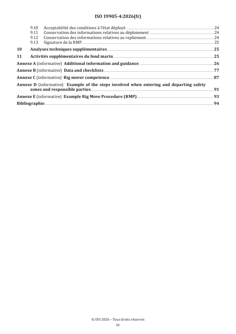
Sommaire Page
Avant-propos .v
Introduction .vi
1 Domaine d'application . 1
2 Références normatives . 1
3 Termes et définitions . 2
4 Symboles et abréviations .12
4.1 Symboles . 12
4.2 Abréviations. 13
5 Considérations générales . 14
5.1 Généralités .14
5.2 Interaction avec la SSA-E .14
5.3 Compétence de l'évaluateur .16
5.4 Planification .16
5.5 Certification du personnel et logistique des déplacements . .16
5.6 Réglementations .16
5.7 Classification de la plate‐forme auto‐élévatrice .16
5.8 Outils analytiques .16
6 Causes, effets et conséquences potentiels des dommages . 17
6.1 Généralités .17
6.2 Causes .17
6.3 Effets .18
6.4 Conséquences .18
7 Limites d'opérabilité .18
8 Données, études et préparation . 19
8.1 Collecte des données .19
8.1.1 Généralités .19
8.1.2 Données relatives au site .19
8.1.3 Données relatives à la plate-forme auto-élévatrice .19
8.2 Adéquation à une configuration relevée . 20
8.2.1 Examen de l'évaluation spécifique au site ‐ mode relevé . 20
8.2.2 Examen des exigences relatives aux opérations en mode relevé . 20
8.3 Recommandations et évaluation du déploiement et du repliement . 20
8.3.1 Généralités . 20
8.3.2 Préparation des recommandations relatives à l'opérabilité . 20
8.4 Appréciation du risque . 20
8.5 Avis opérationnel .21
8.6 Assurance maritime .21
8.7 Gestion du changement . .21
9 Élaboration d'une procédure de déplacement de plate-forme pour le déploiement et le
repliement . .21
9.1 Généralités .21
9.2 Documents de référence . 22
9.3 Contenu général . 22
9.4 Plate‐forme auto‐élévatrice et facteurs spécifiques au déplacement . 23
9.5 Chaîne de commandement et de communication . 23
9.5.1 Chaîne de commandement . 23
9.5.2 Communication des limitations opérationnelles . 23
9.6 Rôles et responsabilités . 23
9.7 Gestion du changement (MOC) . 23
9.8 Phase de confirmation . 23
9.9 Phase d'exécution .24
iii
9.10 Acceptabilité des conditions à l'état déployé .24
9.11 Conservation des informations relatives au déploiement .24
9.12 Conservation des informations relatives au repliement .24
9.13 Signature de la RMP . 25
10 Analyses techniques supplémentaires .25
11 Activités supplémentaires du fond marin .25
Annexe A (informative) Additional information and guidance .26
Annexe B (informative) Data and checklists .77
Annexe C (informative) Rig mover competence .87
Annexe D (informative) Example of the steps involved when entering and departing safety
zones and responsible parties .91
Annexe E (informative) Example Rig Move Procedure (RMP) .93
Bibliographie .94
iv
Avant-propos
L'ISO (Organisation internationale de normalisation) est une fédération mondiale d'organismes nationaux
de normalisation (comités membres de l'ISO). L'élaboration des Normes internationales est en général
confiée aux comités techniques de l'ISO. Chaque comité membre intéressé par une étude a le droit de faire
partie du comité technique créé à cet effet. Les organisations internationales, gouvernementales et non
gouvernementales, en liaison avec l'ISO participent également aux travaux. L'ISO collabore étroitement avec
la Commission électrotechnique internationale (IEC) en ce qui concerne la normalisation électrotechnique.
Les procédures utilisées pour élaborer le présent document et celles destinées à sa mise à jour sont
décrites dans les Directives ISO/IEC, Partie 1. Il convient, en particulier de prendre note des différents
critères d'approbation requis pour les différents types de documents ISO. Le présent document
a été rédigé conformément aux règles de rédaction données dans les Directives ISO/IEC, Partie 2
(voir www.iso.org/directives).
L'attention est appelée sur le fait que certains des éléments du présent document peuvent faire l'objet de
droits de propriété intellectuelle ou de droits analogues. L'ISO ne saurait être tenue pour responsable de ne
pas avoir identifié de tels droits de propriété et averti de leur existence. À la date de publication du présent
document, l'ISO n'avait pas reçu notification qu'un ou plusieurs brevets pouvaient être nécessaires à sa mise
en application. Toutefois, il y a lieu d'avertir les responsables de la mise en application du présent document
que des informations plus récentes sont susceptibles de figurer dans la base de données de brevets,
disponible à l'adresse www.iso.org/brevets. L'ISO ne saurait être tenue pour responsable de ne pas avoir
identifié tout ou partie de tels droits de brevet.
Les appellations commerciales éventuellement mentionnées dans le présent document sont données pour
information, par souci de commodité à l'intention des utilisateurs et ne sauraient constituer un engagement.
Pour une explication de la nature volontaire des normes, la signification des termes et expressions
spécifiques de l'ISO liés à l'évaluation de la conformité, ou pour toute information au sujet de l'adhésion de
l'ISO aux principes de l'Organisation mondiale du commerce (OMC) concernant les obstacles techniques au
commerce (OTC), voir www.iso.org/avant-propos.
Le présent document a été élaboré par le comité technique ISO/TC 67, Industries du pétrole et du gaz, y
compris les énergies à faible teneur en carbone, sous-comité SC 7, Structures en mer.
Une liste de toutes les parties de l'ISO 19905 se trouve sur le site web de l'ISO.
Il convient que l'utilisateur adresse tout retour d'information ou toute question concernant le présent
document à l'organisme national de normalisation de son pays. Une liste exhaustive desdits organismes se
trouve à l'adresse www.iso.org/fr/members.html.
v
Introduction
Les Normes internationales pour les structures en mer élaborées par le TC 67/SC 7 [c'est-à-dire l'ISO 19900,
l'ISO 19901 (toutes les parties), l'ISO 19902, l'ISO 19903, l'ISO 19904-1, l'ISO 19905 (toutes les parties), et
l'ISO 19906] constituent une base commune qui couvre les aspects traitant des exigences de conception et
des évaluations de toutes les structures en mer utilisées dans le secteur de l'énergie dans le monde. Leur
mise en œuvre a pour finalité d'atteindre des niveaux de fiabilité appropriés pour les structures en mer,
quels que soient le type de structure et la nature des matériaux utilisés.
L'intégrité structurale est un concept global qui comprend la modélisation des actions, les analyses
structurales, les règles de conception ou d'évaluation, les aspects liés à la sécurité, la qualité de l'ouvrage,
ainsi que les procédures de contrôle de la qualité et les réglementations nationales, ces divers éléments
étant interdépendants. La modification d'un aspect de la conception ou de l'évaluation pris isolément
peut perturber l'équilibre de la fiabilité inhérent au concept global ou au système structurel global. Les
implications relatives aux modifications doivent être considérées en relation avec la fiabilité d'ensemble de
tous les systèmes structuraux en mer.
Les Normes internationales pour les structures en mer préparées par le TC 67/SC 7 sont élaborées pour
permettre un choix étendu de configurations structurelles, de matériaux et de techniques sans entraver
l'innovation. L'utilisation de ces documents nécessite donc une bonne appréciation en matière d'ingénierie.
Le présent document énonce les principes généraux et les exigences de base pour l'évaluation spécifique au
site du déploiement et du repliement des plates-formes auto-élévatrices mobiles; il est destiné à être utilisé
pour l'évaluation spécifique au site du déploiement et du repliement, et non pour la conception des plates‐
formes auto-élévatrices.
L'évaluation d'une plate‐forme auto‐élévatrice sur un site spécifique comprend normalement deux parties.
1) Évaluer si la plate-forme auto élévatrice peut survivre en mode de fonctionnement relevé.
2) Évaluer si la plate-forme auto élévatrice peut être déployée et repliée en toute sécurité sur le site.
Le point 1 est traité dans l'ISO 19905-1 et le point 2 est traité dans l'ISO 19905-4. Le cas échéant, l'ISO 19905-4
peut être complétée par l'ISO 19905-1 pour les situations où la coque est partiellement élevée entre la surface
de l'eau et la hauteur de la coque en service.
La plupart des informations exigées dans le cadre d'une évaluation conformément à l'ISO 19905-1 (désignée
ici comme une évaluation spécifique au site en mode relevé, ou SSA‐E) sont également requises pour une
évaluation conformément à l'ISO 19905-4 (désignée ici comme une évaluation du déploiement et du
repliement spécifique au site, ou SSA‐I). Cependant, il existe des informations supplémentaires utilisées
dans une SSA-I qu'il est préférable de recueillir en même temps que les données d'une SSA-E. Cette question
est traitée plus en détail en 5.1.
L'évaluation du déploiement et du repliement spécifique au site est normalement exécutée avant le
déploiement ou le repliement d'une plate‐forme auto‐élévatrice en un site spécifique. L'évaluation du
déploiement et du repliement n'a pas pour but de fournir une évaluation complète de la plate-forme auto-
élévatrice. Elle considère par hypothèse que les aspects non traités ici (par exemple, la dérivation de la
résistance des jambes, la condition structurelle de la plate-forme auto-élévatrice) ont été traités en utilisant
d'autres pratiques et d'autres normes ou dans le cadre de l'évaluation des conditions de survie en mode
relevé sur le site en question. Dans certains cas, la conception d'origine de la totalité ou d'une partie de la
structure peut être conforme à d'autres Normes internationales sur les structures en mer élaborées par le
TC 67/SC 7 et, dans certains cas, d'autres pratiques ou d'autres normes peuvent avoir été appliquées.
L'évaluation du déploiement et du repliement spécifique au site a pour but de s'assurer que la plate‐forme
auto-élévatrice et ses fondations ont fait l'objet d'une évaluation adéquate, en prenant en compte les
conséquences d'une défaillance. Il est important d'enregistrer de manière appropriée les résultats d'une
évaluation du déploiement et du repliement spécifique au site et de les communiquer aux personnes qui ont
besoin de connaître les conclusions et les recommandations ou d'agir au vu de celles-ci. D'autres approches
de l'évaluation du déploiement et du repliement spécifique au site peuvent être utilisées, sous réserve qu'il ait
vi
été démontré qu'elles confèrent un niveau de fiabilité structurelle équivalent ou supérieur à celui implicite
dans le présent document.
Les annexes peuvent inclure des termes, définitions et concepts qui diffèrent de ceux inclus dans les parties
obligatoires de la présente partie de l'ISO 19905.
L'Annexe A fournit le contexte et les recommandations relatives à l'utilisation du présent document. La
numérotation des articles et des paragraphes à l'Annexe A est la même que dans le corps de texte afin de
faciliter les références croisées.
L'Annexe B identifie la documentation qu'il convient de recueillir et d'échanger, et fournit des listes de
contrôle des informations et des actions pour les étapes opérationnelles de déploiement et de repliement.
L'Annexe C fournit des recommandations relatives à la compétence du responsable du déplacement de la
plate-forme (le «rig mover»).
L'Annexe D fournit des recommandations relatives aux parties responsables des entrées et sorties des zones
de sécurité.
L'Annexe E fournit un exemple de procédure de déplacement de plate-forme (RMP).
Le présent document est structuré de manière à prendre en compte les problèmes associés à un site
particulier et n'est pas nécessairement organisé de la même manière qu'un propriétaire de plate-forme auto-
élévatrice ou un géomètre élaborerait une procédure de déplacement de plate-forme (qui est normalement
élaborée en termes de sortie d'un site et d'élévation sur le site suivant), voir Figure 0-1.
Figure 0-1 — Alignement des évaluations spécifiques sur plusieurs sites et sur les déplacements de
plates-formes
Les dispositions du présent document forment une approche intégrée pour la SSA-I, qui est destinée à être
utilisée dans sa totalité pour l'évaluation du déploiement et du repliement spécifique au site d'une plate‐
forme auto-élévatrice à jambes indépendantes.
Le présent document a été élaboré en admettant par hypothèse qu'une évaluation spécifique au site pour
les opérations en mode relevé (survie) (SSA-E) est disponible pour le site en question. Il peut être possible
d'élaborer une RMP incomplète avant la finalisation de la SSA‐E.
vii
Norme internationale ISO 19905-4:2026(fr)
Évaluation spécifique au site d'unités mobiles en mer —
Partie 4:
Déploiement et repliement de plates-formes auto élévatrices
sur site
1 Domaine d'application
Le présent document spécifie les exigences et les recommandations pour le déploiement et le repliement
de plates-formes auto-élévatrices à jambes indépendantes destinées à être utilisées dans les industries du
pétrole et du gaz, y compris les énergies à faible teneur en carbone. Il traite de l'évaluation:
a) de l'opération de déploiement, entre le moment où la plate-forme auto-élévatrice pénètre dans la zone
de sécurité définie de la plate‐forme d'accueil ou du site prévu et le moment où elle est élevée jusqu'à la
hauteur de coque en service au-dessus de la marée astronomique la plus basse (LAT) et où elle est prête
pour l'exploitation;
b) de l'opération de repliement, entre le moment où la plate-forme auto-élévatrice est prête à s'abaisser et
le moment où elle quitte la zone de sécurité définie.
NOTE 1 Bien que le présent document concerne les plates-formes auto-élévatrices à jambes indépendantes, de
nombreuses dispositions peuvent être appliquées aux plates-formes auto-élévatrices supportées par un plancher de
stabilité.
Lorsque la plate-forme auto-élévatrice dispose d'une aide à la propulsion ou est auto-propulsée, les
dispositions du présent document relatives au positionnement peuvent être remplacées ou complétées,
selon le cas.
Le présent document exclut le déplacement de la plate-forme auto-élévatrice entre les sites et les opérations
en mode relevé, qui sont respectivement couvertes par la Classe OMI et l'ISO 19905-1.
NOTE 2 Bien que le présent document traite du déploiement et du repliement d'une plate-forme auto-élévatrice sur
un site, les RMP incluent normalement le déplacement de la plate-forme auto-élévatrice entre les sites (voir l'exemple
de RMP dans l'Annexe E).
2 Références normatives
Les documents suivants sont cités dans le texte de sorte qu'ils constituent, pour tout ou partie de leur
contenu, des exigences du présent document. Pour les références datées, seule l'édition citée s'applique. Pour
les références non datées, la dernière édition du document de référence s'applique (y compris les éventuels
amendements).
ISO 19901-8, Industries du pétrole et du gaz y compris les énergies à faible teneur en carbone — Structures en
mer — Partie 8: Investigations des sols en mer
ISO 19901-10, Industries du pétrole et du gaz naturel — Exigences spécifiques relatives aux structures en mer —
Partie 10: Enquêtes géophysiques marines
ISO 19905-1:2023, Industries du pétrole et du gaz, y compris les énergies à faible teneur en carbone — Évaluation
spécifique du site d'unités mobiles en mer — Partie 1: Plateformes auto-élévatrices: Surélévées sur un site
3 Termes et définitions
Pour les besoins du présent document, les termes et définitions suivants s'appliquent.
L'ISO et l'IEC tiennent à jour des bases de données terminologiques destinées à être utilisées en normalisation,
consultables aux adresses suivantes:
— ISO Online browsing platform: disponible à l'adresse https:// www .iso .org/ obp
— IEC Electropedia: disponible à l'adresse https:// www .electropedia .org/
3.1
action
charge extérieure appliquée à la plate-forme auto-élévatrice (3.25) (action directe) ou déformation ou
accélération imposée (action indirecte)
EXEMPLE Une déformation imposée peut être causée par des tolérances de fabrication, un tassement différentiel
ou des variations de température ou d'humidité. Une accélération imposée peut être causée par un séisme.
[SOURCE: ISO 19900:2019, 3.3, modifié — «structure» a été remplacé par «plate‐forme auto‐élévatrice».]
3.2
garde d'air
distance entre le niveau le plus élevé de la surface de l'eau qui se produit au cours de la phase actuelle de
l'opération de déploiement ou de repliement et la base de la coque
Note 1 à l'article: L'ISO 19900 définit la «garde d'air» comme la distance entre le niveau le plus élevé de la surface de
l'eau et la partie exposée la plus basse de la structure primaire du pont, qui n'est pas conçue pour supporter les effets
des actions dues à l'environnement pendant une période de retour définie. Cela diffère de la définition de garde d'air
historiquement utilisée par l'industrie des plates-formes auto-élévatrices. Dans l'ISO 19905-1, la hauteur de la coque
au-dessus de la LAT (3.29) est utilisée pour le cas opérationnel en conditions relevées.
3.3
évaluation
évaluation spécifique au site
évaluation de la stabilité et de l'intégrité structurelle d'une plate-forme auto-élévatrice (3.25) et, le cas
échéant, de son encastrement dans le fond marin ou de son support sur le fond marin vis-à-vis des actions
(3.1) déterminées conformément à des exigences spécifiques
Note 1 à l'article: Les exigences spécifiques sont données dans le présent document.
Note 2 à l'article: Une évaluation peut être limitée à une évaluation des composants ou éléments de la structure qui,
lorsqu'ils sont enlevés ou endommagés, pourraient provoquer la défaillance de la structure entière ou d'une partie
significative de celle‐ci.
[SOURCE: ISO 19905-1:2023, 3.6]
3.4
critères d'évaluation
formulations quantitatives décrivant les conditions à remplir pour chaque situation d'évaluation (3.6)
[SOURCE: ISO 19900:2019, 3.15, modifiée — Suppression de la référence à la «conception».]
3.5
résistance pour l'évaluation
limite de résistance calculée en utilisant des valeurs représentatives (3.46) pondérées des variables de base
(3.10) ou à partir d'expressions pondérées fondées sur des valeurs représentatives (3.46) non pondérées des
variables de base (3.10)
EXEMPLE Les propriétés des matériaux sont des exemples de variables de base pertinentes pour la résistance.
[SOURCE: ISO 19900:2019, 3.12, modifié — «conceptuelle»a été remplacé par «d'évaluation».]
3.6
condition de calcul
ensemble de conditions physiques en fonction duquel la plate-forme auto-élévatrice (3.25) ou ses éléments
sont vérifiés
Note 1 à l'article: Les situations d'évaluation font l'objet d'une vérification par rapport aux critères d'acceptation du
présent document pour démontrer que les états limites (3.28) concernés n'ont pas été dépassés.
[SOURCE: ISO 19900:2019, 3.16, modifié — Suppression de la référence à la «conception» et remplacement
de «structure» par «plate-forme auto-élévatrice». Ajout de la Note 1 à l'article]
3.7
évaluateur
entité effectuant l'évaluation spécifique du site (3.3)
[SOURCE: ISO 19905-1:2023, 3.10]
3.8
remblayage
poids submergé de la totalité du sol qui peut être présent au-dessus du caisson de support (3.59)
Note 1 à l'article: Un remblayage peut apparaître au cours ou après le préchargement (3.38). W désigne le poids
BF,o
submergé du remblayage qui apparaît jusqu'à la réalisation de la réaction de précharge (3.40). W désigne le poids
BF,A
submergé du remblayage qui apparaît après application et maintien de la précharge maximale. W et W peuvent
BF,o BF,A
comprendre le retour (3.9) ou le remplissage (3.24), ou les deux.
[SOURCE: ISO 19905‐1:2023, 3.11, modifié — Dans la note 1 à l'article, la dernière phrase a été supprimée.]
3.9
retour
sol qui s'écoule depuis le dessous du caisson de support (3.59) autour des côtés et jusqu'en haut
Note 1 à l'article: Le retour fait partie du remblayage (3.8).
[SOURCE: ISO 19905-1:2023, 3.12]
3.10
variable de base
variable se rapportant aux grandeurs physiques qui caractérisent les actions (3.1) et les incidences de
l'environnement, les grandeurs géométriques ou les propriétés des matériaux, y compris les propriétés des
sols
Note 1 à l'article: Les variables de base sont généralement des variables aléatoires incertaines ou des processus
aléatoires utilisés dans le calcul ou l'évaluation des valeurs représentatives (3.46) d'actions ou de résistance.
[SOURCE: ISO 19900:2019, 3.7]
3.11
certificat d'approbation
CoA
Certificate of Approval
certificat délivré par la société d'expertise maritime (3.32) après examen de la procédure de déplacement de
la plate-forme (3.48), de la documentation relative aux opérations prévues, des conditions météorologiques,
des prévisions météorologiques et de l'équipement de vérification
Note 1 à l'article: Des CoA distincts peuvent être délivrés pour l'opération de repliement, pour le déplacement de la
plate-forme, pour le déploiement sur site et pour l'opération en mode relevé (en ce qui concerne la capacité à résister
aux conditions de tempête en mode relevé).
3.12
zéro d'une carte marine
CD
point de référence local utilisé pour fixer les profondeurs d'eau sur une carte ou les hauteurs de marée sur
une zone
Note 1 à l'article: En général, le zéro d'une carte marine correspond approximativement au niveau de la marée
astronomique la plus basse (3.29).
Note 2 à l'article: Le zéro d'une carte marine peut différer d'une carte à l'autre et il convient d'être prudent si l'on
compare des sites qui ne figurent pas sur la même carte.
[SOURCE: ISO 19901‐1:2026, 3.2, modifiée — Ajout de la Note 2 à l'article.]
3.13
valeur caractéristique
valeur attribuée à une variable de base (3.10) avec une probabilité donnée
Note 1 à l'article: Dans certaines conditions de calcul, une variable peut avoir deux valeurs caractéristiques, une valeur
haute et une valeur basse.
[SOURCE: ISO 19900:2019, 3.9]
3.14
plan d'urgence
plan visant à mettre en œuvre d'autres opérations si la sécurité ou la productivité est compromise
3.15
zone de sécurité définie
zone de sécurité autour de la plate-forme d'accueil ou de l'emplacement d'exploitation placée sous le contrôle
du responsable d'installation en mer (OIM) de la plate-forme ou de l'emplacement
Note 1 à l'article: La zone s'étend généralement à 500 m de la plate-forme d'accueil ou de l'emplacement d'exploitation,
et la zone peut être appelée zone de 500 m.
3.16
champ
zone générale où la plate-forme auto-élévatrice (3.25) est destinée à fonctionner
Note 1 à l'article: Le champ est une zone générale par opposition au site (3.54) qui est spécifique
[SOURCE: ISO 19905-1:2023, 3.23]
3.17
charge fixe
poids à vide
partie permanente de la plate-forme auto-élévatrice (3.25) comprenant la coque, les jambes et les caissons de
support (3.59), l'appareillage, les équipements d'armement, fixes et mobiles
Note 1 à l'article: Les équipements fixes et mobiles comprennent normalement la structure de l'appareil de forage et
l'équipement associé fixé de manière permanente.
[SOURCE: ISO 19905‐1:2023, 3.24, modifié — Le terme admis «poids à vide» a été ajouté.]
3.18
empreinte au sol
dépression dans le fond océanique qui reste lorsqu'une plate-forme auto-élévatrice (3.25) est enlevée d'un
site
[SOURCE: ISO 19905-1:2023, 3.25]
3.19
fondation
sol et caisson de support (3.59)supportant une jambe de plate-forme auto-élévatrice (3.25)
[SOURCE: ISO 19905-1:2023, 3.26]
3.20
point d'arrêt
point dans le temps au cours duquel les opérations sont interrompues en vue d'une prise de décision
3.21
injection au niveau de la coque
injection lors de l'application d'une flottabilité excessive, créant ainsi une traction excessive avec un
blocage de l'ensemble des jambes, une injection alternée entre les jambes selon les besoins, ou une injection
simultanée sur toutes les jambes, tout en maintenant la coque à un niveau aussi élevé que possible dans les
limites du concepteur et en libérant les jambes aussi près que possible les unes des autres
3.22
erreur humaine
action ou inaction humaine pouvant entraîner un résultat inattendu
3.23
plate-forme auto-élévatrice à jambes indépendantes
unité de plate-forme auto-élévatrice (3.25) comportant des jambes qui peuvent être surélévées et abaissées
indépendamment
[SOURCE: ISO 19905-1:2023, 3.32]
3.24
remplissage
sol au-dessus de la zone plane du caisson de support (3.59) provenant d'un transport de sédiments ou d'un
effondrement de la paroi latérale du trou
Note 1 à l'article: Le remplissage fait partie du remblayage (3.8).
[SOURCE: ISO 19905-1:2023, 3.34]
3.25
plate-forme auto-élévatrice
unité marine mobile comportant une coque flottante et une ou plusieurs jambes qui peuvent être levées et
baissées par rapport à la coque
Note 1 à l'article: Une plate-forme auto-élévatrice atteint son mode de fonctionnement en abaissant la ou les jambes
jusqu'à ce qu'elles viennent prendre appui sur le fond marin, puis en soulevant la coque jusqu'à la hauteur requise.
La majorité des plates-formes auto-élévatrices compte trois jambes ou plus dont chacune peut être déplacée
indépendamment et qui sont supportées dans le fond marin par des caissons de support (3.59).
[SOURCE: ISO 19905-1:2023, 3.36]
3.26
armateur de la plate-forme auto-élévatrice
propriétaire
représentant de la société ou des sociétés possédant la plateforme auto-élévatrice (3.25) ou l'affrétant
Note 1 à l'article: La société d'énergie, l'exploitant (3.37), utilise la plateforme auto-élévatrice sous contrat et n'est
généralement pas l'exploitant ou l'affréteur.
[SOURCE: ISO 19905-1:2023, 3.37]
3.27
descente de jambe
mouvement de jambe vertical prolongé qui peut être contrôlé par le système de levage, de sorte que la coque
puisse être maintenue dans des limites tolérables
3.28
état limite
état au-delà duquel la plate-forme auto-élévatrice (3.25) ne satisfait plus aux critères d'évaluation (3.4)
[SOURCE: ISO 19905‐1:2023, 3.40, modifiée — Les mots «ou un élément de structure» ont été supprimés]
3.29
marée astronomique la plus basse [lowest astronomical tide]
LAT
niveau de marée basse atteint lorsque toutes les composantes harmoniques entraînant les marées sont en
phase
Note 1 à l'article: Les composantes harmoniques sont en phase environ tous les 19 ans, mais ces conditions sont
approchées plusieurs fois par an.
[SOURCE: ISO 19901-1:2026, 3.18]
3.30
assurance maritime
examen secondaire des procédures de déploiement et de repliement en mer
3.31
manuel d'exploitation en mer
manuel d'exploitation en mer
manuel d'exploitation
document approuvé le plus récent qui définit les caractéristiques et les capacités d'exploitation de la plate-
forme auto élévatrice (3.25)
Note 1 à l'article: Il convient que l'évaluateur (3.7) veille à ce que toutes les données de poids fournies soient à jour.
3.32
société d'expertise maritime
MWS (marine warranty survey company)
organisation approuvée par les assureurs pour satisfaire aux exigences de la clause de garantie d'une police
d'assurance maritime
Note 1 à l'article: L'objectif fondamental du MWS est de faire des efforts raisonnables pour s'assurer que les risques
associés à l'opération justifiée (dans ce cas, le déplacement de la plate‐forme) sont ramenés à un niveau acceptable
conformément aux bonnes pratiques de l'industrie. La MWS peut spécifier des recommandations à respecter afin
de réduire autant que possible le risque pour la plate-forme auto-élévatrice assurée pendant toutes les phases du
déplacement et de se conformer aux termes de la garantie.
Note 2 à l'article: La présence d'une MWS n'est pas toujours une exigence de la clause de garantie d'assurance.
3.33
plate-forme auto-élévatrice supportée par un plancher de stabilité
unité de plate-forme auto-élévatrice (3.25) ayant la ou les jambes connectées rigidement par une structure
de fondation de sorte que la ou les jambes sont surélevées et abaissées à l'unisson
[SOURCE: ISO 19905-1:2023, 3.44]
3.34
zone neutre
zone de tirant d'eau de la coque à travers laquelle la charge verticale est inversée entre les jambes et la coque
Note 1 à l'article: La coque et les jambes sont indépendantes l'une de l'autre, étant donné que ni traction ni compression
ne sont appliquées au système de levage.
Note 2 à l'article: La zone peut couvrir une plus grande étendue en présence de vagues.
Note 3 à l'article: À ce tirant d'eau, tout jeu d'engrènement dans le pignon à l'interface crémaillère‐dents peut avoir des
effets néfastes (déroulement et réenroulement des boîtes de vitesses à trains planétaires) même lorsque les freins sont
réglés dans des conditions de houle modérée.
Note 4 à l'article: Les effets d'une flottabilité neutre sont les plus répandus sur les systèmes de levage flottants (c'est‐à‐
dire en provoquant le rebond des unités de levage entre les coussins amortisseurs de choc).
3.35
valeur nominale
valeur attribuée à une variable spécifiée ou déterminée sans faire référence à des statistiques, typiquement
à partir de l'expérience acquise ou de données physiques, ou telle que publiée dans une norme ou un code
reconnu
Note 1 à l'article: Dans certaines situations de conception/d'évaluation, une variable peut avoir deux valeurs nominales,
une valeur haute et une valeur basse.
[SOURCE: ISO 19900:2019, 3.33]
3.36
limites d'opérabilité
conditions prédéfinies (par exemple, océano‐météorologiques, mouvements, charges) à l'extérieur desquelles
il est nécessaire de suspendre les opérations de déploiement ou de repliement
3.37
exploitant
représentant de la (des) société(s) recevant à bail le site
Note 1 à l'article: L'exploitant est normalement la société pétrolière agissant pour le compte des co-licenciés.
[SOURCE: ISO 19900:2019, 3.35, modifié — Suppression de la Note 2 à l'article.]
3.38
préchargement
installation et enfouissement des caissons de support (3.59) par chargement vertical du sol au-dessous d'un
caisson de support (3.59) de jambe de plate-forme auto-élévatrice dont l'objectif est de garantir une capacité
de fondation suffisante dans le cas des situations d'évaluation (3.6), jusqu'au moment où la charge maximale
est appliquée et maintenue
Note 1 à l'article: Alors que les plates-formes auto-élévatrices à trois jambes effectuent un préchargement en
embarquant des ballasts d'eau à bord, les plates-formes auto-élévatrices ayant quatre jambes ou plus réalisent
habituellement le préchargement de fondation en faisant porter le poids de la coque sur les paires de jambes tour à
tour. Cette procédure est connue comme étant le pré-battage et ne requiert généralement pas l'ajout de ballast d'eau.
Pour les besoins du présent document, aucune distinction n'est faite entre le préchargement et le pré-battage.
[SOURCE: ISO 19905-1:2023, 3.55]
3.39
garde d'air de préchargement
distance entre la ligne de base de la coque et le niveau de l'eau au repos en un point dans le temps au cours
du préchargement (3.38)
Note 1 à l'article: L'ISO 19900 définit la «garde d'air» comme la distance entre le niveau le plus élevé de la surface de
l'eau et la partie exposée la plus basse de la structure primaire du pont, qui n'est pas conçue pour supporter les effets
des actions dues à l'environnement pendant une période de retour définie. Cela diffère de la définition historiquement
utilisée par l'industrie des plates-formes auto-élévatrices. Dans l'ISO 19905-1 et dans le présent document, la hauteur
de la coque au-dessus de la LAT (3.29) est utilisée pour le cas opérationnel en conditions relevées.
3.40
réaction de préchargement
réaction verticale maximale sous un caisson de support (3.59), V , supportant le poids en eau de la plate-
Lo
forme auto-élévatrice (3.25) au cours de la totalité de l'opération de préchargement (3.38)
Note 1 à l'article: Le poids en eau comprend: le poids complet de la coque, des charges variables (3.64) et des ballasts
de préchargement, plus les jambes et les caissons de support (3.59) et toute l'eau contenue, diminué de la flottabilité
dans l'eau de toute partie immergée de la coque, des jambes et des caissons de support (calculée à partir de leurs
dimensions externes). La flottabilité dans le sol et le poids de tout le remblayage (3.8) du sol au-dessus du caisson de
support sont négligés. Il est nécessaire de prendre des précautions lorsque l'on prend en compte l'eau contenue dans le
caisson de support (dans certains cas, celle-ci peut être incluse dans le poids de la jambe citée).
Note 2 à l'article: Il s'agit de la réaction maximale sur un caisson de support (3.59), V , qui serait obtenue au cours du
Lo
préchargement (3.38) si la plate‐forme auto‐élévatrice était installée sur une fondation infiniment rigide.
Note 3 à l'article: V est un paramètre clé dans l'analyse géotechnique des fondations à jambes indépendantes. L
...