

ISO 19901-7:2026
(Main)Specific requirements for offshore structures — Part 7: Stationkeeping systems for floating offshore structures and mobile offshore units
- Abstract
This document specifies methodologies for: the design, analysis and evaluation of stationkeeping systems for floating offshore structures; the assessment of stationkeeping systems for site-specific applications of mobile offshore units and construction units. Originally developed for floating structures used in the oil and gas industry, this document is now also used in the renewable energy sector. The extent of application of this document to floating structures used in other industries is at the discretion of the relevant standard entity and its users. For example, IEC 61400-3-2 for floating wind applies this document to determine stationkeeping system responses while incorporating its own load conditions, safety factors, and environmental return periods. This document is applicable to the following types of stationkeeping systems, which are either covered directly in this document or through reference to other guidelines: spread mooring systems; single point mooring systems; dynamic positioning systems; thruster-assisted mooring systems. This document is not applicable to: stationkeeping systems which do not have redundancy against failure of any single component, e.g., single anchor leg moorings (SALMs); stationkeeping systems which use any means other than mooring lines or thrusters such as tower soft yoke systems, or tension leg platforms (TLPs) that use tendons. The requirements for this document address spread mooring systems and single point mooring systems with mooring lines composed of steel chain, steel wire or synthetic fibre rope. This document is applicable to all aspects of the life cycle of mooring systems. It includes requirements relating to the selection of mooring components, mooring system configuration and performance, components design, installation, post-installation survey, and as-installed assessments as needed for mooring integrity management. For mooring systems deployed in ice-prone environments, additional requirements in ISO 19906 apply.
- Status
- Published
- Publication Date
- 13-Jul-2026
- Technical Committee
- ISO/TC 67/SC 7 - Offshore structures
- Drafting Committee
- ISO/TC 67/SC 7 - Offshore structures
- Current Stage
- 6060 - International Standard published
- Start Date
- 14-Jul-2026
- Due Date
- 11-May-2026
- Completion Date
- 14-Jul-2026
Buy Documents
ISO 19901-7:2026 - Specific requirements for offshore structures — Part 7: Stationkeeping systems for floating offshore structures and mobile offshore units
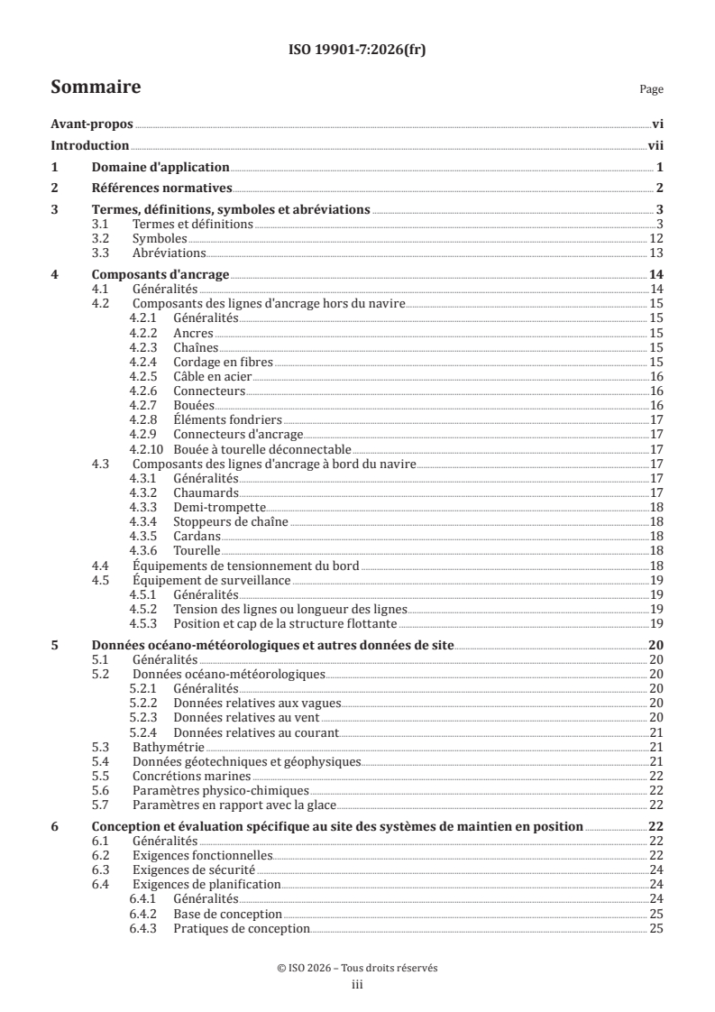
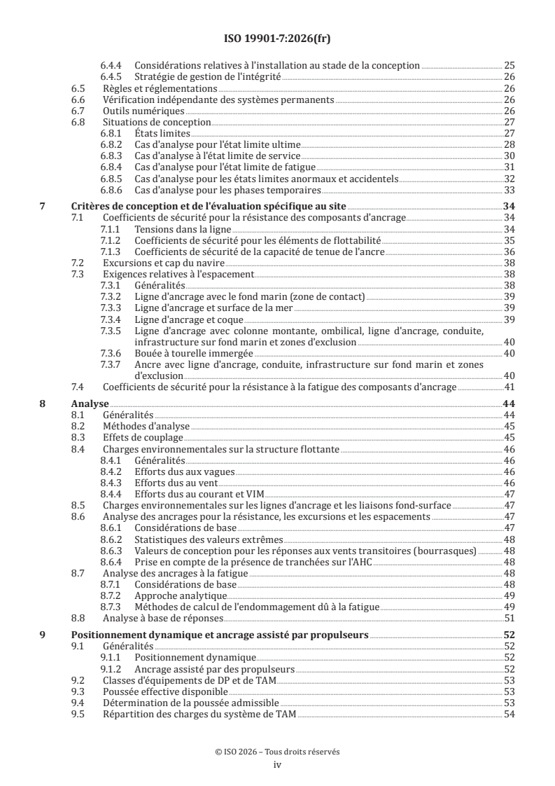
ISO 19901-7:2026 - Exigences spécifiques relatives aux structures en mer — Partie 7: Systèmes de maintien en position des structures en mer flottantes et des unités mobiles en mer
ISO 19901-7:2026 is an International Standard from ISO on stationkeeping systems for floating offshore structures and mobile offshore units. It specifies methodologies for designing, analysing, evaluating, and assessing mooring and stationkeeping systems used to keep a floating structure on location or on heading within defined limits. It is written for offshore engineers, operators, assessors, and others who need to define, verify, install, inspect, and maintain these systems in practice.
What does ISO 19901-7:2026 specify?
ISO 19901-7:2026 specifies the framework for stationkeeping systems across the full life cycle, from site data and design basis through installation, survey, inspection, and integrity management. It focuses on floating offshore structures and site-specific applications of mobile offshore units and construction units.
The document applies to spread mooring systems, single point mooring systems, dynamic positioning systems, and thruster-assisted mooring systems. It is written mainly for spread mooring and single point mooring systems with steel chain, steel wire, or synthetic fibre rope, while also covering DP and TAM topics in dedicated clauses.
The standard is organized into clauses on mooring hardware, site data, design and site-specific assessment, criteria, analysis, DP and TAM, installation and as-installed survey, and integrity management, survey, inspection, and monitoring. Annex A gives additional information and guidance, and Annex B gives regional requirements and supporting information.
| Annex | What it covers |
|---|---|
| Annex A | Additional information, guidance, system descriptions, figures, and worked technical commentary |
| Annex B | Regional requirements and supporting information, including Norway, Canada, and USA Gulf of Mexico material |
What are the key requirements of ISO 19901-7:2026?
ISO 19901-7:2026 requires the stationkeeping system to be planned, designed, constructed, operated, and assessed so that it meets its functional requirements through its whole life. In practice, that means the designer and operator have to link the system design to the actual site, vessel, operating mode, and service life.
Functional intent and limits - Clause 6.2 says stationkeeping must restrict horizontal excursion and provide directional control when orientation matters. The operator sets the performance standards, and these limits have to reflect safety, environment, risers, topsides equipment, and nearby installations.
Safety and risk basis - Clause 6.3 requires safe design, safe operating procedures, and risk assessment. The design has to account for likely environmental and external actions and for accidental events that could threaten people, the structure, or the environment.
Site data for design - Clause 5 requires metocean, bathymetry, geotechnical, geophysical, marine growth, physicochemical, and ice-related data as relevant. This matters because mooring loads, anchor capacity, corrosion, and clearance checks depend on the actual site conditions, not just general assumptions.
Design situations and limit states - Clause 6.8 structures the assessment around ultimate limit state (ULS), serviceability limit state (SLS), fatigue limit state (FLS), abnormal and accidental cases, and temporary phases. This tells the reader which conditions must be checked and why - strength, offset, fatigue, upset conditions, and storm-safe or installation phases all need separate treatment.
Design criteria and clearances - Clause 7 sets the checks for component strength, vessel offsets and heading, clearances, and fatigue resistance. In practice, the operator must define offset and heading limits, while the designer must show that mooring lines, hull, seabed, risers, umbilicals, pipelines, and exclusion zones are kept clear where required.
Analysis method - Clause 8 requires mooring analysis for the design situations in Clause 6 and comparison with the criteria in Clause 7. The standard uses line dynamic analysis, allows frequency-domain, time-domain, or combined methods, and says quasi-static methods are not for final design of permanent systems or final site-specific assessment of MOU mooring systems.
DP and TAM reliability - Clause 9 requires redundancy, FMEA (failure modes and effects analysis), thrust determination, equipment class assignment, proving trials, and capability checks. The practical effect is that a DP or TAM system has to be shown able to hold station after the worst relevant single failure, with trained personnel and ongoing test and maintenance control.
Installation and integrity management - Clauses 10 and 11 require installation tolerances, traceability, as-installed survey, a mooring integrity management (MIM) program, inspection, conformity assessment, and monitoring. This matters because the as-built condition often drives the real capacity of the system, and the standard ties design assumptions to what was actually installed and how it is maintained.
What terms does ISO 19901-7:2026 define?
ISO 19901-7:2026 defines the vocabulary used to specify stationkeeping performance and assessment. The following terms are especially important for reading the standard correctly.
- Dynamic positioning (DP) - a stationkeeping technique that uses automatically controlled on-board thrusters to counter mean and slowly varying actions.
- Thruster-assisted mooring (TAM) - a stationkeeping arrangement that combines mooring with thrusters so that the thrusters share part of the stationkeeping duty.
- Active stationkeeping system - a system that can change thruster use, line length, pretension, draught, winching, or disconnection to maintain position.
- Damaged condition - the state of the stationkeeping system with a weakened or missing mooring line, thruster failure, or a combination of both.
- Design situation - the defined set of physical conditions used to verify the structure or its components, such as environment, load condition, water depth, and intact or damaged configuration.
- Fitness-for-service assessment - an engineering evaluation used to show that a structure or component that has deviated from its design basis still meets defined integrity and performance requirements.
- End-of-life break strength (ELBS) - the break strength of a mooring component at the end of its design service life after degradation has been taken into account.
- Weathervaning - the passive change of heading of a floating structure in response to changing environmental actions.
Who uses ISO 19901-7:2026?
ISO 19901-7:2026 is used by offshore project teams that specify, design, check, install, inspect, and maintain mooring and stationkeeping systems. It is relevant to the oil and gas industry, and the scope also notes use in the renewable energy sector, including floating wind applications that apply its response methods alongside their own load and safety rules.
Typical users include mooring engineers, naval architects, offshore structural engineers, geotechnical engineers, marine operations teams, integrity managers, operators, classification and verification bodies, and regulators. It is also relevant to buyers and contractors who need to define performance standards, manufacturing quality plans, installation tolerances, test loads, and inspection obligations.
What changed in ISO 19901-7:2026 from the previous edition?
ISO 19901-7:2026 is the third edition and cancels and replaces ISO 19901-7:2013. The foreword says it has been technically revised.
The main stated changes are:
- addition of requirements for a mooring integrity management system
- stronger emphasis on defining the operator's expectations for the performance standard
- inclusion of fibre ropes alongside chain and steel wire ropes
- alignment of anchor geotechnical design text with ISO 19901-4
- added guidance on OPB (out of plane bending) fatigue and squall design cases
Which standards are used with ISO 19901-7:2026?
ISO 19901-7:2026 cites several standards and industry documents that supply inputs, methods, or companion requirements.
- ISO 19900, ISO 19901-1, ISO 19901-4, ISO 19901-6, ISO 19901-8, ISO 19901-10, ISO 19904-1, ISO 19905-3, ISO 19906 - provide the wider offshore structure framework, metocean design basis, geotechnical design, marine operations, marine soil and geophysical investigation, floating structure and mobile unit context, and Arctic requirements.
- ISO 18692-1 and ISO 20438 - support fibre rope and offshore mooring chain requirements.
- ISO 31000 - supports the risk management approach used for stationkeeping decisions and DP/TAM operations.
- IMO MSC.1/Circ.1580 and MTS DP operations guidance - support DP system failure analysis and operating practice.
- IACS UR W22, API RP 2I, API RP 2MIM, API SPEC 9A, ASME Section VIII Division 1, DNV-OS-E301, DNV-RP-E301, DNV-RP-E302, DNV-RP-E303 - provide class, inspection, mooring integrity, wire rope, pressure equipment, and anchor design guidance used alongside the standard.
What does the ISO 19901-7:2026 document contain?
ISO 19901-7:2026 contains technical clauses on mooring hardware, metocean and site data, design and site-specific assessment, design criteria, analysis, DP and TAM, installation, as-installed survey, and integrity management. Clause 4 describes the main hardware from anchors to on-vessel tensioning equipment and monitoring devices, while Clause 5 sets the site data that feed the design.
Clause 6 and Clause 7 give the main design logic, including limit states, strength factors, offset limits, clearance checks, and fatigue resistance. Clause 8 sets out analysis approaches, including frequency-domain, time-domain, and response-based analysis, and Clause 9 covers DP and TAM redundancy, thrust, FMEA, and capability assessment.
Clause 10 deals with constructability, installation tolerances, traceability records, test loading, and as-installed surveys. Clause 11 covers mooring integrity management, inspection programmes, conformity assessment, and monitoring of position, heading, and line failure. Annex A adds figures, component descriptions, guidance, and examples such as spread mooring, internal and external turret systems, disconnectable turret buoy systems, CALM, and SALM arrangements, while Annex B gives regional requirements used for Norway, Canada, and the USA Gulf of Mexico.
Relations
- Effective Date
- 12-Feb-2026
- Effective Date
- 27-Aug-2022
- Effective Date
- 13-Aug-2022
Buy Documents
ISO 19901-7:2026 - Specific requirements for offshore structures — Part 7: Stationkeeping systems for floating offshore structures and mobile offshore units
ISO 19901-7:2026 - Exigences spécifiques relatives aux structures en mer — Partie 7: Systèmes de maintien en position des structures en mer flottantes et des unités mobiles en mer
Get Certified
Connect with accredited certification bodies for this standard

Element Materials Technology
Materials testing and product certification.

ABS Group Brazil
ABS Group certification services in Brazil.

ABS Quality Evaluations Inc.
American Bureau of Shipping quality certification.
Sponsored listings
Frequently Asked Questions
ISO 19901-7:2026 is a standard published by the International Organization for Standardization (ISO). Its full title is "Specific requirements for offshore structures — Part 7: Stationkeeping systems for floating offshore structures and mobile offshore units". This standard covers: This document specifies methodologies for: the design, analysis and evaluation of stationkeeping systems for floating offshore structures; the assessment of stationkeeping systems for site-specific applications of mobile offshore units and construction units. Originally developed for floating structures used in the oil and gas industry, this document is now also used in the renewable energy sector. The extent of application of this document to floating structures used in other industries is at the discretion of the relevant standard entity and its users. For example, IEC 61400-3-2 for floating wind applies this document to determine stationkeeping system responses while incorporating its own load conditions, safety factors, and environmental return periods. This document is applicable to the following types of stationkeeping systems, which are either covered directly in this document or through reference to other guidelines: spread mooring systems; single point mooring systems; dynamic positioning systems; thruster-assisted mooring systems. This document is not applicable to: stationkeeping systems which do not have redundancy against failure of any single component, e.g., single anchor leg moorings (SALMs); stationkeeping systems which use any means other than mooring lines or thrusters such as tower soft yoke systems, or tension leg platforms (TLPs) that use tendons. The requirements for this document address spread mooring systems and single point mooring systems with mooring lines composed of steel chain, steel wire or synthetic fibre rope. This document is applicable to all aspects of the life cycle of mooring systems. It includes requirements relating to the selection of mooring components, mooring system configuration and performance, components design, installation, post-installation survey, and as-installed assessments as needed for mooring integrity management. For mooring systems deployed in ice-prone environments, additional requirements in ISO 19906 apply.
This document specifies methodologies for: the design, analysis and evaluation of stationkeeping systems for floating offshore structures; the assessment of stationkeeping systems for site-specific applications of mobile offshore units and construction units. Originally developed for floating structures used in the oil and gas industry, this document is now also used in the renewable energy sector. The extent of application of this document to floating structures used in other industries is at the discretion of the relevant standard entity and its users. For example, IEC 61400-3-2 for floating wind applies this document to determine stationkeeping system responses while incorporating its own load conditions, safety factors, and environmental return periods. This document is applicable to the following types of stationkeeping systems, which are either covered directly in this document or through reference to other guidelines: spread mooring systems; single point mooring systems; dynamic positioning systems; thruster-assisted mooring systems. This document is not applicable to: stationkeeping systems which do not have redundancy against failure of any single component, e.g., single anchor leg moorings (SALMs); stationkeeping systems which use any means other than mooring lines or thrusters such as tower soft yoke systems, or tension leg platforms (TLPs) that use tendons. The requirements for this document address spread mooring systems and single point mooring systems with mooring lines composed of steel chain, steel wire or synthetic fibre rope. This document is applicable to all aspects of the life cycle of mooring systems. It includes requirements relating to the selection of mooring components, mooring system configuration and performance, components design, installation, post-installation survey, and as-installed assessments as needed for mooring integrity management. For mooring systems deployed in ice-prone environments, additional requirements in ISO 19906 apply.
ISO 19901-7:2026 is classified under the following ICS (International Classification for Standards) categories: 75.180.10 - Exploratory, drilling and extraction equipment. The ICS classification helps identify the subject area and facilitates finding related standards.
ISO 19901-7:2026 has the following relationships with other standards: It is inter standard links to EN ISO 19901-7:2026, ISO 23646:2022, ISO 19901-7:2013. Understanding these relationships helps ensure you are using the most current and applicable version of the standard.
ISO 19901-7:2026 is available in PDF format for immediate download after purchase. The document can be added to your cart and obtained through the secure checkout process. Digital delivery ensures instant access to the complete standard document.
Standards Content (Sample)
International
Standard
ISO 19901-7
Third edition
Specific requirements for offshore
2026-07
structures —
Part 7:
Stationkeeping systems for floating
offshore structures and mobile
offshore units
Exigences spécifiques relatives aux structures en mer —
Partie 7: Systèmes de maintien en position des structures en mer
flottantes et des unités mobiles en mer
Reference number
© ISO 2026
All rights reserved. Unless otherwise specified, or required in the context of its implementation, no part of this publication may
be reproduced or utilized otherwise in any form or by any means, electronic or mechanical, including photocopying, or posting on
the internet or an intranet, without prior written permission. Permission can be requested from either ISO at the address below
or ISO’s member body in the country of the requester.
ISO copyright office
CP 401 • Ch. de Blandonnet 8
CH-1214 Vernier, Geneva
Phone: +41 22 749 01 11
Email: copyright@iso.org
Website: www.iso.org
Published in Switzerland
ii
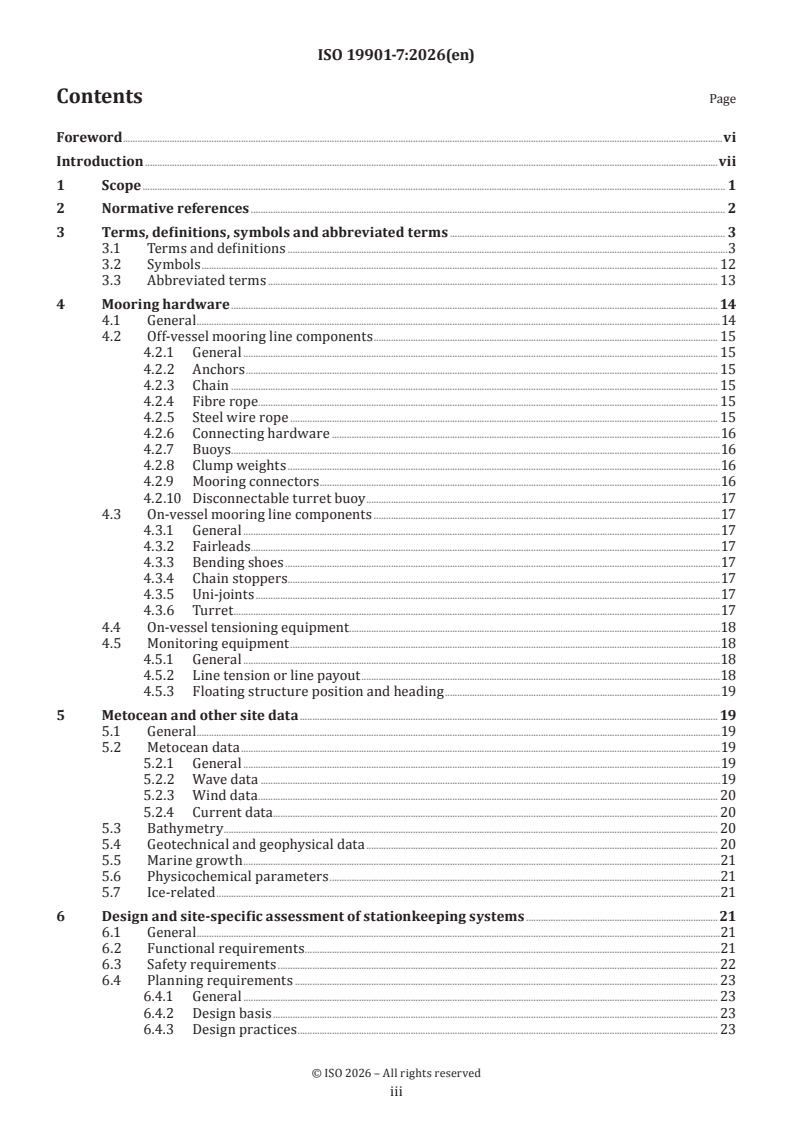
Contents Page
Foreword .vi
Introduction .vii
1 Scope . 1
2 Normative references . 2
3 Terms, definitions, symbols and abbreviated terms .3
3.1 Terms and definitions .3
3.2 Symbols . 12
3.3 Abbreviated terms . 13
4 Mooring hardware . 14
4.1 General .14
4.2 Off-vessel mooring line components . 15
4.2.1 General . 15
4.2.2 Anchors . 15
4.2.3 Chain . 15
4.2.4 Fibre rope. 15
4.2.5 Steel wire rope . 15
4.2.6 Connecting hardware .16
4.2.7 Buoys . .16
4.2.8 Clump weights .16
4.2.9 Mooring connectors . .16
4.2.10 Disconnectable turret buoy .17
4.3 On-vessel mooring line components .17
4.3.1 General .17
4.3.2 Fairleads . .17
4.3.3 Bending shoes .17
4.3.4 Chain stoppers .17
4.3.5 Uni-joints .17
4.3.6 Turret .17
4.4 On-vessel tensioning equipment .18
4.5 Monitoring equipment .18
4.5.1 General .18
4.5.2 Line tension or line payout .18
4.5.3 Floating structure position and heading .19
5 Metocean and other site data . 19
5.1 General .19
5.2 Metocean data .19
5.2.1 General .19
5.2.2 Wave data .19
5.2.3 Wind data . 20
5.2.4 Current data. 20
5.3 Bathymetry . 20
5.4 Geotechnical and geophysical data . 20
5.5 Marine growth .21
5.6 Physicochemical parameters .21
5.7 Ice-related .21
6 Design and site-specific assessment of stationkeeping systems .21
6.1 General .21
6.2 Functional requirements .21
6.3 Safety requirements . 22
6.4 Planning requirements . 23
6.4.1 General . 23
6.4.2 Design basis . 23
6.4.3 Design practices . 23
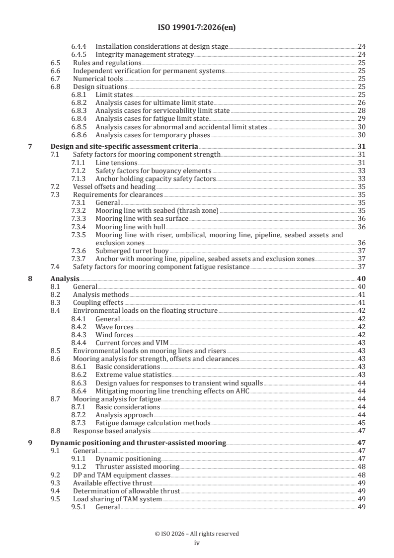
iii
6.4.4 Installation considerations at design stage .24
6.4.5 Integrity management strategy .24
6.5 Rules and regulations . 25
6.6 Independent verification for permanent systems . 25
6.7 Numerical tools . 25
6.8 Design situations . 25
6.8.1 Limit states . 25
6.8.2 Analysis cases for ultimate limit state . 26
6.8.3 Analysis cases for serviceability limit state . 28
6.8.4 Analysis cases for fatigue limit state. 29
6.8.5 Analysis cases for abnormal and accidental limit states . 30
6.8.6 Analysis cases for temporary phases . 30
7 Design and site-specific assessment criteria .31
7.1 Safety factors for mooring component strength .31
7.1.1 Line tensions .31
7.1.2 Safety factors for buoyancy elements . 33
7.1.3 Anchor holding capacity safety factors . 33
7.2 Vessel offsets and heading . 35
7.3 Requirements for clearances . 35
7.3.1 General . 35
7.3.2 Mooring line with seabed (thrash zone) . 35
7.3.3 Mooring line with sea surface . 36
7.3.4 Mooring line with hull . 36
7.3.5 Mooring line with riser, umbilical, mooring line, pipeline, seabed assets and
exclusion zones . 36
7.3.6 Submerged turret buoy .37
7.3.7 Anchor with mooring line, pipeline, seabed assets and exclusion zones .37
7.4 Safety factors for mooring component fatigue resistance .37
8 Analysis . .40
8.1 General . 40
8.2 Analysis methods .41
8.3 Coupling effects .41
8.4 Environmental loads on the floating structure .42
8.4.1 General .42
8.4.2 Wave forces .42
8.4.3 Wind forces .42
8.4.4 Current forces and VIM .43
8.5 Environmental loads on mooring lines and risers .43
8.6 Mooring analysis for strength, offsets and clearances .43
8.6.1 Basic considerations .43
8.6.2 Extreme value statistics .43
8.6.3 Design values for responses to transient wind squalls . 44
8.6.4 Mitigating mooring line trenching effects on AHC . 44
8.7 Mooring analysis for fatigue. 44
8.7.1 Basic considerations . 44
8.7.2 Analysis approach . 44
8.7.3 Fatigue damage calculation methods .45
8.8 Response based analysis .47
9 Dynamic positioning and thruster-assisted mooring. 47
9.1 General .47
9.1.1 Dynamic positioning .47
9.1.2 Thruster assisted mooring. 48
9.2 DP and TAM equipment classes . 48
9.3 Available effective thrust . 49
9.4 Determination of allowable thrust . 49
9.5 Load sharing of TAM system . 49
9.5.1 General . 49
iv
9.5.2 Mean load reduction method . 49
9.5.3 Weathervaning structures . 50
9.5.4 System dynamic analysis . 50
9.6 Failure mode and effects analysis . 50
9.7 Design, test and maintenance .51
9.8 Operating personnel .51
9.9 Determination of stationkeeping capability .51
10 Installation, test load and as-installed survey . 51
10.1 General .51
10.2 Installation considerations and storm-safe criteria .52
10.3 Mooring line handling and installation procedure .52
10.4 Test loading requirements . 53
10.4.1 General . 53
10.4.2 Anchor test load for permanent mooring systems . 53
10.4.3 Anchor test load for mobile mooring systems . 53
10.5 Installation tolerances . 53
10.6 Traceability records . 54
10.7 As-installed survey and establishment of as-installed capacity . 54
11 Integrity management, survey and inspection, and monitoring .55
11.1 Integrity management . 55
11.2 Surveys and inspections . 55
11.2.1 In-service inspection program . 55
11.2.2 As-built inspection . 55
11.2.3 Annual survey . 55
11.2.4 5-year survey . 56
11.3 Conformity assessment .57
11.4 Monitoring . 58
11.4.1 Position and heading monitoring . 58
11.4.2 Line failure detection . 58
Annex A (informative) Additional information and guidance .59
Annex B (normative) Regional requirements and supporting information .140
Bibliography .185
v
Foreword
ISO (the International Organization for Standardization) is a worldwide federation of national standards
bodies (ISO member bodies). The work of preparing International Standards is normally carried out through
ISO technical committees. Each member body interested in a subject for which a technical committee
has been established has the right to be represented on that committee. International organizations,
governmental and non-governmental, in liaison with ISO, also take part in the work. ISO collaborates closely
with the International Electrotechnical Commission (IEC) on all matters of electrotechnical standardization.
The procedures used to develop this document and those intended for its further maintenance are described
in the ISO/IEC Directives, Part 1. In particular, the different approval criteria needed for the different types
of ISO document should be noted. This document was drafted in accordance with the editorial rules of the
ISO/IEC Directives, Part 2 (see www.iso.org/directives).
ISO draws attention to the possibility that the implementation of this document may involve the use of (a)
patent(s). ISO takes no position concerning the evidence, validity or applicability of any claimed patent
rights in respect thereof. As of the date of publication of this document, ISO had not received notice of (a)
patent(s) which may be required to implement this document. However, implementers are cautioned that
this may not represent the latest information, which may be obtained from the patent database available at
www.iso.org/patents. ISO shall not be held responsible for identifying any or all such patent rights.
Any trade name used in this document is information given for the convenience of users and does not
constitute an endorsement.
For an explanation of the voluntary nature of standards, the meaning of ISO specific terms and expressions
related to conformity assessment, as well as information about ISO's adherence to the World Trade
Organization (WTO) principles in the Technical Barriers to Trade (TBT), see www.iso.org/iso/foreword.html.
This document was prepared by Technical Committee ISO/TC 67, Oil and gas industries including lower
carbon energy, Subcommittee SC 7, Offshore structures, in collaboration with the European Committee for
Standardization (CEN) Technical Committee CEN/TC 12, Oil and gas industries including lower carbon energy,
in accordance with the Agreement on technical cooperation between ISO and CEN (Vienna Agreement).
This third edition cancels and replaces the second edition (ISO 19901-7:2013), which has been technically
revised.
The main changes are as follows:
— addition of requirements for a mooring integrity management system;
— emphasis on the definition of the operator's expectations on the performance standard;
— inclusion of fibre ropes as a standard material such as chain and steel wire ropes;
— alignment of text relating to the geotechnical design of anchors with ISO 19901-4;
— inclusion of guidance on OPB (out of plane bending) fatigue and squall design cases.
A list of all parts in the ISO 19901 series can be found on the ISO website.
Any feedback or questions on this document should be directed to the user’s national standards body. A
complete listing of these bodies can be found at www.iso.org/members.html.
vi
Introduction
The International Standards on offshore structures prepared by TC 67 (i.e. ISO 19900, the ISO 19901 series,
ISO 19902, ISO 19903, ISO 19904-1, the ISO 19905 series, ISO 19906) constitute a common basis covering
those aspects that address design requirements and assessments of offshore structures used by the oil and
gas industries worldwide. The intention in their application is to achieve reliability levels appropriate for
manned and unmanned offshore structures, irrespective type of structure and the nature or combination of
materials used.
It is important to recognize that structural integrity is a concept comprised of models that describe actions,
structural analyses, design rules, safety elements, workmanship, quality control procedures and national
requirements, all of which are mutually dependent. The modification of one aspect of design in isolation
can disturb the balance of reliability inherent in the overall design or structural system. The implications
involved in modifications therefore should be considered in relation to the overall reliability of all offshore
structural systems.
The International Standards on offshore structures prepared by TC 67 are intended to provide a wide
breadth of choice for structural configurations, materials and techniques without hindering innovation.
Informed engineering judgement is therefore necessary in the use of these International Standards.
This document was developed in response to the worldwide offshore industry’s demand for a coherent and
consistent definition of methodologies to analyse, design and evaluate stationkeeping systems used for
floating energy production platforms (with and without storage) of various types (e.g. semi-submersibles,
spar platforms, ship-shaped structures) and to assess site-specific applications of mobile offshore units
(such as mobile offshore drilling units and flotels) and construction units (such as heavy lift vessels and
pipelay units).
This document assumes that permanently moored hydrocarbon production systems that are equipped
with stationkeeping systems as a minimum have the ability to both shut-in wells and the facility in case of
emergency (e.g. emergency shut-down valves on the seabed), otherwise the consequence of mooring failure
can be significantly different.
Stationkeeping is a generic term covering systems for keeping a floating structure, which is under the
constant influence of external actions, either at a pre-defined location or at a pre-defined heading or both
with limited excursions. Stationkeeping systems resist external actions by means of any of the following:
— mooring systems (e.g. spread mooring systems or single point mooring systems);
— dynamic positioning systems (generally consisting of thrusters)
— a combination of mooring system and thrusters (thruster assisted mooring systems).
The external actions generally consist of wind, wave, current and ice actions on the floating structure,
mooring and risers.
The procedures for the design of permanent or site-specific assessment of mobile mooring systems specified
in this document are based on a deterministic approach where mooring system responses (such as line
tensions, vessel offsets, and anchor loads) are evaluated for a design environment defined by an annual
probability of exceedance or return period. Mooring system responses are then checked against specified
requirements for mooring strength, offsets and orientation, clearances, anchor capacity, fatigue resistance,
etc. The minimum specified requirements are defined either in this document or by the operator if more
stringent.
NOTE Stationkeeping systems designed based on this deterministic approach can have differing levels of
reliability.
For moored structures (vessels), system responses are calculated and compared to minimum specified
requirements for:
— Ultimate limit states (ULS): mooring component strength. Vessel offset, orientation, and clearance
constraints. Herein the ULS includes both intact and single failure condition for stationkeeping systems.
vii
— Serviceability limit states (SLS): vessel offset, orientation, and clearance constraints. For mooring
components this includes clearances with the vessel, risers, umbilicals, seabed, water surface, field
infrastructure, exclusion zones, etc.
— Fatigue limit states (FLS) : cumulative mooring component fatigue damage.
— Accidental and abnormal limit state (ALS): no criteria are given for accidental or abnormal limit state
which are left to operator decision or local authorities requirements.
The methodology described in this document identifies a set of coherent analysis techniques that, combined
with an understanding of the site-specific metocean conditions, the characteristics of the floating structure
under consideration, and other factors, can be used to determine the adequacy of the stationkeeping system
to meet the functional requirements specified in this document.
Descriptions of characteristics and typical components found in these systems are given in Annex A.
Some background to, and guidance on, the use of this document is provided in Annex A. The clause numbering
in Annex A is the same as in the main text to facilitate cross-referencing.
Regional information, where available, is provided in Annex B.
viii
International Standard ISO 19901-7:2026(en)
Specific requirements for offshore structures —
Part 7:
Stationkeeping systems for floating offshore structures and
mobile offshore units
1 Scope
This document specifies methodologies for:
a) the design, analysis and evaluation of stationkeeping systems for floating offshore structures;
b) the assessment of stationkeeping systems for site-specific applications of mobile offshore units and
construction units.
Originally developed for floating structures used in the oil and gas industry, this document is now also used
in the renewable energy sector. The extent of application of this document to floating structures used in
other industries is at the discretion of the relevant standard entity and its users. For example, IEC 61400-3-2
for floating wind applies this document to determine stationkeeping system responses while incorporating
its own load conditions, safety factors, and environmental return periods.
This document is applicable to the following types of stationkeeping systems, which are either covered
directly in this document or through reference to other guidelines:
— spread mooring systems;
— single point mooring systems;
— dynamic positioning systems;
— thruster-assisted mooring systems.
This document is not applicable to:
— stationkeeping systems which do not have redundancy against failure of any single component, e.g.,
single anchor leg moorings (SALMs);
— stationkeeping systems which use any means other than mooring lines or thrusters such as tower soft
yoke systems, or tension leg platforms (TLPs) that use tendons.
The requirements for this document address spread mooring systems and single point mooring systems
with mooring lines composed of steel chain, steel wire or synthetic fibre rope.
This document is applicable to all aspects of the life cycle of mooring systems. It includes requirements
relating to the selection of mooring components, mooring system configuration and performance,
components design, installation, post-installation survey, and as-installed assessments as needed for
mooring integrity management.
For mooring systems deployed in ice-prone environments, additional requirements in ISO 19906 apply.
2 Normative references
The following documents are referred to in the text in such a way that some or all of their content constitutes
requirements of this document. For dated references, only the edition cited applies. For undated references,
the latest edition of the referenced document (including any amendments) applies.
ISO 18692-1, Fibre ropes for offshore stationkeeping — Part 1: General specification
ISO 19900, Petroleum and natural gas industries — General requirements for offshore structures
ISO 19901-1, Specific requirements for offshore structures — Part 1: Metocean design and operating
considerations
ISO 19901-4, Oil and gas industries including lower carbon energy — Specific requirements for offshore
structures — Part 4: Geotechnical design considerations
ISO 19901-6, Petroleum and natural gas industries — Specific requirements for offshore structures — Part 6:
Marine operations
ISO 19901-8, Oil and gas industries including lower carbon energy — Offshore structures — Part 8: Marine soil
investigations
ISO 19901-10, Petroleum and natural gas industries — Specific requirements for offshore structures — Part 10:
Marine geophysical investigations
ISO 19904-1, Petroleum and natural gas industries — Floating offshore structures — Part 1: Ship-shaped, semi-
submersible, spar and shallow-draught cylindrical structures
ISO 19905-3, Petroleum and natural gas industries — Site-specific assessment of mobile offshore units — Part
3: Floating units
ISO 19906, Petroleum and natural gas industries — Arctic offshore structures
ISO 20438, Ships and marine technology — Offshore mooring chains
ISO 31000, Risk management — Guidelines
IMO MSC.1/Circ.1580, Guidelines for vessels and units with dynamic positioning (DP) systems, International
Maritime Organization, 16 June 2017
IACS Unified Requirement UR W22 — Offshore mooring chains, International Association of Classification.
Societies
API RP 2I, In-service inspection of mooring hardware for floating structures, American Petroleum Institute
API RP 2MIM, Mooring Integrity Management, American Petroleum Institute
API SPEC 9A, Specification for wire rope, American Petroleum Institute
ASME Section VIII, Division 1 Boiler and Pressure Vessel Code — Rules for Construction of Pressure Vessels,
American Society of Mechanical Engineers
DNV -OS -E301: 2024, Position mooring, DNV Offshore Standard
DNV -RP -E301: 2021, Design and installation of fluke anchors, DNV Recommended Practice
DNV -RP -E302: 2021, Design and installation of plate anchors in clay, DNV Recommended Practice
DNV -RP -E303: 2021, Geotechnical design and installation of suction anchors in clay, DNV Recommended Practice
MTS, DP operations guidance, Marine Technology Society
3 Terms, definitions, symbols and abbreviated terms
3.1 Terms and definitions
For the purposes of this document, the following terms and definitions apply.
ISO and IEC maintain terminology databases for use in standardization at the following addresses:
— ISO Online browsing platform: available at https:// www .iso .org/ obp
— IEC Electropedia: available at https:// www .electropedia .org/
3.1.1
action
external load applied to the structure (3.1.59) (direct action) or an imposed deformation or acceleration
(indirect action)
EXAMPLE An imposed deformation can be caused by fabrication tolerances, settlement, temperature change or
moisture variation. An imposed acceleration can be caused by an earthquake
[SOURCE: ISO 19900:2019, 3.3]
3.1.2
action effect
result of actions (3.1.1) on a structural component (3.1.57) (e.g. internal force, moment, stress, strain) or on
the structure (3.1.59) (e.g. deflection, rotation)
[SOURCE: ISO 19900:2019, 3.4]
3.1.3
active stationkeeping system
stationkeeping system (3.1.55) that makes use of dynamic positioning (3.1.15), thruster assistance, line
length or pretension adjustments, planned changes in vessel draught, winching (kedging) off location, or
disconnection, as opposed to a passive mooring system (3.1.34)
3.1.4
catenary mooring system
mooring system (3.1.30) where the restoring action (3.1.1) is provided by both distributed weight and strain
deformation of mooring lines (3.1.29)
3.1.5
close proximity
when any part of another surface facility lies within a contour described by the set of offsets coinciding
with each mooring line (3.1.29) reaching 100 % minimum break strength (3.1.24) in the intact or redundancy
(3.1.37) check condition, whichever is larger
3.1.6
clump weight
heavy component typically used in shallow water where the restoring of a chain-only catenary mooring
system (3.1.4) is not sufficie
...
Norme
internationale
ISO 19901-7
Troisième édition
Exigences spécifiques relatives aux
2026-07
structures en mer —
Partie 7:
Systèmes de maintien en position
des structures en mer flottantes et
des unités mobiles en mer
Specific requirements for offshore structures —
Part 7: Stationkeeping systems for floating offshore structures
and mobile offshore units
Numéro de référence
DOCUMENT PROTÉGÉ PAR COPYRIGHT
© ISO 2026
Tous droits réservés. Sauf prescription différente ou nécessité dans le contexte de sa mise en œuvre, aucune partie de cette
publication ne peut être reproduite ni utilisée sous quelque forme que ce soit et par aucun procédé, électronique ou mécanique,
y compris la photocopie, ou la diffusion sur l’internet ou sur un intranet, sans autorisation écrite préalable. Une autorisation peut
être demandée à l’ISO à l’adresse ci-après ou au comité membre de l’ISO dans le pays du demandeur.
ISO copyright office
Case postale 401 • Ch. de Blandonnet 8
CH-1214 Vernier, Genève
Tél.: +41 22 749 01 11
E-mail: copyright@iso.org
Web: www.iso.org
Publié en Suisse
ii
Sommaire Page
Avant-propos .vi
Introduction .vii
1 Domaine d'application . 1
2 Références normatives . 2
3 Termes, définitions, symboles et abréviations . 3
3.1 Termes et définitions .3
3.2 Symboles . 12
3.3 Abréviations. 13
4 Composants d'ancrage . 14
4.1 Généralités .14
4.2 Composants des lignes d'ancrage hors du navire . 15
4.2.1 Généralités . 15
4.2.2 Ancres . 15
4.2.3 Chaînes . 15
4.2.4 Cordage en fibres . 15
4.2.5 Câble en acier .16
4.2.6 Connecteurs .16
4.2.7 Bouées .16
4.2.8 Éléments fondriers .17
4.2.9 Connecteurs d'ancrage .17
4.2.10 Bouée à tourelle déconnectable .17
4.3 Composants des lignes d'ancrage à bord du navire .17
4.3.1 Généralités .17
4.3.2 Chaumards .17
4.3.3 Demi-trompette.18
4.3.4 Stoppeurs de chaîne .18
4.3.5 Cardans .18
4.3.6 Tourelle .18
4.4 Équipements de tensionnement du bord .18
4.5 Équipement de surveillance .19
4.5.1 Généralités .19
4.5.2 Tension des lignes ou longueur des lignes .19
4.5.3 Position et cap de la structure flottante .19
5 Données océano-météorologiques et autres données de site .20
5.1 Généralités . 20
5.2 Données océano-météorologiques . 20
5.2.1 Généralités . 20
5.2.2 Données relatives aux vagues . 20
5.2.3 Données relatives au vent . 20
5.2.4 Données relatives au courant . .21
5.3 Bathymétrie .21
5.4 Données géotechniques et géophysiques.21
5.5 Concrétions marines . 22
5.6 Paramètres physico-chimiques . 22
5.7 Paramètres en rapport avec la glace . 22
6 Conception et évaluation spécifique au site des systèmes de maintien en position .22
6.1 Généralités . 22
6.2 Exigences fonctionnelles. 22
6.3 Exigences de sécurité .24
6.4 Exigences de planification .24
6.4.1 Généralités .24
6.4.2 Base de conception . 25
6.4.3 Pratiques de conception. 25
iii
6.4.4 Considérations relatives à l'installation au stade de la conception . 25
6.4.5 Stratégie de gestion de l'intégrité . 26
6.5 Règles et réglementations . 26
6.6 Vérification indépendante des systèmes permanents . 26
6.7 Outils numériques . 26
6.8 Situations de conception .27
6.8.1 États limites .27
6.8.2 Cas d'analyse pour l'état limite ultime . 28
6.8.3 Cas d'analyse à l'état limite de service . 30
6.8.4 Cas d'analyse pour l'état limite de fatigue .31
6.8.5 Cas d'analyse pour les états limites anormaux et accidentels .32
6.8.6 Cas d'analyse pour les phases temporaires . 33
7 Critères de conception et de l'évaluation spécifique au site .34
7.1 Coefficients de sécurité pour la résistance des composants d'ancrage . 34
7.1.1 Tensions dans la ligne . 34
7.1.2 Coefficients de sécurité pour les éléments de flottabilité . 35
7.1.3 Coefficients de sécurité de la capacité de tenue de l'ancre . 36
7.2 Excursions et cap du navire . 38
7.3 Exigences relatives à l'espacement . 38
7.3.1 Généralités . 38
7.3.2 Ligne d'ancrage avec le fond marin (zone de contact) . 39
7.3.3 Ligne d'ancrage et surface de la mer . 39
7.3.4 Ligne d'ancrage et coque . 39
7.3.5 Ligne d'ancrage avec colonne montante, ombilical, ligne d'ancrage, conduite,
infrastructure sur fond marin et zones d'exclusion . 40
7.3.6 Bouée à tourelle immergée . 40
7.3.7 Ancre avec ligne d'ancrage, conduite, infrastructure sur fond marin et zones
d'exclusion . 40
7.4 Coefficients de sécurité pour la résistance à la fatigue des composants d'ancrage .41
8 Analyse .44
8.1 Généralités . 44
8.2 Méthodes d'analyse .45
8.3 Effets de couplage .45
8.4 Charges environnementales sur la structure flottante . 46
8.4.1 Généralités . 46
8.4.2 Efforts dus aux vagues . 46
8.4.3 Efforts dus au vent . 46
8.4.4 Efforts dus au courant et VIM .47
8.5 Charges environnementales sur les lignes d'ancrage et les liaisons fond-surface .47
8.6 Analyse des ancrages pour la résistance, les excursions et les espacements .47
8.6.1 Considérations de base .47
8.6.2 Statistiques des valeurs extrêmes . 48
8.6.3 Valeurs de conception pour les réponses aux vents transitoires (bourrasques) . 48
8.6.4 Prise en compte de la présence de tranchées sur l'AHC . 48
8.7 Analyse des ancrages à la fatigue . 48
8.7.1 Considérations de base . 48
8.7.2 Approche analytique . . 49
8.7.3 Méthodes de calcul de l'endommagement dû à la fatigue . 49
8.8 Analyse à base de réponses .51
9 Positionnement dynamique et ancrage assisté par propulseurs .52
9.1 Généralités .52
9.1.1 Positionnement dynamique .52
9.1.2 Ancrage assisté par des propulseurs .52
9.2 Classes d'équipements de DP et de TAM . 53
9.3 Poussée effective disponible . 53
9.4 Détermination de la poussée admissible . 53
9.5 Répartition des charges du système de TAM . 54
iv
9.5.1 Généralités . 54
9.5.2 Méthode de réduction des charges moyennes . 54
9.5.3 Structures libres en rotation . 54
9.5.4 Analyse dynamique du système . 55
9.6 Analyse des modes de défaillance et de leurs effets . 55
9.7 Conception, essai et entretien . 55
9.8 Personnel exploitant . . 56
9.9 Détermination de la capacité de maintien en position . 56
10 Installation, charge d'essai et inspection en condition installée .56
10.1 Généralités . 56
10.2 Considérations relatives à l'installation et État résistant aux tempêtes .57
10.3 Procédure de manutention et d'installation de la ligne d'ancrage .57
10.4 Exigences relatives à la charge d'epreuve . 58
10.4.1 Généralités . 58
10.4.2 Charge d'épreuve de l'ancre pour les systèmes d'ancrage permanents . 58
10.4.3 Charge d'épreuve de l'ancre pour les systèmes d'ancrage mobiles . 58
10.5 Tolérances d'installation.59
10.6 Enregistrements relatifs à la traçabilité.59
10.7 Inspection en condition installée et détermination de la capacité en condition installée .59
11 Gestion de l'intégrité, examen et inspection, surveillance .60
11.1 Gestion de l'intégrité . 60
11.2 Visites d'inspections .61
11.2.1 Programme d'inspection en service .61
11.2.2 Inspection à l'état construit . .61
11.2.3 Inspection annuelle .61
11.2.4 Inspection des 5 ans .62
11.3 Évaluation de la conformité . 63
11.4 Surveillance . 64
11.4.1 Surveillance de la position et du cap . 64
11.4.2 Détection des défaillances de ligne . 64
Annexe A (informative) Additional information and guidance .65
Annexe B (normative) Exigences régionales et informations à l'appui .146
Bibliographie .198
v
Avant-propos
L'ISO (Organisation internationale de normalisation) est une fédération mondiale d'organismes nationaux
de normalisation (comités membres de l'ISO). L'élaboration des Normes internationales est en général
confiée aux comités techniques de l'ISO. Chaque comité membre intéressé par une étude a le droit de faire
partie du comité technique créé à cet effet. Les organisations internationales, gouvernementales et non
gouvernementales, en liaison avec l'ISO participent également aux travaux. L'ISO collabore étroitement avec
la Commission électrotechnique internationale (IEC) en ce qui concerne la normalisation électrotechnique.
Les procédures utilisées pour élaborer le présent document et celles destinées à sa mise à jour sont
décrites dans les Directives ISO/IEC, Partie 1. Il convient, en particulier, de prendre note des différents
critères d'approbation requis pour les différents types de documents ISO. Le présent document
a été rédigé conformément aux règles de rédaction données dans les Directives ISO/IEC, Partie 2
(voir www.iso.org/directives).
L'ISO attire l'attention sur le fait que la mise en application du présent document peut entraîner l'utilisation
d'un ou de plusieurs brevets. L'ISO ne prend pas position quant à la preuve, à la validité et à l'applicabilité de
tout droit de propriété revendiqué à cet égard. À la date de publication du présent document, l'ISO n'avait pas
reçu notification qu'un ou plusieurs brevets pouvaient être nécessaires à sa mise en application. Toutefois,
il y a lieu d'avertir les responsables de la mise en application du présent document que des informations
plus récentes sont susceptibles de figurer dans la base de données de brevets, disponible à l'adresse
www.iso.org/brevets. L'ISO ne saurait être tenue pour responsable de ne pas avoir identifié tout ou partie de
tels droits de brevet.
Les appellations commerciales éventuellement mentionnées dans le présent document sont données pour
information, par souci de commodité, à l'intention des utilisateurs et ne sauraient constituer un engagement.
Pour une explication de la nature volontaire des normes, la signification des termes et expressions
spécifiques de l'ISO liés à l'évaluation de la conformité, ou pour toute information au sujet de l'adhésion de
l'ISO aux principes de l'Organisation mondiale du commerce (OMC) concernant les obstacles techniques au
commerce (OTC), voir www.iso.org/avant-propos.
Le présent document a été élaboré par le comité technique ISO/TC 67, Industries du pétrole et du gaz, y
compris les énergies à faible teneur en carbone, sous-comité SC 7, Structures en mer, en collaboration avec le
comité technique CEN/TC 12, Industries du pétrole et du gaz, y compris les énergies à faible teneur en carbone
du Comité européen de normalisation (CEN), conformément à l'Accord de coopération technique entre l'ISO
et le CEN (Accord de Vienne).
Cette troisième édition annule et remplace la deuxième édition (ISO 19901-7:2013), qui a fait l'objet d'une
révision technique.
Les principales modifications sont les suivantes:
— ajout d'exigences relatives à un système de gestion de l'intégrité des ancrages;
— accent mis sur la définition des attentes de l'exploitant en matière de normes de performance;
— inclusion des cordages en fibres parmi les composants classiques, tels que chaînes et câbles en acier;
— alignement du texte relatif au calcul géotechnique des ancrages sur l'ISO 19901-4;
— inclusion de recommandations relatives à la fatigue en flexion hors plan et aux cas de conception avec
bourrasques.
Une liste de toutes les parties de la série ISO 19901 se trouve sur le site web de l'ISO.
Il convient que l'utilisateur adresse tout retour d'information ou toute question concernant le présent
document à l'organisme national de normalisation de son pays. Une liste exhaustive desdits organismes se
trouve à l'adresse www.iso.org/fr/members.html.
vi
Introduction
Les Normes internationales pour les structures en mer élaborées par le TC 67 (c'est-à-dire l'ISO 19900, la
série ISO 19901, l'ISO 19902, l'ISO 19903, l'ISO 19904-1, la série ISO 19905, et l'ISO 19906) constituent une
base commune qui couvre les aspects traitant des exigences de conception et des évaluations des structures
en mer utilisées par les industries du pétrole et du gaz dans le monde. L'objectif de leur application est
d'obtenir des niveaux de fiabilité adaptés aux structures en mer habitées et non habitées, indépendamment
du type de structure et de la nature ou de la combinaison de matériaux utilisés.
Il est important de savoir que l'intégrité structurelle est un concept global comprenant des modèles qui
décrivent des actions, des analyses structurelles, des règles de conception, des éléments de sécurité, la
mise en œuvre, les procédures de contrôle de la qualité et les exigences nationales, tous ces éléments étant
interdépendants. La modification d'un aspect isolé des bases conceptuelles peut perturber l'équilibre de
fiabilité inhérent à la conception globale ou au système structurel. Par conséquent, il convient de considérer
les implications d'une telle modification par rapport à la fiabilité globale de l'ensemble des systèmes de
structures en mer.
Les Normes internationales pour les structures en mer préparées par le TC 67 ont pour objectif de donner un
large choix en ce qui concerne les configurations structurelles, les matériaux et les techniques sans entraver
l'innovation. Une capacité de jugement éclairé en termes d'ingénierie est donc nécessaire pour l'utilisation
de ces Normes internationales.
Le présent document a été élaboré en réponse à la demande exprimée par l'industrie offshore mondiale
d'une définition cohérente et pertinente des méthodologies d'analyse, de conception et d'évaluation des
systèmes de maintien en position utilisés pour les plates-formes de production d'énergie flottantes (avec
et sans stockage) de différents types (par exemple les unités semi-submersibles, les plates-formes spars,
les structures en forme de navires), ainsi que des méthodologies d'appréciation de l'utilisation des unités
mobiles en mer sur un site donné (telles que les unités mobiles de forage en mer et les hôtels flottants) et des
unités de construction (telles que les navires de levage à haute capacité et les unités de pose de conduites).
Le présent document suppose que les systèmes de production d'hydrocarbures ancrés en permanence
qui sont équipés de systèmes de maintien en position ont au minimum la possibilité de fermer les puits et
d'arrêter l'installation en cas d'urgence (par exemple, des vannes d'arrêt d'urgence sur le fond marin), faute
de quoi les conséquences d'une défaillance de l'ancrage peuvent être sensiblement différentes.
Le terme générique «maintien en position» couvre les systèmes destinés à maintenir une structure flottante,
constamment soumise à l'influence d'actions externes, soit à une position prédéfinie, soit à un cap prédéfini,
ou dans ces deux cas, avec des excursions limitées. Les systèmes de maintien en position résistent aux
actions externes par les moyens suivants:
— systèmes d'ancrage (systèmes d'ancrage multipoint ou point unique, par exemple);
— systèmes de positionnement dynamique (généralement constitués de propulseurs);
— une combinaison de système d'ancrage et de propulseurs (systèmes d'ancrage assistés par des
propulseurs).
Les actions externes comprennent généralement les actions du vent, des vagues, de courants et de glace sur
la structure flottante, le système d'ancrage et les liaisons fond-surface.
Les procédures de conception des systèmes d'ancrage permanents ou d'évaluation de l'adéquation des
systèmes d'ancrage mobiles spécifique au site dans le présent document sont basées sur une approche
déterministe dans laquelle les réponses du système d'ancrage (telles que les tensions des lignes, les déports
du navire et les charges d'ancrage) sont évaluées pour un environnement de conception défini par une
probabilité annuelle de dépassement ou une période de retour. Les réponses du système d'ancrage sont
ensuite vérifiées par rapport aux exigences spécifiées concernant la résistance des lignes d'ancrage, les
excursions et l'orientation, les distances, la capacité de l'ancre, la résistance à la fatigue, etc. Les exigences
vii
spécifiées minimales sont définies soit dans le présent document, soit par l'exploitant dans le cas où elles
seraient plus strictes.
NOTE Les systèmes de maintien en position conçus selon cette approche déterministe peuvent présenter des
niveaux de fiabilité différents.
Dans le cas de structures ancrées (flotteurs), les réponses du système sont calculées et comparées aux
exigences spécifiées minimales pour:
— des états limites ultimes (ULS): résistance des composants d'ancrage, excursion du flotteur, orientation
et contraintes de distance. Ici, les états ULS incluent à la fois des conditions intactes et des conditions
avec défaillance unique pour les systèmes de maintien en position;
— des états limites de service (SLS): excursions du flotteur, orientation et contraintes de distance. Pour
les composants d'ancrage, il s'agit des distances par rapport au flotteur, aux liaisons fond-surface, aux
ombilicaux, au fond marin, à la surface de l'eau, aux infrastructures du champ, à des zones d'exclusion,
etc.;
— des états limites de fatigue (FLS): dommages cumulés dus à la fatigue des composants d'ancrage;
— des états limites accidentels et anormaux (ALS): aucun critère n'est donné pour un état limite accidentel
ou anormal, qui est laissé à la décision de l'exploitant ou aux exigences des autorités locales.
La méthodologie décrite dans le présent document identifie un ensemble de techniques d'analyse cohérentes
qui, combiné avec la compréhension des conditions océano-météorologiques spécifiques au site, les
caractéristiques de la structure flottante en question et d'autres facteurs, peut servir à déterminer l'aptitude
du système de maintien en position à satisfaire aux exigences fonctionnelles spécifiées dans le présent
document.
L'Annexe A décrit les caractéristiques et les composants classiques présents dans ces systèmes.
L'Annexe A fournit un contexte et des recommandations relatifs à l'utilisation du présent document.
La numérotation des articles dans l'Annexe A est la même que dans le corps de texte afin de faciliter les
références croisées.
L'Annexe B livre des informations régionales, le cas échéant.
viii
Norme internationale ISO 19901-7:2026(fr)
Exigences spécifiques relatives aux structures en mer —
Partie 7:
Systèmes de maintien en position des structures en mer
flottantes et des unités mobiles en mer
1 Domaine d'application
Le présent document spécifie des méthodologies pour:
a) la conception, l'analyse et l'évaluation des systèmes de maintien en position des structures en mer
flottantes;
b) l'évaluation des systèmes de maintien en position pour une application à un site spécifique des unités
mobiles en mer et des unités de construction.
Initialement élaboré pour les structures flottantes utilisées dans l'industrie du pétrole et du gaz, le
présent document est désormais également utilisé dans le secteur des énergies renouvelables. L'étendue de
l'application de la présente norme aux structures flottantes utilisées dans d'autres industries est laissée à
[10]
la discrétion de l'entité de normalisation concernée et de ses utilisateurs. Par exemple, l'IEC 61400-3-2
relative aux éoliennes flottantes applique le présent document pour déterminer les réponses du système
de maintien en position tout en incorporant ses propres conditions de charge, coefficients de sécurité et
conditions d’environnement
Le présent document est applicable aux types de systèmes de maintien en position suivants qui sont couverts
soit directement dans le présent document, soit par référence à d'autres publications:
— systèmes d'ancrage multipoint;
— systèmes d'ancrage sur point unique;
— systèmes de positionnement dynamique;
— systèmes d'ancrage assistés par propulseurs.
Le présent document n'est pas applicable aux:
— systèmes de maintien en position qui n'ont pas de redondance contre la défaillance d'un seul composant
(par exemple, les ancrages sur point unique à une seule ligne(SALM));
— systèmes de maintien en position qui utilisent d'autres moyens que des lignes d'ancrage ou des
propulseurs, tels que les systèmes d'ancrage sur plate-forme fixe à palanche souple ou les plates-formes
à lignes tendues (TLP, tension leg platforms) qui utilisent des tendons.
Les exigences du présent document concernent les systèmes d'ancrage multipoint et sur point unique
dont les lignes d'ancrage sont composées de chaînes en acier, de câbles en acier ou de cordages en fibres
synthétiques.
Le présent document s'applique à tous les aspects du cycle de vie des systèmes d'ancrage. Il inclut les
exigences relatives à la sélection des composants d'ancrage, à la configuration et aux performances du
système d'ancrage, à la conception des composants, à l'installation, à l'inspection après l'installation et à
l'évaluation à l'état installé, selon les besoins de la gestion de l'intégrité des ancrages.
Pour les systèmes d'ancrage déployés dans des environnements sujets aux glaces, des exigences
supplémentaires de l'ISO 19906 s'appliquent.
2 Références normatives
Les documents suivants sont cités dans le texte de sorte qu'ils constituent, pour tout ou partie de leur
contenu, des exigences du présent document. Pour les références datées, seule l'édition citée s'applique. Pour
les références non datées, la dernière édition du document de référence s'applique (y compris les éventuels
amendements).
ISO 18692-1, Cordages en fibres pour le maintien en position des structures marines — Partie 1: Spécification
générale
ISO 19900, Industries du pétrole et du gaz naturel — Exigences générales relatives aux structures en mer
ISO 19901-1, Industries du pétrole et du gaz naturel — Exigences spécifiques relatives aux structures en mer —
Partie 1: Dispositions océano-météorologiques pour la conception et l’exploitation
ISO 19901-4, Industries du pétrole et du gaz y compris les énergies à faible teneur en carbone — Exigences
spécifiques relatives aux structures en mer — Partie 4: Bases conceptuelles géotechniques
ISO 19901-6, Industries du pétrole et du gaz naturel — Exigences spécifiques relatives aux structures en mer —
Partie 6: Opérations marines
ISO 19901-8, Industries du pétrole et du gaz y compris les énergies à faible teneur en carbone — Structures en
mer — Partie 8: Investigations des sols en mer
ISO 19901-10, Industries du pétrole et du gaz naturel — Exigences spécifiques relatives aux structures en mer —
Partie 10: Enquêtes géophysiques marines
ISO 19904-1, Industries du pétrole et du gaz naturel — Structures en mer flottantes — Partie 1: Structures en
forme de navire, structures semi-submersibles, plates-formes spar et structures cylindriques à faible tirant d’eau
ISO 19905-3, Industries du pétrole et du gaz naturel — Évaluation spécifique au site d'unités mobiles en mer —
Partie 3: Unités flottantes
ISO 19906, Industries du pétrole et du gaz naturel — Structures en mer de l'Arctique
ISO 20438, Navires et technologie maritime — Chaînes d'amarrage en haute mer
ISO 31000, Management du risque — Lignes directrices
IMO MSC.1/Circ.1580, Guidelines for vessels and units with dynamic positioning (DP) systems, Organisation
maritime internationale, 16 juin 2017
IACS Unified Requirement UR W22 — Offshore mooring chains, International Association of Classification.
Societies
API RP 2I, In-service inspection of mooring hardware for floating structures, American Petroleum Institute
API RP 2MIM, Mooring Integrity Management, American Petroleum Institute
API SPEC 9A, Specification for wire rope, American Petroleum Institute
ASME Section VIII, Division 1 Boiler and Pressure Vessel Code — Rules for Construction of Pressure Vessels,
American Society of Mechanical Engineers
DN V - OS -E301: 2024, Position mooring, DNV Offshore Standard
DN V -R P -E301: 2021, Design and installation of fluke anchors, DNV Recommended Practice
DN V -R P -E302: 2021, Design and installation of plate anchors in clay, DNV Recommended Practice
DN V -R P -E303: 2021, Geotechnical design and installation of suction anchors in clay, DNV Recommended Practice
MTS, DP operations guidance, Marine Technology Society
3 Termes, définitions, symboles et abréviations
3.1 Termes et définitions
Pour les besoins du présent document, les termes et définitions suivants s'appliquent.
L'ISO et l'IEC tiennent à jour des bases de données terminologiques destinées à être utilisées en normalisation,
consultables aux adresses suivantes:
— ISO Online browsing platform: disponible à l'adresse https:
...