

ISO 24817:2026
(Main)Oil and gas industries including lower carbon energy — Composite repairs for piping — Qualification and design, installation, testing and integrity management
- Abstract
This document specifies requirements and gives recommendations for the qualification and design, installation, testing and integrity management for the external application of composite repair systems to corroded or damaged piping and pipelines, tanks and vessels.
- Status
- Published
- Publication Date
- 21-Sep-2026
- Technical Committee
- ISO/TC 67/SC 6 - Processing equipment and systems
- Drafting Committee
- ISO/TC 67/SC 6 - Processing equipment and systems
- Current Stage
- 6060 - International Standard published
- Start Date
- 22-Sep-2026
- Due Date
- 24-Jun-2027
- Completion Date
- 22-Sep-2026
Buy Documents

ISO 24817:2026 - Oil and gas industries including lower carbon energy — Composite repairs for piping — Qualification and design, installation, testing and integrity management
ISO 24817:2026 - Industries du petrole et du gaz, y compris les énergies à faible teneur en carbone — Reparations en materiau composite pour tuyauterie — Conformite aux exigences de performance et conception, installation, essai et gestion de l’intégrité
ISO 24817:2026 is an International Standard published by ISO for the oil and gas industries including lower carbon energy. It specifies requirements and recommendations for the qualification, design, installation, testing and integrity management of external composite repair systems used on corroded or damaged piping and pipelines, tanks and vessels. The document is written for owners, repair system suppliers, installers, inspectors and design contractors who need a common basis for assessing, applying and managing these repairs.
What does ISO 24817:2026 specify?
ISO 24817:2026 covers the full life cycle of an external composite repair, from qualification and feasibility assessment through design, installation, inspection and decommissioning. It is intended for metallic and GRP piping and pipelines, and it can also be applied to pipelines, caissons, storage tanks and vessels, where additional supporting analysis may be needed.
The document is organised into 13 clauses and 13 annexes.
| Annex | What it covers |
|---|---|
| Annex A | Design data sheet example |
| Annex B | Qualification data |
| Annex C | Short-term pipe spool survival test |
| Annex D | Measurement of γ for through-wall defect calculation |
| Annex E | Measurement of performance test data |
| Annex F | Measurement of impact performance |
| Annex G | Measurement of the degradation factor |
| Annex H | Qualification for other defects based on substrate stress |
| Annex I | Guidance for selecting defect size and geometry for Type B defects |
| Annex J | Installer qualification |
| Annex K | Installation requirements and guidance |
| Annex L | Design considerations, including worked examples |
| Annex M | Integrity management of composite repair systems to piping and vessels |
Clause 5 sets the application area. Clauses 6 to 13 then move through the repair process in the same order used in practice.
What are the key requirements of ISO 24817:2026?
Qualification and feasibility come first
ISO 24817:2026 requires the repair system supplier to qualify the repair system, and the owner to check that the qualification matches the actual substrate material and surface preparation to be used on site. Clause 6 ties the repair system to the full package of material family, surface preparation, filler, primer, laminate and cure procedure, so a repair qualified for one setup is not automatically valid for another.
Clause 8 requires a repair feasibility assessment before design starts. The assessment looks at defect type and location, adjacent repairs, inspection data, operating conditions, contents compatibility, and the original equipment data. In practice, this step decides whether a composite repair is suitable at all and what life, load and inspection assumptions can be used.
Repair class and design life drive the design route
Clause 8.2 divides repairs into three classes. Class 1 is for design pressures up to 2 MPa (20 bar) and design temperatures up to 40 °C, and is aimed at most utility services. Class 2 is also limited to 2 MPa (20 bar) but allows design temperatures up to 100 °C and excludes hydrocarbons. Class 3 covers all fluid types and pressures up to the qualified upper pressure limit, and is intended for produced fluids.
Clause 9.1 requires the owner to specify design lifetime and initial service life. The design lifetime must be at least two years and within the limits in Table 5. For design lifetimes above 20 years, the repair system must be qualified in accordance with Annex E, and the minimum composite laminate thickness is calculated using the Class 3 service factor in Table 8. This matters because life assumptions affect thickness, inspection planning and whether the repair is even viable.
Temperature, cyclic loading and load calculations are part of the design
Clauses 9.2 to 9.5 address environmental compatibility, design temperature and cyclic loading. Qualification shows compatibility with aqueous and hydrocarbon environments at the qualification test temperature, and the maximum allowable temperature is based on the glass transition temperature, Tg, or heat distortion temperature, HDT, if no Tg transition is shown. Cyclic loading uses a factor tied to ISO 14692 and the expected number of cycles.
Clause 9.6 converts the real pipe loads into equivalent loads and equivalent pressure. Clauses 9.7 and 9.8 then split the design path for Type A and Type B defects. That distinction matters because Type A repairs still have remaining wall thickness, while Type B repairs include through-wall defects or very thin remaining wall. Clause 9.9 adds external pressure, vacuum and soil loading where relevant, and Clauses 9.10 to 9.11 extend the method to other defect types and non-straight components such as bends, tees, reducers and flanges.
Laminate thickness, length and disbonding limits must be checked
Clauses 9.13 to 9.16 turn the design into practical repair dimensions. The document requires calculation of composite laminate thickness, the number of layers, axial extent, total repair length and the final design output. Clause 9.14 adds checks on acceptable thickness, pressure limits for tees or nozzles, and the potential for disbonding. In practice, the designer must prove not only that the repair is thick enough, but also that it can remain bonded and fit the component geometry.
Installation, integrity management and testing are controlled
Clause 10 requires controlled storage, documented method statements and work packs, and trained installers and supervisors. The qualified application procedure must be followed, and the substrate has to be dry and prepared to the same condition used in qualification. Clause 11 then requires records, in-service inspection, allowable defect limits, maintenance actions and periodic review of the design life. Clause 12 covers system testing, including hydro-testing where specified, and Clause 13 covers decommissioning with risk assessment and safe removal methods.
What terms does ISO 24817:2026 define?
- Composite laminate - the composite part of the repair system, usually built from wrapped or stacked layers of reinforced material.
- Repair system - the full repair package, including the substrate, composite laminate, filler material, adhesive, surface preparation and installation methods.
- Design lifetime - the period used in design calculations for how long the repair is expected to be needed.
- Service life - the period the owner intends to keep the repair in service, and it cannot exceed the design lifetime.
- Type A defect - a substrate defect where the remaining wall thickness at the end of the design lifetime is at least 1 mm.
- Type B defect - a through-wall defect, or a defect where the remaining wall thickness at the end of the design lifetime is less than 1 mm.
- Non-destructive testing (NDT) - inspection methods used to assess the repair without damaging it.
- Maximum allowable working pressure (MAWP) - the pressure limit used in design and assessment when the repaired component’s allowable pressure is being established.
Who uses ISO 24817:2026?
ISO 24817:2026 is used by plant and equipment owners, design contractors, repair system suppliers, certifying authorities, and installation, maintenance and inspection contractors. It is especially relevant in oil and gas and lower carbon energy applications where piping, pipelines, tanks and vessels may need external composite repair. In practice, these roles use the standard to qualify a repair system, decide whether a repair is feasible, design the laminate and repair length, supervise installation, and plan inspection and life management.
What changed in ISO 24817:2026 from the previous edition?
ISO 24817:2026 replaces ISO 24817:2017 and is described as technically revised. The foreword lists these main changes:
- Clause 7 was split into Clauses 7, 8 and 9 so the process is easier to reference.
- Clause 9 was reorganised into the sequence used in design.
- Selection guidance was added where more than one design option is available.
- Design lifetimes up to 50 years can now be considered, with stronger in-service management guidance.
- Temperature-effect requirements were clarified.
- Cyclic loading was updated to remain equivalent to ISO 14692 guidance.
- Poisson’s effects were reviewed and updated.
- Type A design formulae were rearranged so more can be calculated directly.
- Guidance for repairs on live lines was revised.
- Guidance for crack-like flaws was added.
- Annex E was revised so design strain testing removes substrate influence.
- Units were standardised throughout.
- Annex I was added to guide the assessment of Type B defect size and geometry.
Which standards are used with ISO 24817:2026?
| Standard or group | Contribution to ISO 24817:2026 |
|---|---|
| ISO 14692 | Main piping reference for GRP piping, cyclic loading context and buried-pipe load guidance |
| ISO 8501 (all parts) | Visual assessment of steel surface cleanliness before preparation |
| ISO 75-3, ISO 11357-2, ISO 11359-2 | Thermal properties, including temperature of deflection under load, glass transition temperature and thermal expansion |
| ISO 527-1, ISO 527-2, ISO 527-4 | Tensile testing of plastics and fibre-reinforced composites |
| ISO 868, EN 59, ASTM D2583 | Indentation hardness methods for resin and laminate evaluation |
| ISO 10952, ASTM C581, ASTM D543, ASTM D3681 | Chemical resistance and environmental compatibility testing |
| ASTM D3039, ASTM D5379, ASTM D3165, EN 1465 | Composite tensile, shear and adhesive lap-shear testing |
| ASTM D1598, ASTM D1599, ASTM D2992 | Pressure resistance and hydrostatic design basis testing |
| ASTM G8 | Cathodic disbonding testing |
| ISO 15649, ISO 13623, ASME B31.1, ASME B31.3, ASME B31.4, ASME B31.8, BS 8010 | Piping design contexts that the document can be applied to |
| AWWA M45 | Additional guidance for trench back-fill and related loading |
What does the ISO 24817:2026 document contain?
The document contains the qualification data requirements in Annex B, the short-term survival test in Annex C, the through-wall defect energy-release-rate method in Annex D, and the performance, impact and degradation-factor tests in Annexes E, F and G. It also includes a separate qualification route for other defect types in Annex H and guidance for selecting defect size and geometry in Annex I.
Annex J sets installer qualification, Annex K gives installation requirements, Annex L provides design considerations and worked examples, and Annex M describes integrity management through the repair life. The main body also includes figures, formulas and procedure steps for design lifetime, temperature effects, cyclic loading, equivalent loads, thickness, axial extent, disbonding and pressure testing.
Relations
- Effective Date
- 12-Feb-2026
- Effective Date
- 04-Mar-2023
Buy Documents
ISO 24817:2026 - Oil and gas industries including lower carbon energy — Composite repairs for piping — Qualification and design, installation, testing and integrity management
ISO 24817:2026 - Industries du petrole et du gaz, y compris les énergies à faible teneur en carbone — Reparations en materiau composite pour tuyauterie — Conformite aux exigences de performance et conception, installation, essai et gestion de l’intégrité
Get Certified
Connect with accredited certification bodies for this standard

Element Materials Technology
Materials testing and product certification.

ABS Group Brazil
ABS Group certification services in Brazil.

ABS Quality Evaluations Inc.
American Bureau of Shipping quality certification.
Sponsored listings
Frequently Asked Questions
ISO 24817:2026 is a standard published by the International Organization for Standardization (ISO). Its full title is "Oil and gas industries including lower carbon energy — Composite repairs for piping — Qualification and design, installation, testing and integrity management". This standard covers: This document specifies requirements and gives recommendations for the qualification and design, installation, testing and integrity management for the external application of composite repair systems to corroded or damaged piping and pipelines, tanks and vessels.
This document specifies requirements and gives recommendations for the qualification and design, installation, testing and integrity management for the external application of composite repair systems to corroded or damaged piping and pipelines, tanks and vessels.
ISO 24817:2026 is classified under the following ICS (International Classification for Standards) categories: 75.180.20 - Processing equipment. The ICS classification helps identify the subject area and facilitates finding related standards.
ISO 24817:2026 has the following relationships with other standards: It is inter standard links to EN ISO 24817:2026, ISO 24817:2017. Understanding these relationships helps ensure you are using the most current and applicable version of the standard.
ISO 24817:2026 is available in PDF format for immediate download after purchase. The document can be added to your cart and obtained through the secure checkout process. Digital delivery ensures instant access to the complete standard document.
Standards Content (Sample)
International
Standard
ISO 24817
Third edition
Oil and gas industries including
2026-09
lower carbon energy — Composite
repairs for piping — Qualification
and design, installation, testing and
integrity management
Industries du petrole et du gaz, y compris les énergies à faible
teneur en carbone — Reparations en materiau composite pour
tuyauterie — Conformite aux exigences de performance et
conception, installation, essai et gestion de l’intégrité
Reference number
© ISO 2026
All rights reserved. Unless otherwise specified, or required in the context of its implementation, no part of this publication may
be reproduced or utilized otherwise in any form or by any means, electronic or mechanical, including photocopying, or posting on
the internet or an intranet, without prior written permission. Permission can be requested from either ISO at the address below
or ISO’s member body in the country of the requester.
ISO copyright office
CP 401 • Ch. de Blandonnet 8
CH-1214 Vernier, Geneva
Phone: +41 22 749 01 11
Email: copyright@iso.org
Website: www.iso.org
Published in Switzerland
ii
Contents Page
Foreword .vi
Introduction .viii
1 Scope . 1
2 Normative references . 1
3 Terms and definitions . 2
4 Symbols and abbreviated terms. 7
4.1 Symbols .7
4.2 Abbreviated terms .10
5 Applications .11
6 Summary of key issues .13
6.1 General . 13
6.2 Repair system qualification . 13
6.3 Enquiry stage . 13
6.4 Design of repair. 13
6.4.1 General . 13
6.4.2 Type A and Type B design cases .14
6.5 Installer training . 15
6.6 Installation of repair .16
6.7 Ongoing integrity management of the repaired system .16
7 Qualification . 16
7.1 Repair system qualification data .16
7.2 Re-qualification of the repair system .18
7.2.1 Overview .18
7.2.2 For Type A defect repairs .18
7.2.3 For Type B defect repairs .18
8 Repair feasibility assessment .18
8.1 General .18
8.2 Repair class . 20
8.3 Required data . 20
8.3.1 Background . 20
8.3.2 Original equipment design data . 20
8.3.3 Maintenance and operational histories .21
8.3.4 Service condition data .21
9 Design methodology .21
9.1 Design lifetime and initial service life .21
9.2 Environmental compatibility . 22
9.3 Design temperature effects. 23
9.4 Cyclic loading .24
9.5 Determination of design strains .24
9.5.1 General .24
9.5.2 Design strains based on default allowable strains . 25
9.5.3 Design strains based on performance testing . 25
9.6 Determination of equivalent load and equivalent pressure . 25
9.7 Design of repairs for Type A defects . 26
9.7.1 General . 26
9.7.2 Design limited by substrate allowable stress. 26
9.7.3 Design limited by composite laminate design strain, substrate shares loads .27
9.7.4 Design limited by composite laminate design strain, composite laminate carries
all loads . 28
9.8 Design of repairs for Type B defects . 28
9.8.1 General . 28
iii
9.8.2 Determination of service factor, f . 29
leak
9.8.3 Circular or near-circular defects . 29
9.8.4 Slot-type defects in the circumferential direction . 29
9.8.5 Slot-type defects in the axial direction . 30
9.9 External loads .31
9.10 Other defects (with assessments based on substrate stress) .31
9.11 Repair of other components .32
9.12 Axial extent of repair . 33
9.12.1 General . 33
9.12.2 Patches . 34
9.13 Calculation of the composite laminate thickness, t . 34
d
9.14 Confirmation that composite laminate thickness is within acceptable limits . 34
9.14.1 General . 34
9.14.2 Maximum acceptable value of t . 35
d
9.14.3 Maximum allowable design pressure for tees or nozzles . 35
9.14.4 Potential for repair disbonding . 35
9.15 Calculation of total repair length . 36
9.16 Design output. 36
9.17 Optional design considerations . 36
9.17.1 Fire performance . 36
9.17.2 Cathodic disbonding .37
9.17.3 Electrical conductivity .37
9.17.4 Fretting type defects .37
9.17.5 Delamination or blister type defects.37
9.17.6 Clamps and other repair systems . .37
10 Installation .38
10.1 Storage conditions . 38
10.2 Documentation prior to repair application . 38
10.2.1 Method statement . 38
10.2.2 Work pack . 39
10.3 Installer and supervisor qualifications . 40
10.4 Installation procedure . 40
10.5 Repair completion documentation .41
10.6 Live repairs .42
10.7 Repair of clamps, piping components, tanks, or vessels.43
10.8 Environmental considerations .43
10.9 Repair of defects within the repair system .43
11 Ongoing integrity management .43
11.1 General .43
11.2 Record keeping . 44
11.3 In-service inspection . 44
11.4 Allowable defects for the repair system .45
11.5 Repair system maintenance and remedial options . 48
11.5.1 Overview . 48
11.5.2 Substrate adjacent to the repair . 49
11.5.3 Repairs to Type A defects . 49
11.5.4 Repairs to Type B defects . 49
11.5.5 Repair system . 49
11.6 Repair lifetime considerations . 50
11.6.1 Periodic review . 50
11.6.2 Lifetime reduction .51
11.6.3 Lifetime extension .51
11.7 Modifications .51
12 System testing . 51
13 Decommissioning .52
Annex A (informative) Design data sheet.53
iv
Annex B (normative) Qualification data .56
Annex C (normative) Short-term pipe spool survival test . 61
Annex D (normative) Measurement of γ for through-wall defect calculation .63
LCL
Annex E (normative) Measurement of performance test data .68
Annex F (normative) Measurement of impact performance .70
Annex G (normative) Measurement of the degradation factor .71
Annex H (normative) Qualification of repair systems for other defects (with assessments based
on substrate stress) .73
Annex I (informative) Guidance on the selection of the appropriate defect size and geometry
for through-wall defects (Type B defect) . 76
Annex J (normative) Installer qualification .89
Annex K (normative) Installation requirements and guidance .92
Annex L (informative) Design considerations.95
Annex M (informative) Management of the integrity of composite repair systems to piping and
vessels .102
Bibliography .106
v
Foreword
ISO (the International Organization for Standardization) is a worldwide federation of national standards
bodies (ISO member bodies). The work of preparing International Standards is normally carried out through
ISO technical committees. Each member body interested in a subject for which a technical committee
has been established has the right to be represented on that committee. International organizations,
governmental and non-governmental, in liaison with ISO, also take part in the work. ISO collaborates closely
with the International Electrotechnical Commission (IEC) on all matters of electrotechnical standardization.
The procedures used to develop this document and those intended for its further maintenance are described
in the ISO/IEC Directives, Part 1. In particular, the different approval criteria needed for the different types
of ISO document should be noted. This document was drafted in accordance with the editorial rules of the
ISO/IEC Directives, Part 2 (see www.iso.org/directives).
ISO draws attention to the possibility that the implementation of this document may involve the use of (a)
patent(s). ISO takes no position concerning the evidence, validity or applicability of any claimed patent
rights in respect thereof. As of the date of publication of this document, ISO had not received notice of (a)
patent(s) which may be required to implement this document. However, implementers are cautioned that
this may not represent the latest information, which may be obtained from the patent database available at
www.iso.org/patents. ISO shall not be held responsible for identifying any or all such patent rights.
Any trade name used in this document is information given for the convenience of users and does not
constitute an endorsement.
For an explanation of the voluntary nature of standards, the meaning of ISO specific terms and expressions
related to conformity assessment, as well as information about ISO's adherence to the World Trade
Organization (WTO) principles in the Technical Barriers to Trade (TBT), see www.iso.org/iso/foreword.html.
This document was prepared by Technical Committee ISO/TC 67, Oil and gas industries including lower carbon
energy, Subcommittee SC 6, Process equipment, piping, systems, and related safety, in collaboration with the
European Committee for Standardization (CEN) Technical Committee CEN/TC 12, Oil and gas industries
including lower carbon energy, in accordance with the Agreement on technical cooperation between ISO and
CEN (Vienna Agreement).
This third edition cancels and replaces the second edition (ISO 24817:2017), which has been technically
revised.
The main changes are as follows:
— Clause 7 has been split into three separate Clauses: 7 (Qualification), 8 (Repair feasibility assessment)
and 9 (Design methodology) to enable clear referencing;
— in Clause 9, the individual design stages have been reorganised so that they are now presented in the
sequence they are used to make it easier to follow and review;
— where multiple options for design are presented, clarification has been added to guide on when each
should be selected;
— design lifetimes of up to 50 years can now be considered and the guidance on managing them in service
has been reinforced;
— requirements for considering temperature effects have been clarified;
— assessment of cyclic loading has been updated to maintain equivalence with guidance in ISO 14692;
— Poisson’s effects have been reviewed and updated;
— Type A design formulae have been re-arranged so that they can be calculated rather than some requiring
iteration;
— considerations of installing repairs on live lines (under pressure) have been revised;
vi
— guidance on using composite materials to reinforce defects such as crack-like-flaws has been added;
— the test method for determining the value of design strain specified in Annex E has been revised to
remove the influence of the substrate in testing;
— units for variables has been standardised throughout. The main change is for the value of energy release
-2
rate, γ , which will now be in N mm rather than J m ;
LCL
— Annex I has been added to provide guidance on how to assess requirements for applying repairs to Type
B defects.
Any feedback or questions on this document should be directed to the user’s national standards body. A
complete listing of these bodies can be found at www.iso.org/members.html.
vii
Introduction
The objective of this document is to ensure that piping, pipelines, tanks and vessels repaired using
composite systems that are qualified, designed, installed and managed using this document meet the
specified performance requirements. The main users of this document are plant and equipment owners,
design contractors, suppliers contracted to provide the repair system, certifying authorities, installation,
maintenance and inspection contractors.
viii
International Standard ISO 24817:2026(en)
Oil and gas industries including lower carbon energy —
Composite repairs for piping — Qualification and design,
installation, testing and integrity management
1 Scope
This document specifies requirements and gives recommendations for the qualification and design,
installation, testing and integrity management for the external application of composite repair systems to
corroded or damaged piping and pipelines, tanks and vessels.
2 Normative references
The following documents are referred to in the text in such a way that some or all of their content constitutes
requirements of this document. For dated references, only the edition cited applies. For undated references,
the latest edition of the referenced document (including any amendments) applies.
ISO 75-3, Plastics — Determination of temperature of deflection under load — Part 3: High-strength
thermosetting laminates and long-fibre-reinforced plastics
ISO 527-1, Plastics — Determination of tensile properties — Part 1: General principles
ISO 527-2, Plastics — Determination of tensile properties — Part 2: Test conditions for moulding and extrusion
plastics
ISO 527-4, Plastics — Determination of tensile properties — Part 4: Test conditions for isotropic and orthotropic
fibre-reinforced plastic composites
ISO 868, Plastics and ebonite — Determination of indentation hardness by means of a durometer (Shore
hardness)
ISO 8501 (all parts), Preparation of steel substrates before application of paints and related products — Visual
assessment of surface cleanliness
ISO 10952, Glass-reinforced thermosetting plastics (GRP) pipes and fittings — Determination of the resistance
to chemical attack for the inside of a section in a deflected condition
ISO 11357-2, Plastics — Differential scanning calorimetry (DSC) — Part 2: Determination of glass transition
temperature and step height
ISO 11359-2, Plastics — Thermomechanical analysis (TMA) — Part 2: Determination of coefficient of linear
thermal expansion and glass transition temperature
ISO 14692, Petroleum and natural gas industries — Glass-reinforced plastics (GRP) piping
ASTM C581, Standard Practice for Determining Chemical Resistance of Thermosetting Resins Used in Glass-
Reinforced Structures Intended for Liquid Service
ASTM D543, Standard Practices for Evaluating the Resistance of Plastics to Chemical Reagents
ASTM D638, Standard Test Method for Tensile Properties of Plastics
ASTM D696, Standard Test Method for Coefficient of Linear Thermal Expansion of Plastics Between Minus 30 °C
and 30 °C with a Vitreous Silica Dilatometer
ASTM D1598, Standard Test Method for Time-to-Failure of Plastic Pipe under Constant Internal Pressure
ASTM D1599, Standard Test Method for Resistance to Short-Time Hydraulic Pressure of Plastic Pipe, Tubing, and
Fittings
ASTM D2583, Standard Test Method for Indentation Hardness of Rigid Plastics by Means of a Barcol Impressor
ASTM D2992, Standard Practice for Obtaining Hydrostatic or Pressure Design Basis for Fiberglass (Glass-Fiber-
Reinforced Thermosetting-Resin) Pipe and Fittings
ASTM D3039, Standard Test Method for Tensile Properties of Polymer Matrix Composite Materials
ASTM D3165, Standard Test Method for Strength Properties of Adhesives in Shear by Tension Loading of Single-
Lap-Joint Laminated Assemblies
ASTM D3681, Standard Test Method for Chemical Resistance of Fiberglass (Glass-Fiber-Reinforced Thermosetting
Resin) Pipe in a Deflected Condition
ASTM D5379, Standard Test Method for Shear Properties of Composite Materials by the V-Notched Beam Method
ASTM D6604, Standard Practice for Glass Transition Temperatures of Hydrocarbon Resins by Differential
Scanning Calorimetry
ASTM E831, Standard Test Method for Linear Thermal Expansion of Solid Materials by Thermomechanical
Analysis
ASTM E1640, Standard Test Method for Assignment of the Glass Transition Temperature by Dynamic Mechanical
Analysis
ASTM E2092, Standard Test Method for Distortion Temperature in Three-Point Bending by Thermomechanical
Analysis
ASTM G8, Standard Test Methods for Cathodic Disbonding of Pipeline Coatings
EN 59, Glass reinforced plastics — Determination of indentation hardness by means of a Barcol hardness tester
EN 1465, Adhesives — Determination of tensile lap shear strength of rigid-to-rigid bonded assemblies
3 Terms and definitions
For the purposes of this document, the following terms and definitions apply.
ISO and IEC maintain terminology databases for use in standardization at the following addresses:
— ISO Online browsing platform: available at https:// www .iso .org/ obp
— IEC Electropedia: available at https:// www .electropedia .org/
3.1
Barcol hardness
measure of surface hardness using a surface impresser
3.2
blister
air void between layers (3.23) within the laminate (3.4) visible on the surface as a raised area
3.3
composite
thermoset resin system (3.49) that is reinforced by fibres
3.4
composite laminate
laminate
repair laminate
part of a repair system (3.39) that is the composite (3.3)
Note 1 to entry: Most composites considered in this document are composed of discrete lamina or layers (3.23) which
are wrapped or stacked, one on top of the other. This stacked construction is the laminate.
3.5
crack
split in the composite laminate (3.4) extending perpendicular to the surface such that there is actual
separation with opposite surfaces
3.6
cure
setting of a thermoset resin system (3.49), such as polyester or epoxy, by an irreversible chemical reaction
3.7
cure schedule
time-temperature profile qualified to generate a specified glass transition temperature (3.17), T , or heat
g
distortion temperature (HDT) (3.19)
3.8
delamination
area of separation between layers (3.23) in the composite laminate (3.4)
3.9
design lifetime
period of time used in the design calculations that is typically the maximum period for which the repair is
expected to be required
Note 1 to entry: The design lifetime shall not be interpreted as the achievable service life (3.44) of the repaired system.
3.10
design temperature
maximum temperature for which the repair is designed (the highest temperature the component to be
repaired is expected to experience in service)
3.11
differential scanning calorimetry
DSC
method of determining the glass transition temperature (3.17) of a thermosetting resin
3.12
disbond
interfacial delamination
area between the composite laminate (3.4) and the substrate (3.46) which should be bonded but where no
bond exists
3.13
exposed fibre
area of fibre not impregnated with resin that projects from the body of the repair
3.14
filler material
material used to repair external surface imperfections prior to the application of the composite laminate
(3.4)
3.15
foreign matter
any substance other than the reinforcing fibre or other materials that form part of the repair system (3.39)
3.16
finishing materials
final layer of material to help compact the composite laminate (3.4), typically a polymeric film or a fabric
Note 1 to entry: They should be fully removed after the repair has hardened and before the repair is inspected or
painted.
3.17
glass transition temperature
temperature at which a resin undergoes a marked change in physical properties
3.18
hardener
component added to a thermosetting resin to effect cure (3.6)
3.19
heat distortion temperature
HDT
temperature at which a standard test bar deflects by a specified amount under a given load
3.20
inspection authority
entity responsible for verifying the repair complies with the requirements
3.21
installer
person who is qualified to apply a repair system (3.39)
3.22
installation temperature
expected substrate (3.46) (component) surface temperature at the time of repair installation
3.23
layer
single, individual lamina of the composite laminate (3.4)
3.24
leak
perforation in the substrate (3.46) with loss of containment
3.25
material group
substrate family
class of metallurgical alloys or materials whose members have similar chemical compositions
EXAMPLE Cast irons, carbon steels, austenitic stainless steels, glass reinforced epoxy resin (GRE), glass
reinforced vinyl ester (GRVE) and glass reinforced unsaturated polyester (GRuP).
3.26
maximum initial service life
minimum of the design lifetime (3.9) or 20 years
Note 1 to entry: See Table 5.
3.27
maximum design lifetime
maximum value that may be selected for the design lifetime (3.9)
Note 1 to entry: See Table 5.
3.28
occasional load
load that occurs rarely and during a short time
Note 1 to entry: Occasional loads typically occur less than 10 times in the life of the component and each load duration
is less than 30 min.
3.29
operating temperature
temperature at which the repair is expected to operate
3.30
owner
organization that owns or operates the component to be repaired
3.31
pin hole
pin-prick hole in the resin rich surface, not extending into the laminate (3.4)
3.32
pipeline
pipe with components subject to the same design conditions used to transport fluids between plants
Note 1 to entry: Components include fittings, flanges and valves.
3.33
piping
piping system
pipework
assemblies of components used to convey fluids within a plant
Note 1 to entry: Components include pipe, fittings, flanges and valves. A piping system is often above ground but
sometimes buried.
3.34
pit
depression in the surface of the composite laminate (3.4)
3.35
post cure
additional elevated-temperature cure (3.6) applied after resin has hardened to ensure the required glass
transition temperature (3.17) is achieved
3.36
qualified application procedure
application procedure used for the qualification tests and subsequently used to install repairs
3.37
qualification test temperature
temperature at which qualification testing of the repair system (3.39) is performed
3.38
reinforcement
fibre embedded in the resin system (3.42)
Note 1 to entry: Possible fibre materials include aramid, carbon, glass, polyester or similar materials. Reinforcement
results in mechanical properties superior to those of the base resin.
3.39
repair system
system comprised of the substrate (3.46), composite laminate (3.4), filler material (3.14), adhesive and
including surface preparation and installation methods
3.40
repair system installer
company that installs the repair system (3.39)
3.41
repair system supplier
company that designs and supplies the repair system (3.39)
3.42
resin system
all of the components that make up the matrix portion of a composite (3.3)
Note 1 to entry: Often this includes a resin, filler(s), pigment, mechanical property modifiers and catalyst or hardener
(3.18).
3.43
risk
event encompassing what can happen (scenario), its likelihood (probability) and its level or degree of
damage (consequences)
3.44
service life
defined lifetime
period of time for which the repair is intended to be retained in service by the owner (3.30)
Note 1 to entry: This shall not exceed the design lifetime (3.9). An appropriate maintenance strategy shall be specified
and implemented to realize the required service life, see 11.5.
3.45
stop gap
temporary solutions applied to stop live leaks (3.24) and so enable a composite (3.3) repair to be installed
Note 1 to entry: Stop gaps do not restore the integrity of the component and have expected service lives in the order of
days to weeks.
3.46
substrate
surface to which a repair is applied
3.47
supervisor
experienced installer (3.21) who is qualified by successfully completing a relevant training course
3.48
Shore hardness
measure of surface hardness using a surface impresser or durometer
3.49
thermoset resin system
resin system (3.42) that cannot be melted or remoulded following polymerization
3.50
Type A defect
defect within the substrate (3.46) where, at the end of design lifetime (3.9), the remaining wall thickness will
be ≥ 1 mm
Note 1 to entry: See 6.4.2.
3.51
Type B defect
through-wall defect or defect within the substrate (3.46) where, at the end of design lifetime (3.9), the
remaining wall thickness will be < 1 mm
Note 1 to entry: See 6.4.2.
3.52
un-impregnated fibre
area of fibre not impregnated with resin, with bare, exposed fibre (3.13) visible
3.53
wrinkle
wavy surface or distinct ridge in the composite laminate (3.4) where the reinforcing fabric has creased
during application
4 Symbols and abbreviated terms
4.1 Symbols
A pressurised cross-sectional area as specified in Formula (9) mm
-1
α thermal expansion coefficient of substrate °C
s
-1
α thermal expansion coefficient of the composite laminate in the axial direction °C
a
-1
α thermal expansion coefficient of the composite laminate in the circumferential direc- °C
c
tion
B dimensionless regression gradient in G.3 -
D original external diameter mm
D original external branch or nozzle diameter mm
b
d defect diameter (or diameter of the equivalent circle) mm
d peak wall loss due to corrosion in pipeline defect, equal to t − t mm
peak s
-1
Δα the difference in thermal coefficients of the substrate and repair as specified in °C
Formula (40)
Δε differential thermal strain as specified in Formula (39) -
th
ΔT difference between design and installation temperatures (T-T ) °C
install
E tensile modulus of the composite laminate in the circumferential direction MPa
c
E tensile modulus of the composite laminate in the axial direction MPa
a
E MPa
ac
combined tensile modulus EE
ac
E tensile modulus of the substrate MPa
s
ε design circumferential strain -
c
ε default allowable circumferential strain, as specified in Table 7 -
c0
ε design axial strain -
a
ε default allowable axial strain, as specified in Table 7 -
a0
ε lower confidence limit of the long-term strain determined by performance testing, -
lt
see Annex E
ε short-term failure strain of
...
Norme
internationale
ISO 24817
Troisième édition
Industries du petrole et du gaz, y
2026-09
compris les énergies à faible teneur
en carbone — Reparations en
materiau composite pour tuyauterie
— Conformite aux exigences
de performance et conception,
installation, essai et gestion de
l’intégrité
Oil and gas industries including lower carbon energy —
Composite repairs for piping — Qualification and design,
installation, testing and integrity management
Numéro de référence
DOCUMENT PROTÉGÉ PAR COPYRIGHT
© ISO 2026
Tous droits réservés. Sauf prescription différente ou nécessité dans le contexte de sa mise en œuvre, aucune partie de cette
publication ne peut être reproduite ni utilisée sous quelque forme que ce soit et par aucun procédé, électronique ou mécanique,
y compris la photocopie, ou la diffusion sur l’internet ou sur un intranet, sans autorisation écrite préalable. Une autorisation peut
être demandée à l’ISO à l’adresse ci-après ou au comité membre de l’ISO dans le pays du demandeur.
ISO copyright office
Case postale 401 • Ch. de Blandonnet 8
CH-1214 Vernier, Genève
Tél.: +41 22 749 01 11
E-mail: copyright@iso.org
Web: www.iso.org
Publié en Suisse
ii
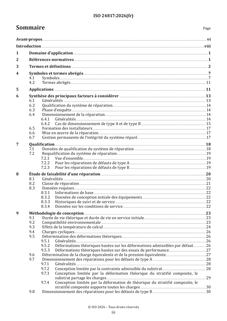
Sommaire Page
Avant-propos .vi
Introduction .viii
1 Domaine d'application . 1
2 Références normatives . 1
3 Termes et définitions . 2
4 Symboles et termes abrégés . 7
4.1 Symboles .7
4.2 Termes abrégés .11
5 Applications .11
6 Synthèse des principaux facteurs à considérer .13
6.1 Généralités . 13
6.2 Qualification du système de réparation .14
6.3 Phase d'enquête .14
6.4 Dimensionnement de la réparation .14
6.4.1 Généralités .14
6.4.2 Cas de dimensionnement de type A et de type B . 15
6.5 Formation des installateurs .17
6.6 Mise en œuvre de la réparation .17
6.7 Gestion permanente de l'intégrité du système réparé .17
7 Qualification .18
7.1 Données de qualification du système de réparation .18
7.2 Requalification du système de réparation .19
7.2.1 Vue d'ensemble.19
7.2.2 Pour les réparations de défauts de type A .19
7.2.3 Pour les réparations de défauts de type B .19
8 Étude de faisabilité d'une réparation .20
8.1 Généralités . 20
8.2 Classe de réparation .21
8.3 Données requises . 22
8.3.1 Informations de base . 22
8.3.2 Données de conception initiale des équipements . 22
8.3.3 Historiques de suivi et de service . 22
8.3.4 Données sur les conditions de service . 22
9 Méthodologie de conception.23
9.1 Durée de vie théorique et durée de vie en service initiale . 23
9.2 Compatibilité environnementale . 23
9.3 Effets de la température de calcul .24
9.4 Charges cycliques . 26
9.5 Détermination des déformations théoriques . 26
9.5.1 Généralités . 26
9.5.2 Déformations théoriques basées sur les déformations admissibles par défaut . 26
9.5.3 Déformations théoriques basées sur des essais de performance.27
9.6 Détermination de la charge équivalente et de la pression équivalente .27
9.7 Dimensionnement des réparations pour les défauts de type A . 28
9.7.1 Généralités . 28
9.7.2 Conception limitée par la contrainte admissible du substrat . 28
9.7.3 Conception limitée par la déformation théorique du stratifié composite, le
substrat partage les charges . . 29
9.7.4 Conception limitée par la déformation de théorique du stratifié composite, le
stratifié composite supporte toutes les charges . 30
9.8 Dimensionnement des réparations pour les défauts de type B . 30
iii
9.8.1 Généralités . 30
9.8.2 Détermination du facteur de service, f .31
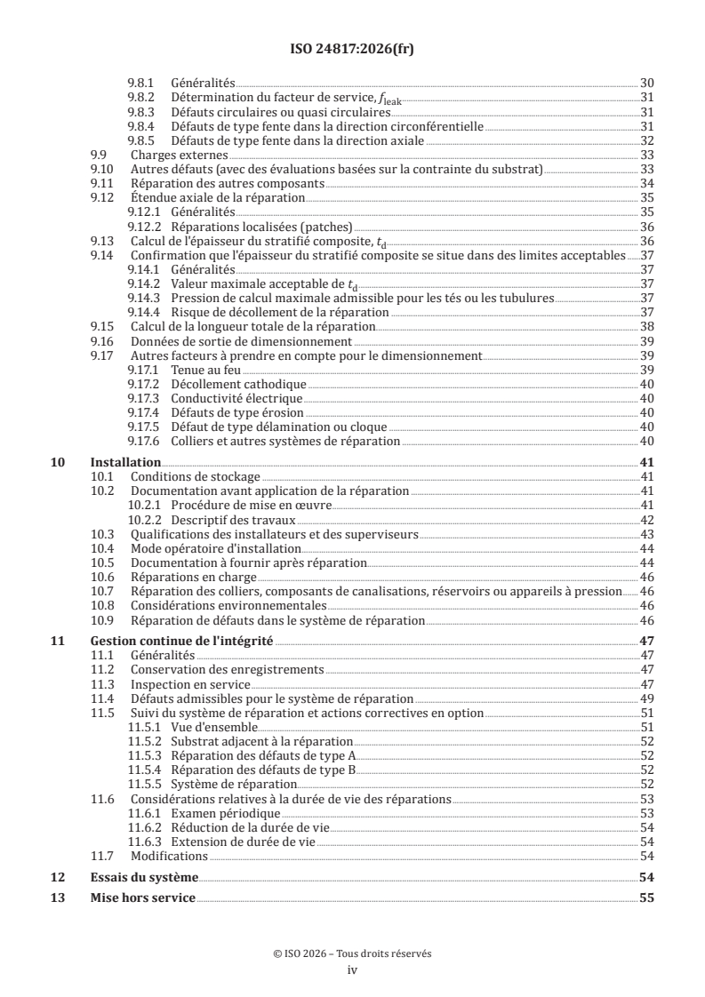
leak
9.8.3 Défauts circulaires ou quasi circulaires .31
9.8.4 Défauts de type fente dans la direction circonférentielle .31
9.8.5 Défauts de type fente dans la direction axiale .32
9.9 Charges externes . 33
9.10 Autres défauts (avec des évaluations basées sur la contrainte du substrat) . 33
9.11 Réparation des autres composants . 34
9.12 Étendue axiale de la réparation . 35
9.12.1 Généralités . 35
9.12.2 Réparations localisées (patches) . 36
9.13 Calcul de l'épaisseur du stratifié composite, t . 36
d
9.14 Confirmation que l'épaisseur du stratifié composite se situe dans des limites acceptables .37
9.14.1 Généralités .37
9.14.2 Valeur maximale acceptable de t .37
d
9.14.3 Pression de calcul maximale admissible pour les tés ou les tubulures .37
9.14.4 Risque de décollement de la réparation .37
9.15 Calcul de la longueur totale de la réparation. 38
9.16 Données de sortie de dimensionnement . 39
9.17 Autres facteurs à prendre en compte pour le dimensionnement . 39
9.17.1 Tenue au feu . 39
9.17.2 Décollement cathodique . 40
9.17.3 Conductivité électrique . 40
9.17.4 Défauts de type érosion . 40
9.17.5 Défaut de type délamination ou cloque . 40
9.17.6 Colliers et autres systèmes de réparation . 40
10 Installation . 41
10.1 Conditions de stockage .41
10.2 Documentation avant application de la réparation .41
10.2.1 Procédure de mise en œuvre . .41
10.2.2 Descriptif des travaux .42
10.3 Qualifications des installateurs et des superviseurs .43
10.4 Mode opératoire d'installation. 44
10.5 Documentation à fournir après réparation. 44
10.6 Réparations en charge . 46
10.7 Réparation des colliers, composants de canalisations, réservoirs ou appareils à pression . 46
10.8 Considérations environnementales . 46
10.9 Réparation de défauts dans le système de réparation . 46
11 Gestion continue de l'intégrité . 47
11.1 Généralités .47
11.2 Conservation des enregistrements .47
11.3 Inspection en service .47
11.4 Défauts admissibles pour le système de réparation . 49
11.5 Suivi du système de réparation et actions correctives en option .51
11.5.1 Vue d'ensemble.51
11.5.2 Substrat adjacent à la réparation .52
11.5.3 Réparation des défauts de type A .52
11.5.4 Réparation des défauts de type B .52
11.5.5 Système de réparation.52
11.6 Considérations relatives à la durée de vie des réparations . 53
11.6.1 Examen périodique . 53
11.6.2 Réduction de la durée de vie . 54
11.6.3 Extension de durée de vie . 54
11.7 Modifications . 54
12 Essais du système .54
13 Mise hors service .55
iv
Annexe A (informative) Design data sheet .56
Annexe B (normative) Données de qualification .59
Annexe C (normative) Essai de survie à court terme d'un tronçon de tube .64
Annexe D (normative) Mesurage de γ pour le calcul des défauts traversants .66
LCL
Annexe E (normative) Mesurage des données d'essais de performances .71
Annexe F (normative) Mesurage de la résilience (tenue à l'impact) . 74
Annexe G (normative) Mesurage du facteur de dégradation .75
Annexe H (normative) Qualification des systèmes de réparation pour les autres défauts (avec
des évaluations basées sur la contrainte du substrat) .77
Annexe I (informative) Guidance on the selection of the appropriate defect size and geometry
for through-wall defects (Type B defect) .80
Annexe J (normative) Qualification des installateurs .93
Annexe K (normative) Exigences et recommandations d'installation .96
Annexe L (informative) Design considerations .99
Annexe M (informative) Management of the integrity of composite repair systems to piping
and vessels .106
Bibliographie .110
v
Avant-propos
L'ISO (Organisation internationale de normalisation) est une fédération mondiale d'organismes nationaux
de normalisation (comités membres de l'ISO). L'élaboration des Normes internationales est en général
confiée aux comités techniques de l'ISO. Chaque comité membre intéressé par une étude a le droit de faire
partie du comité technique créé à cet effet. Les organisations internationales, gouvernementales et non
gouvernementales, en liaison avec l'ISO participent également aux travaux. L'ISO collabore étroitement avec
la Commission électrotechnique internationale (IEC) en ce qui concerne la normalisation électrotechnique.
Les procédures utilisées pour élaborer le présent document et celles destinées à sa mise à jour sont
décrites dans les Directives ISO/IEC, Partie 1. Il convient, en particulier, de prendre note des différents
critères d'approbation requis pour les différents types de documents ISO. Le présent document
a été rédigé conformément aux règles de rédaction données dans les Directives ISO/IEC, Partie 2
(voir www.iso.org/directives).
L'ISO attire l'attention sur le fait que la mise en application du présent document peut entraîner l'utilisation
d'un ou de plusieurs brevets. L'ISO ne prend pas position quant à la preuve, à la validité et à l'applicabilité de
tout droit de propriété revendiqué à cet égard. À la date de publication du présent document, l'ISO n'avait pas
reçu notification qu'un ou plusieurs brevets pouvaient être nécessaires à sa mise en application. Toutefois,
il y a lieu d'avertir les responsables de la mise en application du présent document que des informations
plus récentes sont susceptibles de figurer dans la base de données de brevets, disponible à l'adresse
www.iso.org/brevets. L'ISO ne saurait être tenue pour responsable de ne pas avoir identifié tout ou partie de
tels droits de brevet.
Les appellations commerciales éventuellement mentionnées dans le présent document sont données pour
information, par souci de commodité, à l'intention des utilisateurs et ne sauraient constituer un engagement.
Pour une explication de la nature volontaire des normes, la signification des termes et expressions
spécifiques de l'ISO liés à l'évaluation de la conformité, ou pour toute information au sujet de l'adhésion de
l'ISO aux principes de l'Organisation mondiale du commerce (OMC) concernant les obstacles techniques au
commerce (OTC), voir www.iso.org/avant-propos.
Le présent document a été élaboré par le comité technique ISO/TC 67, Industries du pétrole et du gaz,
y compris les énergies à faible teneur en carbone, sous-comité SC 6, Équipements des procédés, tuyauteries,
systèmes, et sécurité qui y est rattachée, en collaboration avec le comité technique CEN/TC 12, Industries du
pétrole et du gaz, y compris les énergies à faible teneur en carbone, du Comité européen de normalisation
(CEN), conformément à l'Accord de coopération technique entre l'ISO et le CEN (Accord de Vienne).
Cette troisième édition annule et remplace la deuxième édition (ISO 24817:2017), qui a fait l'objet d'une
révision technique.
Les principales modifications sont les suivantes:
— l'Article 7 a été divisé en trois Articles distincts, 7 Qualification, 8 Étude de faisabilité d'une réparation
et 9 Méthodologie de conception pour permettre un référencement clair;
— dans «9 Méthodologie de conception», les différentes phases de conception ont été réorganisées de
sorte qu'elles soient désormais présentées dans la séquence de leur utilisation pour faciliter le suivi et le
passage en revue;
— lorsque plusieurs options de conception sont présentées, des éléments de clarification ont été ajoutés
pour indiquer à quel moment il convient de sélectionner chacune d'elles;
— des durées de vie théoriques allant jusqu'à 50 ans peuvent désormais être envisagées. Les recommandations
fournies concernant leur gestion en service pour cette période prolongée ont été renforcées;
— les exigences relatives à la prise en compte des effets de la température ont été clarifiées;
— l'évaluation de la charge cyclique a été mise à jour pour maintenir son équivalence avec les
recommandations de l'ISO 14692;
vi
— les effets de Poisson ont été passés en revue et mis à jour;
— les formules de conception de type A ont été ré-organisées de sorte qu'elles puissent toutes être calculées
plutôt qu'avec certaines nécessitant une itération;
— les considérations relatives à mise en œuvre de réparations sur des conduites en service (sous pression)
ont été révisées;
— des recommandations sur l'utilisation de matériaux composites pour renforcer les défauts tels que les
défauts de type fissures ont été ajoutées;
— la méthode d'essai pour déterminer la valeur de déformation théorique spécifiée à l'Annexe E a été
révisée afin d'éliminer l'influence du substrat dans les essais;
— les unités des variables ont été normalisées dans l'ensemble du document. La modification principale
concerne la valeur du taux moyen de libération d'énergie, γ , qui est désormais en N mm, non plus en
LCL
−2
J m ;
— ajout d'une nouvelle Annexe I pour fournir des recommandations sur la manière d'évaluer les exigences
relatives à la mise en œuvre des réparations aux défauts de type B.
Il convient que l'utilisateur adresse tout retour d'information ou toute question concernant le présent
document à l'organisme national de normalisation de son pays. Une liste exhaustive desdits organismes se
trouve à l'adresse www.iso.org/fr/members.html.
vii
Introduction
L'objectif du présent document est de s'assurer que les canalisations, conduites de transport, réservoirs et
appareils à pression réparés en utilisant des systèmes composites qui sont qualifiés, conçus, installés et
contrôlés en utilisant le présent document satisfont aux exigences de performance spécifiées. Les principaux
utilisateurs du présent document sont les propriétaires/exploitants d'installations et d'équipements, les
maîtres d'œuvre chargés de la conception, de l'installation, de la maintenance et de l'inspection, les sous-
traitants chargés de la fourniture du système de réparation, et les organismes de contrôle.
viii
Norme internationale ISO 24817:2026(fr)
Industries du petrole et du gaz, y compris les énergies à faible
teneur en carbone — Reparations en materiau composite
pour tuyauterie — Conformite aux exigences de performance
et conception, installation, essai et gestion de l’intégrité
1 Domaine d'application
Le présent document spécifie les exigences et donne les recommandations relatives à la qualification, à la
conception, à l'installation, aux essais et à la gestion de l'intégrité lors de l'application externe de systèmes
de réparation composites à des canalisations, conduites de transport, réservoirs et appareils à pression
corrodés ou endommagés.
2 Références normatives
Les documents suivants sont cités dans le texte de sorte qu'ils constituent, pour tout ou partie de leur
contenu, des exigences du présent document. Pour les références datées, seule l'édition citée s'applique. Pour
les références non datées, la dernière édition du document de référence s'applique (y compris les éventuels
amendements).
ISO 75-3, Plastiques — Détermination de la température de fléchissement sous charge — Partie 3: Stratifiés
thermodurcissables à haute résistance et plastiques renforcés de fibres longues
ISO 527-1, Plastiques — Détermination des propriétés en traction — Partie 1: Principes généraux
ISO 527-2, Plastiques — Détermination des propriétés en traction — Partie 2: Conditions d'essai des plastiques
pour moulage et extrusion
ISO 527-4, Plastiques — Détermination des propriétés en traction — Partie 4: Conditions d'essai pour les
composites plastiques renforcés de fibres isotropes et orthotropes
ISO 8501 (toutes les parties), Préparation des subjectiles d’acier avant application de peintures et de produits
assimilés — Évaluation visuelle de la propreté d’un subjectile
ISO 868, Plastiques et ébonite — Détermination de la dureté par pénétration au moyen d'un duromètre (dureté
Shore)
ISO 10952, Tubes et raccords en plastiques thermodurcissables renforcés de verre (PRV) — Détermination de la
résistance à une attaque chimique à l'intérieur d'un tronçon de tube soumis à déflexion
ISO 11357-2, Plastiques — Analyse calorimétrique différentielle (DSC) — Partie 2: Détermination de la
température et de la hauteur de palier de transition vitreuse
ISO 11359-2, Plastiques — Analyse thermomécanique (TMA) — Partie 2: Détermination du coefficient de
dilatation thermique linéique et de la température de transition vitreuse
ISO 14692, Industries du pétrole et du gaz naturel — Canalisations en plastique renforcé de verre (PRV)
ASTM C581, Standard Practice for Determining Chemical Resistance of Thermosetting Resins Used in Glass-
Reinforced Structures Intended for Liquid Service
ASTM D543, Standard Practices for Evaluating the Resistance of Plastics to Chemical Reagents
ASTM D638, Standard Test Method for Tensile Properties of Plastics
ASTM D696, Standard Test Method for Coefficient of Linear Thermal Expansion of Plastics Between Minus 30 °C
and 30 °C with a Vitreous Silica Dilatometer
ASTM D1598, Standard Test Method for Time-to-Failure of Plastic Pipe under Constant Internal Pressure
ASTM D1599, Standard Test Method for Resistance to Short-Time Hydraulic Pressure of Plastic Pipe, Tubing, and
Fittings
ASTM D2583, Standard Test Method for Indentation Hardness of Rigid Plastics by Means of a Barcol Impressor
ASTM D2992, Standard Practice for Obtaining Hydrostatic or Pressure Design Basis for Fiberglass (Glass-Fiber-
Reinforced Thermosetting-Resin) Pipe and Fittings
ASTM D3039, Standard Test Method for Tensile Properties of Polymer Matrix Composite Materials
ASTM D3165, Standard Test Method for Strength Properties of Adhesives in Shear by Tension Loading of Single-
Lap-Joint Laminated Assemblies
ASTM D3681, Standard Test Method for Chemical Resistance of Fiberglass (Glass-Fiber-Reinforced Thermosetting
Resin) Pipe in a Deflected Condition
ASTM D5379, Standard Test Method for Shear Properties of Composite Materials by the V-Notched Beam Method
ASTM D6604, Standard Practice for Glass Transition Temperatures of Hydrocarbon Resins by Differential
Scanning Calorimetry
ASTM E831, Standard Test Method for Linear Thermal Expansion of Solid Materials by Thermomechanical
Analysis
ASTM E1640, Standard Test Method for Assignment of the Glass Transition Temperature by Dynamic Mechanical
Analysis
ASTM E2092, Standard Test Method for Distortion Temperature in Three-Point Bending by Thermomechanical
Analysis
ASTM G8, Standard Test Methods for Cathodic Disbonding of Pipeline Coatings
EN 59, Matières plastiques renforcées de verre — Détermination de la dureté par pénétration au moyen d’un
appareil d’essai de dureté Barcol (BS 2782-10, Méthode 1001, Détermination de la dureté par pénétration au
moyen d’un appareil d’essai de dureté Barcol)
EN 1465, Adhésifs — Détermination de la résistance au cisaillement en traction d’assemblages collés à
recouvrement simple
3 Termes et définitions
Pour les besoins du présent document, les termes et définitions suivants s'appliquent.
L'ISO et l'IEC tiennent à jour des bases de données terminologiques destinées à être utilisées en normalisation,
consultables aux adresses suivantes:
— ISO Online browsing platform: disponible à l'adresse https:// www .iso .org/ obp
— IEC Electropedia: disponible à l'adresse https:// www .electropedia .org/
3.1
dureté Barcol
mesurage de la dureté superficielle à l'aide d'une machine d'indentation en surface
3.2
cloque
vide d'air entre les couches (3.23) d'un composite (3.4), apparaissant en surface sous la forme d'une zone
surélevée
3.3
composite
système de résine thermodurcissable (3.49) renforcé par des fibres
3.4
stratifié composite
composite
composite de réparation
partie d'un système de réparation (3.39) constituée du composite (3.3)
Note 1 à l'article: La plupart des composites examinés dans le présent document sont constitués de feuilles ou de
couches (3.23) distinctes enroulées ou empilées les unes sur les autres. Cette construction empilée forme un stratifié.
3.5
fissure
fissure dans le stratifié composite (3.4) s'étendant perpendiculairement à la surface, de telle sorte qu'il y a
une séparation réelle avec les surfaces opposées
3.6
polymérisation
solidification d'un système de résine thermodurcissable (3.49) (polyester ou époxy) par une réaction chimique
irréversible
3.7
vitesse de polymérisation
profil temps-température qualifié pour générer une température de transition vitreuse (3.17), T ou une
g
température de fléchissement sous charge (HDT) (3.19) spécifiée
3.8
délamination
zone de séparation entre les couches (3.23) du stratifié composite (3.4)
3.9
durée de vie théorique
période de temps utilisée dans les calculs de conception qui est en général la période maximale pendant
laquelle la réparation est censée être nécessaire
Note 1 à l'article: La durée de vie théorique ne doit pas être interprétée comme la durée de vie en service (3.44)
réalisable du système réparé.
3.10
température de calcul
température maximale pour laquelle la réparation est conçue (la température la plus élevée à laquelle le
composant à réparer est supposé être exposé en service)
3.11
analyse calorimétrique différentielle
DSC
méthode permettant de déterminer la température de transition vitreuse (3.17) d'une résine
thermodurcissable
3.12
décollement
délamination d'interface
surface entre le stratifié composite (3.4) et le substrat (3.46) qu'il convient de coller, mais au niveau de
laquelle aucune liaison n'existe
3.13
fibre exposée
zone de fibre non imprégnée de résine qui dépasse du corps de la réparation
3.14
matériau de remplissage
matière utilisée pour réparer les imperfections superficielles externes avant l'application du stratifié
composite (3.4)
3.15
corps étranger
toute substance autre que la fibre de renfort ou d'autres matériaux qui forment une partie du système de
réparation (3.39)
3.16
matériaux de finition
couche finale de matériau pour aider à compacter le stratifié composite (3.4) (un film polymère ou un tissu,
en général)
Note 1 à l'article: Il convient de les ôter entièrement après la polymérisation de la réparation et avant le contrôle de
dureté ou la mise en peinture de la réparation.
3.17
température de transition vitreuse
température à laquelle les propriétés physiques d'une résine changent de manière sensible
3.18
durcisseur
composant ajouté à une résine thermodurcissable afin de provoquer sa polymérisation (3.6)
3.19
température de fléchissement sous charge
HDT
température à laquelle une éprouvette d'essai se déforme d'une ampleur spécifiée sous une charge prescrite
3.20
organisme de contrôle
entité chargée de vérifier que la réparation est conforme aux exigences
3.21
installateur
personne qualifiée pour mettre en œuvre un système de réparation (3.39) composite
3.22
température d'installation
température prévue de la surface du substrat (3.46) (composant) au moment de la mise en œuvre de la
réparation
3.23
couche
feuille individuelle ou enroulement à l'intérieur du stratifié composite (3.4)
3.24
fuite
perforation du substrat (3.46) avec perte de confinement
3.25
groupe de matériaux
famille de substrats
classe d'alliages métallurgiques ou de matériaux dont les éléments ont des compositions chimiques similaires
EXEMPLE Les fontes, les aciers au carbone, les aciers inoxydables austénitiques, les résines époxy renforcées de
verre (GRE), les esters vinyliques renforcés de verre (GRVE) et les polyesters insaturés renforcés de verre (GRuP)
3.26
durée de vie en service initiale maximale
minimum de la durée de vie théorique (3.9) ou 20 ans
Note 1 à l'article: Voir le Tableau 5
3.27
durée de vie théorique maximale
valeur maximale qui peut être sélectionnée pour la durée de vie théorique (3.9)
Note 1 à l'article: Voir le Tableau 5
3.28
charge occasionnelle
charge qui se produit rarement et sur une courte durée
Note 1 à l'article: Les charges occasionnelles apparaissent généralement moins de 10 fois au cours de la durée de vie du
composant et leur durée respective est inférieure à 30 min.
3.29
température de service
température à laquelle la réparation est supposée fonctionner
3.30
propriétaire/exploitant
organisation qui possède ou exploite le composant à réparer
3.31
piqûre
trou d'épingle dans la couche de résine superficielle externe, ne se prolongeant pas dans le composite (3.4)
3.32
conduite de transport
tuyau dont les composants sont soumis aux mêmes conditions de conception que celles utilisées pour
transporter les fluides entre les installations
Note 1 à l'article: Les composants incluent par exemple les raccords, les brides et les vannes.
3.33
canalisation
système de canalisations
tuyauterie
ensembles de composants utilisés pour acheminer les fluides dans une installation
Note 1 à l'article: Les composants comprennent le tuyau, les raccords, les brides et les vannes. Un système de
canalisations est souvent au-dessus du sol, mais peut parfois être enterré.
3.34
creux
sous-épaisseur localisée en surface du stratifié composite (3.4)
3.35
traitement de polymérisation (ou post-cuisson)
traitement (3.6) additionnel à température élevée, appliqué après la polymérisation de la résine afin de
s'assurer que la température de transition vitreuse (3.17) requise est atteinte
3.36
mode opératoire d'application pour la qualification
mode opératoire destiné à réaliser les essais de qualification et utilisé ensuite pour installer les réparations
3.37
température d'essai de qualification
température à laquelle sont réalisés les essais de qualification du système de réparation (3.39)
3.38
renfort
fibre incorporée dans le système de résine (3.42)
Note 1 à l'article: Les matières de fibre possibles sont l'aramide, le carbone, le verre, les polyesters ou des matériaux
similaires. Le renfort accroît les propriétés mécaniques par rapport à la résine de base.
3.39
système de réparation
système composé du substrat (3.46), stratifié composite (3.4), du matériau de remplissage (3.14), de l'adhésif
et incluant les méthodes d'installation et de préparation des surfaces
3.40
installateur du système de réparation
société qui installe le système de réparation (3.39)
3.41
fournisseur du système de réparation
société qui conçoit et fournit le système de réparation (3.39)
3.42
système de résine
tous les composants formant la matrice d'un composite (3.3)
Note 1 à l'article: Ce terme désigne souvent une résine, un (des) matériau(x) de remplissage, un pigment, des
modificateurs de propriétés mécaniques, et un catalyseur ou un durcisseur (3.18).
3.43
risque
événement englobant ce qui peut se produire (scénario), sa vraisemblance (probabilité) et son niveau ou
degré de dommage (conséquences)
3.44
durée de vie en service
durée de vie définie
durée pendant laquelle il est prévu que le propriétaire/exploitant (3.30) maintienne la réparation en service
Note 1 à l'article: Cette durée ne doit pas dépasser la durée de vie théorique (3.9). Une stratégie de maintenance
appropriée doit être spécifiée et mise en œuvre pour atteindre la durée de vie en service requise, voir 11.5.
3.45
bouche-trou
solutions temporaires appliquées pour arrêter les fuites (3.24) en cours et permettre ainsi la mise en place
d'une réparation en matériau composite (3.3)
Note 1 à l'article: Les bouche-trous ne rétablissent pas l'intégrité du composant et ont une durée de vie prévue de
l'ordre de quelques jours à quelques semaines.
3.46
substrat
surface à laquelle une réparation est appliquée
3.47
superviseur
installateur (3.21) expérimenté qui est qualifié après avoir suivi avec succès le stage de formation
correspondant
3.48
dureté Shore
mesurage de la dureté superficielle à l'aide d'une machine d'indentation en surface ou d'un duromètre
3.49
système de résine thermodurcissable
système de résine (3.42) qui ne peut pas être fondu ou remoulé après la polymérisation
3.50
défaut de type A
défaut apparaissant à l'intérieur du substrat (3.46) lorsque l'épaisseur de paroi subsistant à la fin de la durée
de vie théorique (3.9) es
...