

ISO/FDIS 25408-1
(Main)Testing method for bead wire — Part 1: General requirements
- Abstract
This document specifies test methods of round steel Bead Wires which are used for tyre reinforcement.Test methods on Mechanical properties and Chemical properties (coating analysis) are included. By agreement, these test methods may be applied to similar single filaments used for reinforcing other rubber products.
- Status
- Not Published
- Technical Committee
- ISO/TC 17/SC 17 - Steel wire rod and wire products
- Drafting Committee
- ISO/TC 17/SC 17 - Steel wire rod and wire products
- Current Stage
- 5020 - FDIS ballot initiated: 2 months. Proof sent to secretariat
- Start Date
- 26-Aug-2026
- Completion Date
- 26-Aug-2026
Buy Documents
ISO/FDIS 25408-1 - Testing method for bead wire — Part 1: General requirements

REDLINE ISO/FDIS 25408-1 - Testing method for bead wire — Part 1: General requirements
ISO/FDIS 25408-1 is an ISO document for testing round steel bead wires (BW) used in tyre reinforcement. It specifies methods for checking geometry, mechanical properties and bronze coating composition, and by agreement it can also be applied to similar single filaments used to reinforce other rubber products.
What does ISO/FDIS 25408-1 specify?
ISO/FDIS 25408-1 specifies a common set of test methods for bead wire and the way those tests are organized and reported. The document is arranged as a practical laboratory method: scope, references, terms, then separate clauses for diameter, tensile performance, bend, torsion, residual torsion, straightness, tip rise and S-shape, and XRFS coating analysis.
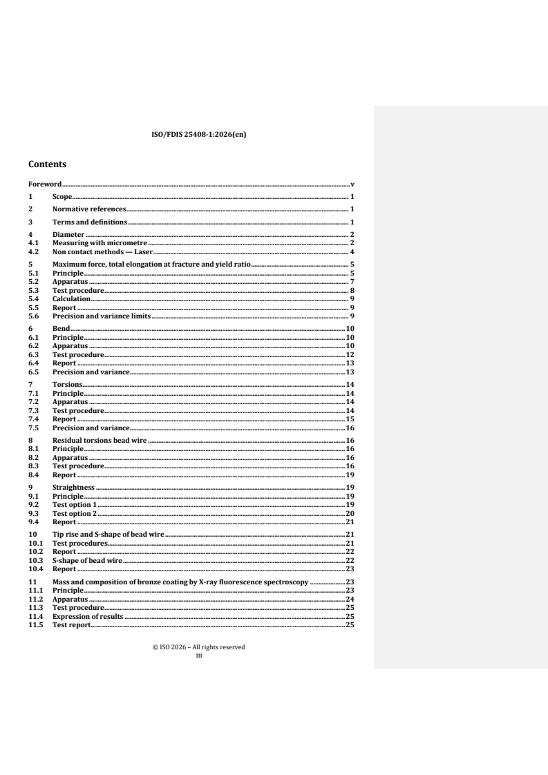
| Clause | What it covers |
|---|---|
| 1 | Scope |
| 2 | Normative references |
| 3 | Terms and definitions |
| 4 | Diameter |
| 5 | Maximum force, total elongation at fracture and yield ratio |
| 6 | Bend |
| 7 | Torsions |
| 8 | Residual torsions bead wire |
| 9 | Straightness |
| 10 | Tip rise and S-shape of bead wire |
| 11 | Mass and composition of bronze coating by X-ray fluorescence spectroscopy |
The scope is focused on round steel bead wires for tyre reinforcement, with test methods for mechanical properties and coating analysis. Clause 11 extends the technical coverage from shape and strength to bronze coating mass and composition, which matters when the wire surface condition affects performance or supplier acceptance.
What are the key requirements of ISO/FDIS 25408-1?
Diameter and roundness
Clause 4 gives two ways to measure diameter: with a micrometre or with non-contact laser methods. In practice, this means a lab can choose contact or optical measurement, but it must still take multiple readings and calculate average diameter and out-of-roundness in a controlled way.
For micrometre measurements, the specimen must be clean, as straight as possible, and measured with a precision micrometre with 0.001 mm resolution. For laser methods, the sample must be clean, perpendicular to the beam, and measurable at multiple angles so the average diameter and roundness can be determined. This matters because diameter and ovality affect how the wire fits and behaves in tyre reinforcement.
Tensile properties
Clause 5 sets out the tensile test for maximum force, total elongation at fracture and yield ratio. It uses a constant rate of extension tensile testing machine, suitable grips, and optionally an extensometer, with test settings for preload, test speed and gauge length.
The procedure also allows thermal aging when requested, with standard aging conditions given in the clause. The test is run at room temperature unless otherwise specified, and invalid results are rejected when fracture occurs in or close to the grips. For users, this means the lab has to control clamping, speed, temperature and reporting so the force-elongation curve is meaningful and comparable between suppliers.
Clause 5 also gives software functions needed for the calculation of the reported values, and Table 1 gives acceptable coefficient of variation (CV) limits for force, elongation and yield ratio by bead wire diameter. When those CV limits are exceeded, measurement system analysis (MSA) is required, so the result is not accepted at face value without checking the test system.
Bend and torsion behavior
Clause 6 covers the reverse bend test. The specimen is bent alternately left and right around a defined device until fracture, and the number of reverse bends is reported. Table 2 gives the bend device parameters by wire diameter, and Table 3 gives acceptable CV limits for the result. In practice, this test shows how the wire tolerates repeated plastic deformation before breaking.
Clause 7 covers the simple torsion test. One end of the wire is fixed and the other is rotated until fracture or a specified number of turns is reached. The clause specifies sample preparation, test speed, axial load and grip conditions, and it invalidates tests where torsion occurs in the clamp area. This matters because torsion resistance is a key indicator of handling and service behavior in wire products.
Residual torsions, straightness and shape
Clause 8 measures residual torsions on a 6 m length of bead wire taken from a spool. The wire is bent and then released so the end rotations can be counted, and the result is reported to the nearest 0.25 turns per 6 m. This helps users judge whether the wire carries unwanted twist from production or winding.
Clause 9 gives two straightness options: a 3 m parallel-line check or an arc-height method. The first gives a practical OK/NO OK result, while the second provides a measured height in millimetres. Clause 10 adds visual checks for tip rise and S-shape during the residual torsion check. C-shape is acceptable, while S-shape is not, so the document links visual form directly to product acceptance.
Bronze coating analysis
Clause 11 uses X-ray fluorescence spectroscopy (XRFS) to determine coating mass and composition. The sample has to be prepared in a defined way, the instrument must be calibrated with suitable standards, and the results are calculated from the measured copper and tin signals. The report gives tin mass fraction and coating mass with stated rounding. For buyers and producers, this is the clause that connects surface chemistry to specification control.
What terms does ISO/FDIS 25408-1 define?
- Diameter - the average of the maximum and minimum values measured on the same section of the specimen.
- Out-of-roundness - the absolute difference between the maximum and minimum diameter measured across one transverse cross-section.
- Maximum force (Fm) - the highest load the material withstands in the static tensile test, expressed in newtons.
- Total elongation at fracture - the percentage increase in length at the point of fracture compared with the original gauge length.
- Yield strength - the highest stress a material can take before plastic deformation begins.
- Yield ratio - the force ratio at 0.2 % elongation offset to maximum force, expressed as a percentage.
- Tensile strength (Rm) - the maximum force divided by the original cross-sectional area.
- Straightness - the maximum bow height, or curvature, measured over a given gauge length of wire.
Who uses ISO/FDIS 25408-1?
ISO/FDIS 25408-1 is used in the tyre-reinforcement supply chain, especially where round steel bead wire must be checked consistently before use. Bead wire manufacturers, tyre makers, testing laboratories, quality managers and purchasing teams use it for incoming inspection, product release, supplier comparison and dispute resolution.
It is also relevant when a buyer and supplier agree to apply the methods to similar single filaments for other rubber products. In practice, that makes the document useful wherever wire geometry, tensile performance, torsion behavior or coating composition must be measured in the same way by different organizations.
Which standards are used with ISO/FDIS 25408-1?
- ISO 7800:2012 - referenced for simple torsion testing, and Clause 7 points to Annex B of that standard for fracture evaluation when needed.
- ISO 16650:2025 - the bead wire standard referenced for terminology and for the definition of total elongation at fracture used in Clause 3.
Related standards listed in the bibliography are:
- ISO 6892-1:2019 - room-temperature tensile testing for metallic materials.
- ISO 7801:2024 - reverse bend testing for metallic materials.
What does the ISO/FDIS 25408-1 document contain?
ISO/FDIS 25408-1 contains the test principles, apparatus descriptions, specimen preparation steps, operating conditions, calculations and reporting rules for each method. It also includes tables for acceptance limits, bend-device parameters and XRFS calibration standards, plus figures that show the test setups and evaluation methods.
The document gives worked procedures for micrometre and laser diameter measurement, tensile testing, reverse bending, torsion, residual torsion, straightness, tip rise and S-shape inspection, and bronze coating analysis. It also states precision or variance limits for several results, which helps laboratories judge whether their measurement process is stable enough for routine use.
Buy Documents
ISO/FDIS 25408-1 - Testing method for bead wire — Part 1: General requirements
REDLINE ISO/FDIS 25408-1 - Testing method for bead wire — Part 1: General requirements
Get Certified
Connect with accredited certification bodies for this standard

DIN CERTCO
DIN Group product certification.

Element Materials Technology
Materials testing and product certification.
Inštitut za kovinske materiale in tehnologije
Institute of Metals and Technology. Materials testing, metallurgical analysis, NDT.
Sponsored listings
Frequently Asked Questions
ISO/FDIS 25408-1 is a draft published by the International Organization for Standardization (ISO). Its full title is "Testing method for bead wire — Part 1: General requirements". This standard covers: This document specifies test methods of round steel Bead Wires which are used for tyre reinforcement.Test methods on Mechanical properties and Chemical properties (coating analysis) are included. By agreement, these test methods may be applied to similar single filaments used for reinforcing other rubber products.
This document specifies test methods of round steel Bead Wires which are used for tyre reinforcement.Test methods on Mechanical properties and Chemical properties (coating analysis) are included. By agreement, these test methods may be applied to similar single filaments used for reinforcing other rubber products.
ISO/FDIS 25408-1 is classified under the following ICS (International Classification for Standards) categories: 77.140.65 - Steel wire, wire ropes and link chains; 83.140.01 - Rubber and plastics products in general; 83.160.01 - Tyres in general. The ICS classification helps identify the subject area and facilitates finding related standards.
ISO/FDIS 25408-1 is available in PDF format for immediate download after purchase. The document can be added to your cart and obtained through the secure checkout process. Digital delivery ensures instant access to the complete standard document.
Standards Content (Sample)
FINAL DRAFT
International
Standard
ISO/TC 17/SC 17
Testing method for bead wire —
Secretariat: SAC
Part 1:
Voting begins on:
2026-08-26
General requirements
Voting terminates on:
Méthode d'essai pour les fils de tringle —
2026-10-21
Partie 1: Exigences générales
RECIPIENTS OF THIS DRAFT ARE INVITED TO SUBMIT,
WITH THEIR COMMENTS, NOTIFICATION OF ANY
RELEVANT PATENT RIGHTS OF WHICH THEY ARE AWARE
AND TO PROVIDE SUPPOR TING DOCUMENTATION.
IN ADDITION TO THEIR EVALUATION AS
BEING ACCEPTABLE FOR INDUSTRIAL, TECHNO-
LOGICAL, COMMERCIAL AND USER PURPOSES, DRAFT
INTERNATIONAL STANDARDS MAY ON OCCASION HAVE
TO BE CONSIDERED IN THE LIGHT OF THEIR POTENTIAL
TO BECOME STAN DARDS TO WHICH REFERENCE MAY BE
MADE IN NATIONAL REGULATIONS.
Reference number
FINAL DRAFT
International
Standard
ISO/TC 17/SC 17
Testing method for bead wire —
Secretariat: SAC
Part 1:
Voting begins on:
General requirements
Voting terminates on:
Méthode d'essai pour les fils de tringle —
Partie 1: Exigences générales
RECIPIENTS OF THIS DRAFT ARE INVITED TO SUBMIT,
WITH THEIR COMMENTS, NOTIFICATION OF ANY
RELEVANT PATENT RIGHTS OF WHICH THEY ARE AWARE
AND TO PROVIDE SUPPOR TING DOCUMENTATION.
© ISO 2026
IN ADDITION TO THEIR EVALUATION AS
All rights reserved. Unless otherwise specified, or required in the context of its implementation, no part of this publication may
BEING ACCEPTABLE FOR INDUSTRIAL, TECHNO-
LOGICAL, COMMERCIAL AND USER PURPOSES, DRAFT
be reproduced or utilized otherwise in any form or by any means, electronic or mechanical, including photocopying, or posting on
INTERNATIONAL STANDARDS MAY ON OCCASION HAVE
the internet or an intranet, without prior written permission. Permission can be requested from either ISO at the address below
TO BE CONSIDERED IN THE LIGHT OF THEIR POTENTIAL
or ISO’s member body in the country of the requester.
TO BECOME STAN DARDS TO WHICH REFERENCE MAY BE
MADE IN NATIONAL REGULATIONS.
ISO copyright office
CP 401 • Ch. de Blandonnet 8
CH-1214 Vernier, Geneva
Phone: +41 22 749 01 11
Email: copyright@iso.org
Website: www.iso.org
Published in Switzerland Reference number
ii
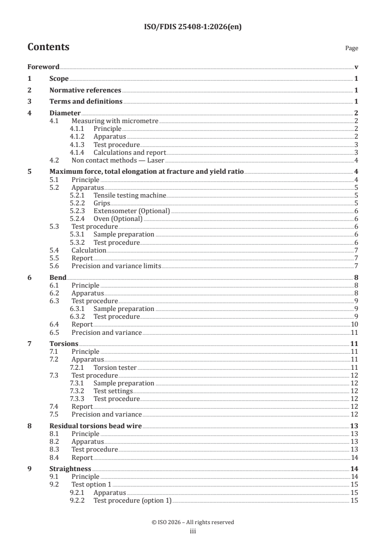
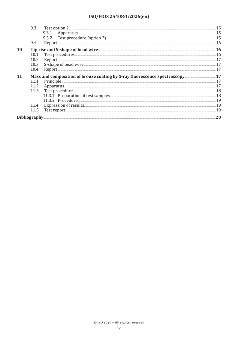
Contents Page
Foreword .v
1 Scope . 1
2 Normative references . 1
3 Terms and definitions . 1
4 Diameter . 2
4.1 Measuring with micrometre .2
4.1.1 Principle .2
4.1.2 Apparatus .2
4.1.3 Test procedure.3
4.1.4 Calculations and report .3
4.2 Non contact methods — Laser .4
5 Maximum force, total elongation at fracture and yield ratio . 4
5.1 Principle .4
5.2 Apparatus .5
5.2.1 Tensile testing machine .5
5.2.2 Grips.5
5.2.3 Extensometer (Optional) .6
5.2.4 Oven (Optional) .6
5.3 Test procedure .6
5.3.1 Sample preparation .6
5.3.2 Test procedure.6
5.4 Calculation .7
5.5 Report .7
5.6 Precision and variance limits .7
6 Bend . 8
6.1 Principle .8
6.2 Apparatus .8
6.3 Test procedure .9
6.3.1 Sample preparation .9
6.3.2 Test procedure.9
6.4 Report .10
6.5 Precision and variance .11
7 Torsions .11
7.1 Principle .11
7.2 Apparatus .11
7.2.1 Torsion tester .11
7.3 Test procedure . 12
7.3.1 Sample preparation . 12
7.3.2 Test settings. 12
7.3.3 Test procedure. 12
7.4 Report . 12
7.5 Precision and variance . 12
8 Residual torsions bead wire .13
8.1 Principle . 13
8.2 Apparatus . 13
8.3 Test procedure . 13
8.4 Report .14
9 Straightness . 14
9.1 Principle .14
9.2 Test option 1 . 15
9.2.1 Apparatus . 15
9.2.2 Test procedure (option 1) . 15
iii
9.3 Test option 2 . 15
9.3.1 Apparatus . 15
9.3.2 Test procedure (option 2) . 15
9.4 Report .16
10 Tip rise and S-shape of bead wire .16
10.1 Test procedures .16
10.2 Report .17
10.3 S-shape of bead wire .17
10.4 Report .17
11 Mass and composition of bronze coating by X-ray fluorescence spectroscopy . 17
11.1 Principle .17
11.2 Apparatus .17
11.3 Test procedure .18
11.3.1 Preparation of test samples .18
11.3.2 Procedure .19
11.4 Expression of results .19
11.5 Test report .19
Bibliography .20
iv
Foreword
ISO (the International Organization for Standardization) is a worldwide federation of national standards
bodies (ISO member bodies). The work of preparing International Standards is normally carried out through
ISO technical committees. Each member body interested in a subject for which a technical committee
has been established has the right to be represented on that committee. International organizations,
governmental and non-governmental, in liaison with ISO, also take part in the work. ISO collaborates closely
with the International Electrotechnical Commission (IEC) on all matters of electrotechnical standardization.
The procedures used to develop this document and those intended for its further maintenance are described
in the ISO/IEC Directives, Part 1. In particular, the different approval criteria needed for the different types
of ISO document should be noted. This document was drafted in accordance with the editorial rules of the
ISO/IEC Directives, Part 2 (see www.iso.org/directives).
ISO draws attention to the possibility that the implementation of this document may involve the use of (a)
patent(s). ISO takes no position concerning the evidence, validity or applicability of any claimed patent
rights in respect thereof. As of the date of publication of this document, ISO had not received notice of (a)
patent(s) which may be required to implement this document. However, implementers are cautioned that
this may not represent the latest information, which may be obtained from the patent database available at
www.iso.org/patents. ISO shall not be held responsible for identifying any or all such patent rights.
Any trade name used in this document is information given for the convenience of users and does not
constitute an endorsement.
For an explanation of the voluntary nature of standards, the meaning of ISO specific terms and expressions
related to conformity assessment, as well as information about ISO's adherence to the World Trade
Organization (WTO) principles in the Technical Barriers to Trade (TBT), see www.iso.org/iso/foreword.html.
This document was prepared by Technical Committee ISO/TC 17, Steel, Subcommittee SC 17, Steel wire rod
and wire products.
A list of all parts in the ISO 25408 series can be found on the ISO website.
Any feedback or questions on this document should be directed to the user’s national standards body. A
complete listing of these bodies can be found at www.iso.org/members.html.
v
FINAL DRAFT International Standard ISO/FDIS 25408-1:2026(en)
Testing method for bead wire —
Part 1:
General requirements
1 Scope
This document specifies test methods of round steel bead wires (BW) which are used for tyre reinforcement.
Test methods on mechanical properties and chemical properties (coating analysis) are included.
By agreement, these test methods can be applied to similar single filaments used for reinforcing other
rubber products.
2 Normative references
The following documents are referred to in the text in such a way that some or all of their content constitutes
requirements of this document. For dated references, only the edition cited applies. For undated references,
the latest edition of the referenced document (including any amendments) applies.
ISO 7800:2012, Metallic materials — Wire — Simple torsion test
3 Terms and definitions
For the purposes of this document, the following terms and definitions apply.
ISO and IEC maintain terminology databases for use in standardization at the following addresses:
— ISO Online browsing platform: available at https:// www .iso .org/ obp
— IEC Electropedia: available at https:// www .electropedia .org/
3.1
diameter
average of maximum and minimum values in multiple transversal measurements on the same section of the
specimen.
3.2
out-of-roundness
absolute value of the arithmetic difference between the maximum and minimum diameter measured in the
same transverse cross-section perpendicular to the wire axis
3.3
maximum force
F
m
highest load that the material withstands when subjected to the static tensile test is represented, expressed
in newtons
Note 1 to entry: Maximum force is not equal to breaking load.
3.4
total elongation at fracture
percentage of the ratio of the arithmetic value of subtracting the original gauge length from the total length
of the specimen at the time of fracture to the original gauge length
[SOURCE: ISO 16650:2025,3.4]
Note 1 to entry: Total elongation at fracture is not equal to Total elongation at maximum force.
3.5
yield strength
highest stress to which a material can be subjected before plastic deformation occurs
3.6
yield ratio
force ratio at 0,2 % elongation offset to maximum force, expressed in %
3.7
tensile strength
R
m
maximum force, F , that the test piece withstands divided by the original cross-sectional area, expressed in
m
N/mm
3.8
arc height
expression of short distance for straightness of bead wire
Note 1 to entry: It is a more practical and easier way of working to determine the performance of straightness of bead
wire
3.9
straightness
maximum bow height (or curvature) measured over a given gauge length of the wire
4 Diameter
4.1 Measuring with micrometre
4.1.1 Principle
Hold the sample between two parallel circular faced anvils of a micrometre. Close the movable anvil
gradually and gently until it is in contact with the specimen. Read the value on the micrometre.
4.1.2 Apparatus
4.1.2.1 Micrometre
a) A precision cylindrical outside micrometre with non-rotating spindle type with a resolution of 0,001 mm
shall be used (see Figure 1).
b) The micrometre shall have a circular spindle of ⌀6,35 mm in diameter.
c) Measuring range of the micrometre is from 0 mm to 25 mm.
d) Measuring force range of the micrometre is <10 N.
Figure 1 — Micrometre illustration
4.1.3 Test procedure
4.1.3.1 Sample preparation
a) Cut a sample at length (about 10 cm to 15 cm).
b) A right-angle bend on the wire is to be applied to assist in rotating the wire between measurements.
c) The measured area of the wire shall be as straight as possible.
d) The wire surface shall be clean. Dirt and lubricant residues shall be removed with a clean tissue.
4.1.3.2 Zero-setting of the micrometre
a) Check the zero position of the micrometre and ensure that the numerical value displayed is 0,000 with
closed anvils for electronic micrometre, for a mechanical micrometre, the zero graduation line of the
fixed sleeve shall be aligned.
b) If reset action is needed, both anvil faces shall always be cleaned with a clean paper prior to the reset
action.
c) This ‘zero-setting’ procedure shall to be done before each test series.
4.1.3.3 Method of measuring
a) The movable anvil is closed until it is in contact with the specimen. Closing speed shall be controlled
until three clicks can be heard. The closing speed shall be controlled to avoid too high closing pressure.
b) Measure at least three values at the one section. Record the maximum as d and minimum as d or
1 2
measure two values in two perpendicular directions at the same cross-section, and record two values
as d and d .
3 4
4.1.4 Calculations and report
4.1.4.1 Method for diameter
Determine the wire diameter by calculating the arithmetic mean
...
ISO/TC 17/SC 17/WG 22
Secretariat: SAC
Date: 2026-06-2908-12
Testing method for bead wire — —
Part 1:
General requirements
Méthode d'essai pour les fils de tringle —
Partie 1: Exigences générales
FDIS stage
All rights reserved. Unless otherwise specified, or required in the context of its implementation, no part of this publication
may be reproduced or utilized otherwise in any form or by any means, electronic or mechanical, including photocopying,
or posting on the internet or an intranet, without prior written permission. Permission can be requested from either ISO
at the address below or ISO’s member body in the country of the requester.
ISO copyright office
CP 401 • Ch. de Blandonnet 8
CH-1214 Vernier, Geneva
Phone: + 41 22 749 01 11
EmailE-mail: copyright@iso.org
Website: www.iso.org
Published in Switzerland
ii
Contents
Foreword . v
1 Scope . 1
2 Normative references . 1
3 Terms and definitions . 1
4 Diameter . 2
4.1 Measuring with micrometre . 2
4.2 Non contact methods — Laser . 4
5 Maximum force, total elongation at fracture and yield ratio . 5
5.1 Principle . 5
5.2 Apparatus . 7
5.3 Test procedure . 8
5.4 Calculation . 9
5.5 Report . 9
5.6 Precision and variance limits . 9
6 Bend . 10
6.1 Principle . 10
6.2 Apparatus . 10
6.3 Test procedure . 12
6.4 Report . 13
6.5 Precision and variance. 13
7 Torsions. 14
7.1 Principle . 14
7.2 Apparatus . 14
7.3 Test procedure . 14
7.4 Report . 15
7.5 Precision and variance. 16
8 Residual torsions bead wire . 16
8.1 Principle . 16
8.2 Apparatus . 16
8.3 Test procedure . 16
8.4 Report . 19
9 Straightness . 19
9.1 Principle . 19
9.2 Test option 1 . 19
9.3 Test option 2 . 20
9.4 Report . 21
10 Tip rise and S-shape of bead wire . 21
10.1 Test procedures . 21
10.2 Report . 22
10.3 S-shape of bead wire . 22
10.4 Report . 23
11 Mass and composition of bronze coating by X-ray fluorescence spectroscopy . 23
11.1 Principle . 23
11.2 Apparatus . 24
11.3 Test procedure . 25
11.4 Expression of results . 25
11.5 Test report . 25
iii
Bibliography . 26
iv
Foreword
ISO (the International Organization for Standardization) is a worldwide federation of national standards
bodies (ISO member bodies). The work of preparing International Standards is normally carried out through
ISO technical committees. Each member body interested in a subject for which a technical committee has been
established has the right to be represented on that committee. International organizations, governmental and
non-governmental, in liaison with ISO, also take part in the work. ISO collaborates closely with the
International Electrotechnical Commission (IEC) on all matters of electrotechnical standardization.
The procedures used to develop this document and those intended for its further maintenance are described
in the ISO/IEC Directives, Part 1. In particular, the different approval criteria needed for the different types of
ISO document should be noted. This document was drafted in accordance with the editorial rules of the
ISO/IEC Directives, Part 2 (see www.iso.org/directives).
Field Code Changed
ISO draws attention to the possibility that the implementation of this document may involve the use of (a)
patent(s). ISO takes no position concerning the evidence, validity or applicability of any claimed patent rights
in respect thereof. As of the date of publication of this document, ISO had not received notice of (a) patent(s)
which may be required to implement this document. However, implementers are cautioned that this may not
represent the latest information, which may be obtained from the patent database available at
www.iso.org/patents. ISO shall not be held responsible for identifying any or all such patent rights.
Any trade name used in this document is information given for the convenience of users and does not
constitute an endorsement.
For an explanation of the voluntary nature of standards, the meaning of ISO specific terms and expressions
related to conformity assessment, as well as information about ISO's adherence to the World Trade
Organization (WTO) principles in the Technical Barriers to Trade (TBT), see www.iso.org/iso/foreword.html.
Field Code Changed
This document was prepared by Technical Committee ISO/TC 17, Steel, Subcommittee SC 17, Steel wire rod
and wire products.
A list of all parts in the ISO 25408 series can be found on the ISO website.
Any feedback or questions on this document should be directed to the user’s national standards body. A
complete listing of these bodies can be found at www.iso.org/members.html.
Field Code Changed
v
Testing method for bead wire – —
Part 1:
General requirements
1 Scope
This document specifies test methods of round steel bead wires (BW) which are used for tyre reinforcement.
Test methods on mechanical properties and chemical properties (coating analysis) are included.
By agreement, these test methods maycan be applied to similar single filaments used for reinforcing other
rubber products.
2 Normative references
The following documents are referred to in the text in such a way that some or all of their content constitutes
requirements of this document. For dated references, only the edition cited applies. For undated references,
the latest edition of the referenced document (including any amendments) applies.
ISO 7800:2012, Metallic materials — Wire — Simple torsion test
ISO 16650:2025, Bead wire
3 Terms and definitions
For the purposes of this document, the following terms and definitions apply.
ISO and IEC maintain terminology databases for use in standardization at the following addresses:
— — ISO Online browsing platform: available at https://www.iso.org/obp
— — IEC Electropedia: available at https://www.electropedia.org/
3.1 3.1
diameter
average of maximum and minimum values in multiple transversal measurements on the same section of the
specimen.
3.2 3.2
out-of-roundness
absolute value of the arithmetic difference between the maximum and minimum diameter measured in the
same transverse cross-section perpendicular to the wire axis
3.3 3.3
maximum force
F
m
highest load that the material withstands when subjected to the static tensile test is represented, expressed in
newtons
Note 1 to entry: Maximum force is not equal to breaking load.
3.4 3.4
total elongation at fracture
percentage of the ratio of the arithmetic value of subtracting the original gauge length from the total length of
the specimen at the time of fracture to the original gauge length
[SOURCE: ISO 16650:2025,3.4]
Note 1 to entry: Total elongation at fracture is not equal to Total elongation at maximum force.
3.5 3.5
yield strength
highest stress to which a material can be subjected before plastic deformation occurs
3.6 3.6
yield ratio
force ratio at 0,2 % elongation offset to maximum force, expressed in %
3.7 3.7
tensile strength
R
m
maximum force, Fm, that the test piece withstands divided by the original cross-sectional area, expressed in
N/mm
3.8 3.8
arc height
expression of short distance for straightness of bead wire
Note 1 to entry: It is a more practical and easier way of working to determine the performance of straightness of bead
wire
3.9 3.9
straightness
maximum bow height (or curvature) measured over a given gauge length of the wire
4 Diameter
4.1 Measuring with micrometre
4.1.1 Principle
Hold the sample between two parallel circular faced anvils of a micrometre. Close the movable anvil gradually
and gently until it is in contact with the specimen. Read the value on the micrometre.
4.1.2 Apparatus
4.1.2.1 4.1.2.1 Micrometre
a) a) A precision cylindrical outside micrometre with non-rotating spindle type with a resolution of
0,001 mm shall be used (see Figure 1Figure 1).).
b) b) The micrometre shall have a circular spindle of ⌀6,35 mm in diameter.
c) c) Measuring range of the micrometre is from 0 mm to 25 mm.
d) d) Measuring force range of the micrometre is <10 N.
Figure 1 — Micrometre illustration
4.1.3 Test procedure
4.1.3.1 Sample preparation
a) a) Cut a sample at length (about 10 cm to 15 cm).
b) b) A right-angle bend on the wire is to be applied to assist in rotating the wire between
measurements.
c) c) The measured area of the wire shall be as straight as possible.
d) d) The wire surface shall be clean. Dirt and lubricant residues shall be removed with a clean tissue.
4.1.3.2 Zero-setting of the micrometre
a) a) Check the zero position of the micrometre and ensure that the numerical value displayed is
0,000 with closed anvils for electronic micrometre, for a mechanical micrometre, the zero graduation line
of the fixed sleeve shall be aligned.
b) b) If reset action is needed, both anvil faces shall always be cleaned with a clean paper prior to
the reset action.
c) c) This ‘zero-setting’ procedure shall to be done before each test series.
4.1.3.3 Method of measuring
a) a) The movable anvil is closed until it is in contact with the specimen. Closing speed shall be
controlled until three clicks can be heard. The closing speed shall be controlled to avoid too high closing
pressure.
b) b) Measure at least three values at the one section. Record the maximum as d and minimum as
d2 or measure two values in two perpendicular directions at the same cross-section, and record two values
as d and d .
3 4
4.1.4 Calculations and report
4.1.4.1 Method for diameter
Determine the wire diameter by calculating the arithmetic mean (AVG) of maximum and minimum with
Formula (1)Formula (1)::
d =( = (d + d )/2 (1)
0 1 2
where
d is the average diameter, expressed in millimetres (mm);
d is the maximum diameter, expressed in millimetres (mm);
d2 is the minimum diameter, expressed in millimetres (mm).
or determine the wire diameter by calculating the arithmetic average of two measured values with
Formula (2)Formula (2)
d = (d + d )/2 (2)
0 3 4
where
d0 is the average diameter, expressed in millimetres (mm);
d3 is one diameter measured in perpendicular directions, expressed in millimetres (mm);
d4 is the other diameter measured in perpendicular directions, expressed in millimetres (mm)
4.1.4.2 Method for out-of-roundness
Determine the ‘out-of-roundness’ by calculating the difference of the two readings with
Formula (3)Formula (3).
O= d – d (3)
1 2
where
O is the out-of-roundness or ovality of wire, expressed in millimetres (mm);
d is the maximum diameter, expressed in millimetres (mm);
d2 is the minimum diameter, expressed in millimetres (mm).
4.2 Non contact methods –— Laser
a) a) A minimum resolution of 0,001 mm is required.
b) b) The sample shall be cleaned prior to the test.
c) c) During the measurement, the sample shall be perpendicular to the direction in which the laser
is emitted.
d) d) The sample shall be rotatable during testing to have multiple measurements to calculate the
average diameter. The out-of-roundness or non-contact measuring device shall be able to test in multiple
angles (Min 4) to take average diameter and roundness.
NOTE Rotating sample or working with multiple angles laser are all acceptable.
5 Maximum force, total elongation at fracture and yield ratio
5.1 Principle
Both ends of a test sample are clamped under a defined pretension in a tensile testing machine; increasing
load under a constant rate of extension is applied until the specimen breaks. The change in force is measured
versus the increase in separation of the specimen clamps to form a force-extension curve. The maximum force
is measured, total elongation at fracture and yield ratio are calculated (see Figure 2Figure 2).).
NOTE The auto-calculated Young’s modulus is taken to form modulus line for calculating the R . proof of strength
P0 ,2
or yield strength.
Key
F force
0 zero point curve
e percentage extension
Fm maximum force
Rp proof strength, plastic extension
ep specified percentage plastic extension
0 zero point mE slope of the elastic part of the stress-percentage extension curve
e percentage extension a fracture
Fm maximum force At percentage total extension at fracture
Rp proof strength, plastic extension
Figure 2 — Tensile stress-strain curve
5.2 Apparatus
5.2.1 Tensile testing machine
a) a) For the constant rate of extension (CRE) tensile testing machine, the measured force required
to fracture the wire shall not exceed 90 % of the selected force measurement range. The device is
equipped with a load and extension recorder, digital read-out, automated data logger or computer
controlled tensile test machine.
b) b) The cross-head speed: maximum speed ≥ 150 mm/min. (≠ test speed)
c) c) The machine accuracy Class 0,5 = Load weighing accuracy: +/-± 0,5 %
d) d) The load cell capacity depends on the type and characteristics of the wire.
e) e) The structure of the machine and gripping systems shall be able to handle the axial force.
f) f) The specifications and methods of calibration and verification for tensile testing machines shall
conform to appropriate standards.
5.2.2 Grips
Grip types shall be selected according to the wire dimensions and characteristics and within range of the load
cell. They may be wedge grip type or action screw type or pneumatic action type with suitable jaw faces
(serrated or grooved) to avoid failure of specimen at gripping point and avoid slippage of specimen within the
jaws (grips).
5.2.3 Extensometer (Optional)
a) a) Contact or non-contact extensometers.
b) b) Resolution of 0,001 % of the gauge length.
c) c) Gauge length: length = 200 mm (≠ test length) or according to customer requirements.
d) d) Extensometer accuracy Class 0,5
— — Contact extensometer with sensor and contact arms
— — Non-contact extensometer
e) e) Video extensometer
f) f) Laser extensometer
g) g) Light extensometer
5.2.4 Oven (Optional)
— — Specifications : Capable of reaching temperatures up to 200 °C.
— — Built-in timer is preferred.
...